Transcription
Installation and Start-up guideRS485 Modbus adapter
Table of contents12INTRODUCTION.31.2 Before you start31.1 Intended audience.1.3 How to use this manualOVERVIEW.2.1 Introduction to modbus2.2 The modbus adapter3.2.3 Compatibility.SERIAL INTERFACE CONSIDERATIONS3.1 Communication mode.3.2 Single ended versus differential data transmission .3.3 RS-232 interface.3.5 RS-485 interface.3.4 RS-422 interface3.6 Bias resistors.3.7 Termination resistors.3.8 Shielding and grounding considerations3.9 Cable requirements43.10 Network topology.4.3 Mounting4566611115.3 Supported function codesDATA ACCESS.6.1 Access levels.6.3 Modbus data table.TROUBLE SHOOTING.7.1 Preferred method of testing.7.2 Check of identical slave – master configuration7.3 Check the cabling of the RS485.7.4 Check the transmit – receive indicators.7.5 Check the function called and the register8.771013.6.2 Minimum and maximum values7104.5 Commissioning process679.5.2 Data addresses in modbus messages56MODBUS PROTOCOL OVERVIEW5.1 Overview13.5.1.2 Serial Transmission Mode444.7 To test the communication.5.1.1 Transactions on Modbus Networks3.539.4.4 Technical data3.4.2 Physical dimensions2.RS485 MODBUS ADAPTER4.1 Main features.34.6 To set the modbus lock parameter.7.6 Check the data access level and the limited range of data7.7 Counters and loopback diagnostics87.8 Debugging tool and documentsAPPENDIX.8.1 List of abbreviations8.2 02022
1 INTRODUCTION1.1 Intended audienceThis manual is intended for installators, commissioning people, network managers who need to install an RS485 network, start or maintain a supervision system based on the Modbus protocol.1.2 Before you startThis manual describes the RS485 Modbus adapter.To be able to access data of the PowerIT Power Factor Controller RVT consistently, a basic knowledge of it is needed. Functionality of the RVT, meaning of various measurements, logging of data are some particular aspects that should be familiar.If not, please refer to the RVT Installation and operating Instructions to get the sufficient knowledge.To know more about the RVT data access, please refer to the RVT Modbus data table.As other devices may be connected through the RS485 Modbus adapter, the term “controller” will be used here to define the device.1.3 How to use this apter2345678is a short description of the Modbus adapter.contains a description of the physical layer. Connection to a controller is described.gives all technical details concerning the Modbus adapter.is an overview of the Modbus protocol and how Modbus is implemented in the controller.contains the table reference and formats to access data.is a reference in case of problemsis dedicated to annexes2 OVERVIEWThis chapter contains a short description of the Modbus protocol and the RS485 interface.2.1 Introduction to ModbusModbus is a serial, asynchronous protocol. The Modbus protocol does not specify the physical interface. The typical physical interfaces are RS-232and RS-485. The Interface Module uses the RS-485 interface.Modbus is designed for integration with PLCs or other automation devices, and the services closely correspond to the PLC architecture.The Modbus commands and services supported by the Modbus adapter are discussed in Chapter 5.3
2.2 The Modbus adapterThe Modbus adapter is an optional device for ABB PowerIT Power Factor Controller RVT which enables the connection of the RVT to a Modbus system. The controller is considered as a slave unit in the Modbus network.Through the Modbus adapter it is possible to: Read measurements and logged values Read and write parameters settings of the controller Activate output relays Read status information Read device identification and type numbers2.3 CompatibilityThe Modbus adapter is compatible with any ABB PowerIT Power Factor Controller RVT of version 1.6 or higher. Other ABB controllers may be connected with the adapter.The Modbus protocol is compatible with all master stations that support the Modicon-defined Modbus serial communication protocol.3 SERIAL INTERFACE CONSIDERATIONS4The Modbus protocol communicates with the instrumentation by means of an industry standard serial interface. This interface may be RS-232, RS422 or RS-485. Some systems may also support the protocol over other busses or networks, such as Ethernet.An RS-232 interface allows only two devices to be connected together.RS-422 supports 1 driver and up to 10 receivers on a single network.For bi-directional communications, special tri-state circuitry is provided. RS-485 supports up to 32 driver/receiver pairs. With special hardware, theRS-422 and RS-485 limits can be expanded to allow as many as 248 devices on a single network. Each device on a network must have a uniqueaddress, which may be soft configured. Address zero is reserved for broadcast messages from the host to all slaves.All devices on a network must also be configured with the same parameters, such as baud rate and parity. In designing the communication architecture, one should consider communications performance when deciding how many devices to connect to a host port. Generally, nearly twice the performance can be achieved by splitting the devices from one port, onto two ports.
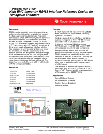
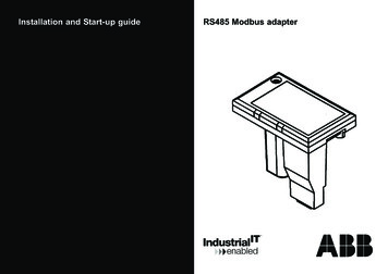
3.1 Communication modeMODBUS protocol uses half-duplex communications, regardless of the hardware.Half-duplex hardware shares the same lines for transmit and receive, whereas, full-duplex hardware has dedicated transmit and receive lines.3.2 SINGLE ENDED versus DIFFERENTIAL data transmission- Single-ended transmission is performed on one signal line, and thelogical state is interpreted with respect to ground. The main disadvantage of the single-ended solution is its poor noise immunity.Point to point – single endedMulti point – differential- For differential transmission, a pair of signal lines is necessaryfor each channel. On one line, a true signal is transmitted, whileon the second one, the inverted signal is transmitted. Thereceiver detects voltage difference between the inputs andswitches the output depending on which input line is more positive. Differential data transmission schemes are less susceptibleto common-mode noise than single-ended schemes.Point to point – differential5
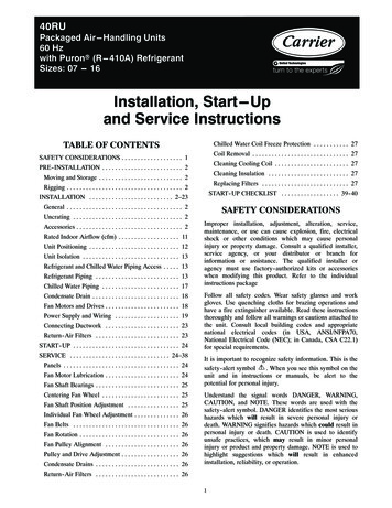
3.3 RS-232 interfaceAn RS-232 interface is rated for distances up to 15 meters (50 feet). At least three wires are required for an RS-232 interface. Wires are required forTransmit, Receive and Signal Ground. Some devices support additional wires for communication handshaking. RS-232 hardware is a full-duplex configuration, having separate Transmit and Receive lines.Each signal that transmits in an RS-232 data transmission system appears on the interface connector as a voltage with reference to a signal ground.The RS-232 receiver typically operates within the voltage range of 3 to 12 and -3 to -12 volts.3.4 RS-422 interfaceAn RS-422 interface requires at least four wires. Two wires each are used for Transmit and Receive. A fifth wire is usually required for Signal Ground,when connecting non-isolated devices together. Handshaking lines may also be supported by some hardware. This interface is full duplex, allowinguse of the same software drivers as for RS-232. The differential drivers allow for distances up to 1200 meters (4000 feet). The receivers of an RS422 device are always enabled.3.5 RS-485 interfaceFor multi-drop operation, drivers must be capable of tri-state operation.An RS-485 interface requires at least two wires. In a two-wire configuration, the same pair of wires is used for Transmit and Receive. The two-wireconfiguration utilizes half-duplex communications. Transmit driver circuits are always taken off-line or tri-stated, when not in use. This tri-state featurereduces the load on the network, allowing more devices, without the need of special hardware. This interface also uses differential drivers, supporting distances up to 1200 meters (4000 feet).In a differential system the voltage produced by the driver appears across a pair of signal lines that transmit only one signal. A differential line driverwill produce a voltage from 2 to 6 volts across its A and B output terminals and will have a signal ground (C) connection. Although proper connectionto the signal ground is important, it isn't used by a differential line receiver in determining the logic state of the data line.A differential line receiver senses the voltage state of the transmission line across two signal input lines, A and B. It will also have a signal ground (C)that is necessary in making the proper interface connection. If the differential input voltage Vab is greater than 200 mV the receiver will have a specific logic state on its output terminal. If the input voltage is reversed to less than -200 mV the receiver will create the opposite logic state on its output terminal.3.6 Bias resistorsRS-422 and RS-485 networks often require bias, or pull-up and pull-down resistors. These resistors are used to stabilize the network. By definition,in a MODBUS RTU network, it is the responsibility of the Master to provide this function.Some systems may function without these stabilizing resistors, but may be more susceptible to communication errors. Though the pull-up and pulldown resistors are the same, the value of these resistors varies from device to device. The actual recommended resistance may be calculated, andvaries with the number of devices on the bus.6
3.7 Termination resistorsTermination resistors are often used to reduce reflections on the network. This problem occurs most with long wires and high baud rates. Due to variations in wire and equipment, whether or not to use these terminators is usually determined by system testing. The general rule is to add them onlyif needed. The resistors are typically 120 ohms, and installed across the Transmit and Receive wire pairs. Normally, one resistor is installed at eachend of each pair of wires.3.8 Shielding and grounding considerationsThe signal ground conductor is often overlooked when ordering cable. An extra twisted pair must be specified to have enough conductor
RS-422 and RS-485 networks often require bias, or pull-up and pull-down resistors. These resistors are used to stabilize the network. By definition, in a MODBUS RTU