Transcription
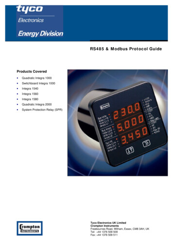
TI Designs: TIDA-01630High EMC Immunity RS485 Interface Reference Design forTamagawa EncodersDescriptionEMC immunity, especially immunity against inverterswitching noise, is important for positioning encoderfeedback systems of industrial drives. This designdemonstrates a high EMC immunity RS485 transceiversolution which can be used on both the drive andencoder, such as Tamagawa , EnDat 2.2, BiSS ,and so forth. The design supports a wide input voltageof 5 V. A connector with 3.3-V logic I/O signals and a3.3-V power supply allows direct interface with thehost processor to run the master protocol and powerthe processor. To meet the supply range of theselected encoder, the design offers an output voltageto the encoder equal to the Vin. This design’s powersupply offers protection against overvoltage and shortcircuit, according to the selected encoder’s voltagerange, to prevent damage during a cable short. Thedesign has been tested for up to a 50-m cable lengthwith the Tamagawa 2162TPS61240TPS22810Launchxl-f28379dDesign FolderProduct FolderProduct FolderProduct FolderProduct FolderProduct FolderTool FolderFeatures 5-V half-duplex RS485 transceiver with up to 50Mbps baud rate and improved EMC immunityagainst IEC61000-4-4 Hardware supports 2-wire interfaces standards,such as Tamagawa, or 4-wire RS485 interfacestandards, such as EnDat2.2 and BiSS 5-V supply half-duplex RS485 transceiverTHVD1550 with 16-kV IEC-ESD and 4-kV EFTeliminates cost for external ESD components. Highest immunity against IEC61000-4-4 fastelectrical transients versus other industry standardRS485 transceivers, validated in system tests Designed to meet IEC61800-3 EMC immunity forvariable-speed drives without the need foradditional protection devices, such as TVS diodes,when used in applications with encoders usingshielded cables The design is in BoosterPack plug-in moduleform factor, with a connector compatible to the TILaunchPad Development Kit for easy evaluationof Tamagawa with a C2000 MCUApplications Servo CNC and Robotics AC Inverter and VF Drives Position Sensor (Encoders) Industrial RobotsASK Our E2E ExpertsTIDA-01630Input:5 V -15 VDC r(Encoder Supply)Cable lengthup to 50 mDC/DC5V/1ALaunchPad Adapter(J5/J7 and J6/J8)Level Shifter3V3 to 5 VStatus LEDsTIDUE61 – March 2018Submit Documentation FeedbackSub-D15 28379DDC/DC3V3 / 1 AHigh EMC Immunity RS485 Interface Reference Design for TamagawaEncodersCopyright 2018, Texas Instruments Incorporated1
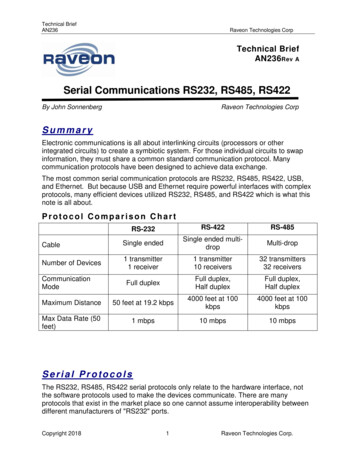
System Descriptionwww.ti.comAn IMPORTANT NOTICE at the end of this TI reference design addresses authorized use, intellectual property matters and otherimportant disclaimers and information.1System DescriptionAbsolute digital encoders acquire absolute position or rotary angle and feedback, typically in industrialdrives, such as servo drives, CNC, and robotics EE.Multiple protocol standards are based on RS485/RS422, with synchronous or asynchronouscommunication and a protocol-specific encoder supply voltage range. Drive customers are looking for auniversal RS485 digital interface to enable their drive to support the absolute encoder which best fits theirsystem.The trend is for more precise and robust control of motors, additional safety features, and predictivemaintenance for lesser or complete avoidance of shut-down time.Devices able to withstand harsh industrial environments yield higher reliability and less down-time In real drives, the most critical noise is the PWM switching noise, coupled into the shield of the powercable during the high-voltage PWM switching transients. These transients can be 10 kV/µs with IGBT,and up to 50-100 kV/µs with SiC in the future. These transients can couple typically as AC commonmode transients into the RS485 differential signals. EFT and INS common-mode noise are closest tothe real impulse noise in drives. Corrupt communication (bit errors), even when detected with a CRC error, make the current position orangle read data invalid, and can impact the performance of the drive. In a worst case scenario, thedrive must shut down due to lack of angle correct information.The EMEA/U.S. drive and encoder customers focus on RS485 immunity against ESD, surge, andEFT/INS. The trend to faster switching GaN and SiC with higher impulse noise than today’s IGBT furtherincreases the importance of an RS485 transceiver with high EMC (EFT) immunity.Figure 1 shows a simplified system block of a hardware interface module supporting digital absoluteposition encoders. The design is shown as a subsystem of an industrial servo drive connected to theabsolute position encoder; the RS485 transceiver is needed in both the encoder and the drive.3-Phase power cable to motor: High-voltage transients of up to 100 kV/usthat can couple into the encoder cable, especially as common modetransient noiseI-V FeedbackControlPowerApplicationCommunicationCable length up to100 m and moreEncoder Master ProtocolPosition Feedback ModulePoLEnoder P/SACMotorRS422/RS485 PHYPending protocolIncl. power over RS485RS485 communication (Digital angle)needs to be immune against EFT,surge, ESDServo Drive1-4 RS485 Transceivers pending protocol Standard andsingle or dual encoder interface1-2 RS485 Transceivers pendingprotocol StandardAbsolute Position Encoderw/ RS485Figure 1. Industrial Drive with Digital Interface to Absolute Position Encoders2High EMC Immunity RS485 Interface Reference Design for TamagawaEncodersCopyright 2018, Texas Instruments IncorporatedTIDUE61 – March 2018Submit Documentation Feedback
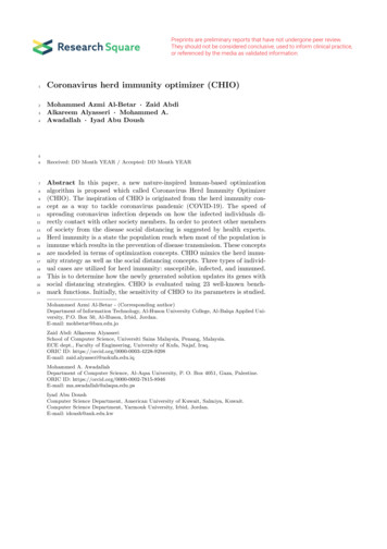
System Descriptionwww.ti.com1.1EC61800-3 EMC Immunity StandardWhen building an industrial drive, the customer must pass the compliance test of the IEC61800-3 EMCstandards.For more details on the IEC61800-3 standard, see the blog , or the video .The blog shows that there are several interfaces which must be tested.For this design, the signal interface is tested; this focus is on surge and EFT immunity.Table 1. IEC618000-3 EMC EFT Immunity Requirements for Second Environment, MeasuredVoltage Levels, and ClassRequirementsPortPhenomenonBasic StandardLevelPerformance(Acceptance) CriterionPorts for control linesand DC auxiliarysupplies 60 VFast transient Burst(EFT)IEC61000-4-4 2 kV / (5 kHz or 100kHz), capacitive clampBPorts for control linesand DC auxiliarysupplies 60 VSurge 1, 2/50 µs, 8/20µsIEC61000-4-5 1 kV. Because theshielded cable 20 m,direct coupling to shield(2 Ω / 500 A)BThe performance (acceptance) criterion is defined, as follows:Performance (Acceptance)CriterionDescriptionAThe module continues to operate as intended. No loss of function or performance, includingthe duration of the test.BTemporary degradation of performance is accepted. After the test, the module continues tooperate as intended, without manual intervention.CDuring the test, loss of functions accepted, but no destruction of hardware or software. Afterthe test, the module continues to operate as intended automatically, after manual restart, orpower off, or power on.Depending on the geographic location where the drive is EMC tested, there are other IEC standards forelectrical fast transients.For example, Japan specifies an additional standard: the NECA TR-28 for impulse noise (INS). Thisdesign was tested against IEC61000-4-4.1.2TI Design OverviewThis TI design implements a high EMC immunity RS485 digital interface for absolute position encoders,using Tamagawa T-Format.The major building blocks of this TI hardware design are the bidirectional 2-wire RS485 interface, theencoder power supply protected by a load switch, and a 3.3-V digital interface to a host processor to runthe corresponding encoder standard protocol. The host processor that runs the corresponding encodermaster protocol is not part of this design.The absolute position encoder can be connected to the reference design, either through a SubD-15connector or a 10-pin header. The connector has dedicated pins needed for the data lines and theencoder power supply. This design supports cable lengths of up to at least 50 m. For cable specifications,refer to the recommendations of the corresponding encoder vendor.A block diagram is shown in Figure 2.TIDUE61 – March 2018Submit Documentation FeedbackHigh EMC Immunity RS485 Interface Reference Design for TamagawaEncodersCopyright 2018, Texas Instruments Incorporated3
System Descriptionwww.ti.comThe design has been tested for EMC immunity against fast transient burst (EFT), with levels specified perIEC61800-3 and above standard. For details on the EFT, see the section below. There are multipleabsolute position encoder protocol standards that use RS-485 or RS-422-based serial digital interfaces,such as EnDat 2.2, BiSS, or HIPERFACE DSL. Further interface standards include PROFIBUS DP andPROFIBUS IO, as well as CAN or Ethernet-based interfaces. Additional standards include proprietary,drive vendor-specific standards, such as Tamagawa, Fanuc Serial Interface, Mitsubishi High-SpeedSerial Interface, and this TI design supports the Tamagawa T-format serial interface.For more details on the different standards, see the following TI designs listed in Table 2, listed perprotocol.Table 2. Absolute Position Encoder Digital Interface TI Designs1.3Encoder ProtocolTI DesignEndat2.2TIDA-00172, TIDA-00179, TIDA-01401, TIDM-1008BiSSTIDA-00175, TIDA-00179, TIDA-01401HiperfaceDSLTIDA-00177, TIDA-00179HiperfaceTIDA-00202TamagawaTIDA-01630, TIDA-00179Key System SpecificationsTable 3. TIDA-01630 Specifications4ParameterValueCommentDC input voltage5V2.1-mm ID / 5.5-mm ODM barrel DC jack.5-V input to supply the board.RS485 interface1 channel half duplex 5-V RS485transceiverCan be configured for use in both encoderand drive interface.Encoder power supplyDC input voltageSame as DC input voltage, can be turnedcontrolled using a load switch using I/OinterfaceI/O interface signaling voltage3.3 VBoosterPack for launchxl-f28379d, for pinassignment; see Table 8RS485 transceiver power supply3.3 V or 5 VFlexible power supply for 3.3-V or 5-Vversions of RS485 transceivers. Default 5V.RS485 transfer rate50 MBaudSupports all standard encoder protocols.50 MBaud improves rate reach.Temperature range-40 to 85 CIndustrial temperature range -40 to 85 C.No heat sink required.Electromagnetic compatibility (EMC)According to IEC61800-3Designed to exceed IEC61800-3 EMClevels and pass criterion for ESD, EFTand surge according to test methoddescribed in: IEC61000-4-4 IEC61000-4-5Encoder connectorSub D-15 or 10-pin headerSee section Section 3.1.1.4 for pinoutEncoder standardTamagawaPending SW for C2000. For furtherdetails, refer to the forum e2e.ti.comIndicator LEDsPower rails, 3 I/O controlled3.3 V, 5 V, and Encoder PS andLaunchPad LEDs for test and debugoptionHigh EMC Immunity RS485 Interface Reference Design for TamagawaEncodersCopyright 2018, Texas Instruments IncorporatedTIDUE61 – March 2018Submit Documentation Feedback
System Overviewwww.ti.com2System Overview2.1Block DiagramTIDA-01630Input:5 V -15 VReversepolarityprotectDC jackLoadSwitchTamagawaEncoder(Encoder Supply)Cable lengthup to 50 mDC/DC5V/1ALaunchPad Adapter(J5/J7 and J6/J8)Level Shifter3V3 to 5 VStatus LEDsSub-D15 28379DDC/DC3V3 / 1 AFigure 2. System Block Diagram of TIDA-016302.2Design ConsiderationsThis design has three major hardware blocks: the digital interface, the power supply for the digitalinterface, and the power supply for the encoder.These three blocks are explained in the hardware design section.A brief overview of the software required to use the TI Design is also given.2.2.1Hardware Design2.2.1.1Digital InterfaceRS-485 Transceiver CircuitsThe Tamagawa T-format protocol is an asynchronous communication which runs up to a maximum of 2.5MHz frequency on the data communication path.Parameters with regards to RS-485 transceivers taken into consideration are listed in Table 4.Table 4. RS-485 Parameters From Corresponding Datasheets (SLLSEV1)PARAMETERTHVD1550Supply voltage (recommended)5VBaud rate (maximum)50 MbpsReceiver propagation delay (maximum)40 nsDriver propagation delay (maximum)16 nsReceiver rise/fall time (maximum)6 nsDriver rise/fall time (maximum)6 nsSupply current (quiescent) driver and receiver enabled700 µAIEC61000-4-4 EFT (absolute maximum ratings) 4 kVTIDUE61 – March 2018Submit Documentation FeedbackHigh EMC Immunity RS485 Interface Reference Design for TamagawaEncodersCopyright 2018, Texas Instruments Incorporated5
System Overviewwww.ti.comWith that information, the RS-485 device chosen for the design is the THVD1550.RS-485 Termination and Transient ProtectionInstead of single 220-Ω / 0.1-W resistors, two smaller resistors 0603 in series 0.1 W each have beenchosen. A pulse-proof resistor is added to the A and B bus lines if a transient voltage is higher than thespecified maximum voltage of the transceiver bus terminals. These resistors limit the residual clampingcurrent into the transceiver, and prevent it from latching up. In data receive mode, due to the low inputcurrent of typical 240 μA, the voltage drop across the 10-Ω resistors is negligible. In the clock and datatransmit direction, the voltage drop across both 10-Ω resistors is around 15%, which results in a slightlylower transmit differential voltage.To further improve immunity against common-mode noise, two different circuits choice are shown.Option 1: 220-pF bypass capacitors are added from each of the differential RS-485 outputs A and B, toGND. See C19 and C22 in Figure 9; these capacitors must be high quality capacitors (NP0/C0G).Option 2: A 470-pF bypass capacitor is added at the center point of the termination resistors R42 andR43. This bypass capacitor removes the need to match the capacitors to have the same effect on thecommon mode during an event. The difference in the resistor values affects the equal distribution o
EFT/INS. The trend to faster switching GaN and SiC with higher impulse noise than today’s IGBT further increases the importance of an RS485 transceiver with high EMC (EFT) immunity. Figure 1 shows a simplified system block of a hardware interface module supporting digital absolute position encoders. The design is shown as a subsystem of an industrial servo drive connected to the absolute .