Transcription
Checklist for Setting up QuickPanel View MODBUS Connection to aMODBUS Capable GE Fanuc Device with Native Drivers
Introduction:This document is a brief introduction to the configuration of the QuickPanel View toan MODBUS Capable GE Fanuc device (IC693CPU352) with Native Drivers. Thisdocument assumes that you have already started a project with a QuickPanel Viewcomponent added and have basic knowledge of downloading to a target.For setup, you will need:1 - copy Proficy Machine Edition (PLC Standard & View Standard)1 - Series 90-30 Rack1 – Series 90-30 Power Supply (IC693PWR*)1 – Series 90-30 CPU (IC693CPU352 or any other listed hardware on the enclosed list)1 – Programming Cable IC690ACC9011 – communication cable from PLC component to QuickPanel View. Reference cablelist at the back of the manual for connection media needed.1 – QuickPanel View Intermediate, Loaded or Fully Loaded (IC754VxI*, IC754VxL* orIC754VxF*) with a 24VDC power supplyReferences:Proficy Machine Edition online helpGFK-2075GE Fanuc Knowledge Base (support.ge.com)
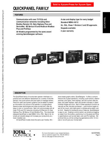
GE Fanuc MODBUS Capable Devices
Configuring the QuickPanelRight click the “View Native Drivers” then navigate to the MODBUS driver and leftclick.Right click on the MODBUS driver and choose “Properties”.The “Inspector” window will show the driver properties. Left click the ellipse.Choose the desired “Baud Rate” & “Parity”. Please note that these settings mustmatch the “Data Rate”& “Parity” settings configured for the PLC in the “Port 1 RS 232”tab of the hardware configuration tool. Click on “OK”.
We now must add a device. Devices represent the actual hardware that your ViewDeveloper application communicates with.Right click the “Device 1”Left click the ellipseto launch the “MODBUS Address Device Wizard” tool.You must specify a “device address” that is the address specified for the PLChardware in the ““Station Address” found under the “Port 1 RS 232” tab of thehardware configuration tool. Click on “OK”.At this point you would build your application and variables that you want tocommunicate and download to the QuickPanel View.
Configuring a PLC for MODBUS RTU SlaveRight click the project name, choose “Add Target” and mouse over to “Series 90-30PLC”.Choose some hardware that is capable of the MODBUS RTU Slave as laid out in thebeginning of this guide.
As mentioned previously, in our example we choose the Series 90-30 IC693CPU352.You will be prompted with the following. Choose “Yes”.You will be prompted with the following. Choose “Yes”.The “Infoviewer” will automatically pop up the properties for the added CPU.
From the provided table, either port 1 or 2 will do MODBUS RTU Slave. We will chooseport 1 so that we can stay online as with the programmer. Choose the “Port 1 (RS232)” tab.Double left click on the “Port Mode”Choose “RTU Only” and left click on “OK”.Choose the desired “Data Rate” & “Parity. Please note that these settings must matchthe “Baud” & “Parity” settings configured for the QuickPanel View in the “configureMODBUS Driver” dialog. In addition you must specify a “Station Address” that isunique.Go online and download the changes to your CPU.
Addressing to the MODBUS Capable GE Fanuc HardwareSince the QuickPanel View will be using Modicon addressing scheme, this can causeconfusion when a user tries to interface a GE Fanuc PLC.Modicon uses either four digit addresses or five digit addresses, depending on thePLC model. The key is the most significant digit of the reference address. Thefollowing table lists each reference type, the most significant digit and the GE Fanucreference type.0---Outputs %Q1---Inputs %I3---Analog Inputs %AI4---Registers %RFor example, if you want to read %R1 in a GE Fanuc PLC, the four digit address wouldbe 4001 and the five digit address would be 40001. The MMI/DCS will format theaddress into the proper form for an RTU query and the GE Fanuc RTU slave device willinterpret the address in the RTU query as a GE Fanuc address.
Connection MediaSpecified GE Fanuc Hardware (as stated in the table in this manual)15 pin SNP Programming PortIC693CMM311 & IC697CMM711Port 1Port 2
IC693CPU351/352/363 RJ11 PortVersaMax Nano/Micro RJ45 PortVersaMax IC200CPU001/002/005 9 PinTyler HolmSenior Support ProfessionalGE Fanuc Intelligent PlatformsT 1 780 420 2168E tyler.holm@ge.com
list at the back of the manual for connection media needed. 1 – QuickPanel View Intermediate, Loaded or Fully Loaded (IC754VxI*, IC754VxL* or IC754VxF*) with a 24VDC power supply References: Proficy Machine Edition online help GFK-2075 GE