Transcription
CORNERSTONE DocumentationRelease 2.5Luceda PhotonicsOct 27, 2021Contents1Changelog22Introduction2.1 Process Design Kit (PDK) based design concept . . . . . . . . . . . . . . . . . . . . . . . . . . . . .553Getting Started3.1 Extracting the PDK . . . . . . . . . . . . . . . . . . . . . . . . . . . . . . . . . . . . . . . . . . . .3.2 Using the PDK with IPKISS Link for Siemens EDA . . . . . . . . . . . . . . . . . . . . . . . . . . .3.3 Using the PDK with IPKISS . . . . . . . . . . . . . . . . . . . . . . . . . . . . . . . . . . . . . . .88884Technology settings4.1 Selecting the target technology . . . . . . . . . . . . . . . . . . . . . . . . . . . . . . . . . . . . . .4.2 Layers . . . . . . . . . . . . . . . . . . . . . . . . . . . . . . . . . . . . . . . . . . . . . . . . . . .1010105Components5.1 Which components are available to use from the IPKISS PDK for CORNERSTONE?5.2 How to use IPKISS PDK for CORNERSTONE components? . . . . . . . . . . . . .5.3 Luceda picazzo components . . . . . . . . . . . . . . . . . . . . . . . . . . . . . .5.4 How to customize a component design? . . . . . . . . . . . . . . . . . . . . . . . .1212121213Component List6.1 Grating Couplers . . . . . .6.2 Multi Mode Interferometers6.3 Crossings . . . . . . . . . .6.4 Ring Filters . . . . . . . . .6.5 Modulators . . . . . . . . .6.6 Heaters . . . . . . . . . . .6.7 Y-Splitters . . . . . . . . . .14142235394549556.
This document explains how to use the IPKISS Process Design Kit (PDK) for CORNERSTONE (version 2.5).The PDK can be used from IPKISS, providing the following functionality: definition and layout of circuits using CORNERSTONE’s predefined library of cells (building blocks), which isentirely available within IPKISS, waveguide routing using the waveguide types defined by CORNERSTONE, or custom defined waveguidesfollowing CORNERSTONE design rules, definition of custom devices using CORNERSTONE layers and design rules, simulation of custom devices using IPKISS’ built-in solvers and interfaces to 3rd party tools such as DassaultSystems CST Studio Suite and Lumerical FDTD Solutions, circuit editing from Siemens L-Edit using IPKISS Link for Siemens EDA.This document explains how to get started with the PDK, lists the cells that are available and documents the technologyfor custom design.1 ChangelogThis changelog shows the changes in the IPKISS PDK for CORNERSTONE.2.5 Updated for IPKISS 3.72.4 Updated SOI220nm 1550nm TE STRIP 2X1 MMI, SOI220nm 1550nm TE RIB 2X1 MMI Updated SOI340nm 1310nm TE STRIP 2X2 MMI, SOI340nm 1310nm TE RIB 2X2 MMI2.3 Added:SOI220nm 1550nm TE RIB Grating Coupler, SOI220nm 1550nm TE STRIP 2X1 MMI,SOI220nm 1550nm TE STRIP 2x2 MMI,SOI220nm 1550nm TE STRIP 2x1 Ysplitter,SOI220nm 1550nm TE STRIP Grating Coupler,SOI220nm 1550nm TM STRIP Grating Coupler,SOI220nm 1310nm TE RIB Grating Coupler,SOI220nm 1310nm TE STRIP 2X1 MMI,SOI220nm 1310nm TE STRIP 2x2 MMI,SOI220nm 1310nm TE STRIP 2x1 Ysplitter,SOI220nm 1310nm TE STRIP Grating Coupler,SOI220nm 1310nm TM STRIP Grating Coupler,SOI340nm 1550nm TE STRIP Grating Coupler,SOI340nm 1310nm TE STRIP Grating Coupler,SOI340nm 1550nm TE RIB STRIP Apodised Grating Coupler, SOI340nm 1550nm TE RIB RIB Apodised Grating CoupSOI500nm 1550nm TE RIB 2X2 MMI,SOI500nm 1550nm TE RIB Grating CouplerandSOI500nm 1550nm TM RIB Grating Coupler UpdatedSOI220nm 1550nm TE RIB 2X1 MMI,SOI220nm 1310nm TE RIB 2X1 MMI,SOI220nm 1310nm TE RIB 2x2 MMI,SOI220nm 1310nm TE RIB GC,SOI340nm 1310nm TE RIB GC,SOI340nm 1310nm TE STRIP GCandSOI500nm 1550nm TE RIB 2X1 MMI Updated SOI 500nm vfab RenamedSOI340nm 1550nm TE RIB STRIP Apodised Grating CouplerSOI340nm 1550nm TE RIB STRIP Apodised Grating Couplerto
2.2.luceda1 Updated this PDK to be compatible with IPKISS 3.4 Renamed OA folder to openaccess2.2Important: Only update of 340nm (later 220 and 500) Updated 340nm components Added 340nm components Added Ebeam and Blocking layers2.1 global: add RIB AllPass Ring, RIB AddDrop Ring, STRIP AllPass Ring and STRIP AddDrop Ring rename SOI220nm 1550nm TE RIB Grating Coupler RIBTapered to . . . . Coupler RibTapered2.0Important: No backward compatibilty!Updates in view of CORNERSTONE MPW call 11 global: renamed all the components to make their application case (wavelength and polarization) more clear global: 1x2 MMI replaced by 2x1 MMI global: remove parametric crossings 220nm SOI: change the MZIs (1.5um modulator length instead of 1.8um) 220nm SOI: fix the predefined crossings 340nm SOI: change the components from Strip to Rib1.3.0Updates in view of CORNERSTONE MPW call 10 global: change the way to select the technology (see Section 4) global: add label layer (GDS 100) global: add parametric crossings and rib modulator 220nm SOI technology: update some dimensions 200nm SOI devices added: fixed crossings and Mach-Zehnder modulators1.2.0Updates in view of CORNERSTONE MPW call 9 500nm SOI technology variant added example scripts 500nm SOI devices added: grating coupler and MMI PHC layer added for photonic crystal devices1.1.0 Updates in view of CORNERSTONE MPW call 71.0.1 Fix: the predefined grating couplers now have 60 grating periods.
1.0.0Initial IPKISS PDK for CORNERSTONE release: Technology settings, drawing layers, GDSII, IPKISS Link for Siemens EDA compatibility, waveguides, MMIand grating coupler building blocks, virtual fabrication for passives. The technology settings (virtual fabrication) has both 220nm and 340nm SOI flavours. The device library is220nm SOI only at this point.
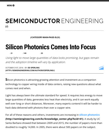
2 Introduction2.1 Process Design Kit (PDK) based design conceptIf you already know about Process Design Kits (PDKs) in general, please skip to the section Getting started.A PDK helps to bridge the gap between the fab or foundry offering IC technology and the designer who creates an ICdesign in that technology, as shown by Figure 2.1. In order to create a design, the designer needs to have the librarycells created by the fab available, as well as technology details required for custom design of components. A PDK isimplemented for a specific set of software tools.Fig. 2.1: Concept of a Process Design Kit (PDK)Luceda develops such a PDK so that it can be used by the IPKISS tools (IPKISS Link for Siemens EDA or IPKISS).To this end, in general, an IPKISS PDK has several components: Technology settings that allow for custom design:– Layers for drawing on, in accordance with the foundry’s definitions.– Design rules, which provide dimensional constraints for the design to be manufacturable.– A design rule checking (DRC) deck, checking that the designer’s mask layout adheres to the foundry’sdesign rules.– A technology description that allows to generate 2D and 3D models that can be sent to physical simulationtools such as for FDTD or mode propagation.– Routing settings for optical waveguides and electrical wiring The fab’s cell library, providing validated building blocks to the designer:– Layout models that allow to place and connect the cells in the layout. These can be ‘black-box’: thedetailed layout may not be visible, only the optical and electrical I/O and the bounding box.– Simulation models that allow for simulation and functional verification of a circuit based on these cells. Parametric cells for typical complex cells or repetitive tasks that a designer would like to do Examples and (this) manual to get started
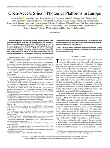
The combination between Luceda’s design software and the IPKISS PDK for CORNERSTONE is what enables thedesigner to create a design specific for the CORNERSTONE technology.Note: In this text, the words cell, component and building block are used interchangeably. In the context of a PDK,a cell, building block or component usually delivers a specific unit function, such as a fiber coupler, splitter or phasemodulator. There could also be more complex cells in the PDK library though. In the context of the user design, cellcould mean any design or hierarchical part thereof.Use case: PDK cell library based designThe IPKISS PDK for CORNERSTONE provides a library with a number of predefined cells for the C band (1550nm)and O band (1310nm). With this library available from IPKISS, the designer can create a circuit directly in code(IPKISS) or from the L-Edit GUI using drag-and-drop of devices from the library (IPKISS Link for Siemens EDA).After placing the PDK cells, optical waveguides can be drawn in a manual or semi-automated fashion. In addition, thePDK provides the necessary settings to use picazzo, Luceda’s pcell template library with functions like ring resonators,MMIs, modulators, Mach-Zehnder interferometers, fanouts, and many more.This approach allows for fast prototyping of designs using the CORNERSTONE technology.Use case: Custom cell designIn a lot of cases, the user will want to design custom components and include them in the design. IPKISS providesseveral functions for that purpose: Parametric cells can be defined fully in Python script, with their parameters (properties in IPKISS), layout andsimulation model. Basic building blocks can be virtually fabricated and sent to electromagnetic simulation tools such as FDTDand EME. IPKISS has a built-in mode solver CAMFR and provides interfaces to CST Studio suite and other 3rdparty tools. More complex subcircuits defined in IPKISS can be simulated using the built-in compact model solver Caphe.The designer can provide models for the basic building blocks, or generate them from simulation or measurement data. The designer can maintain the resulting parametric cells in a library and use them from the IPKISS Link forSiemens EDA environment or in an IPKISS python code design.Use case: Using internal and 3rd party librariesIn a larger design team or in the case of consecutive design projects, a designer or a design team will typically buildup their own library of subcircuits that perform specific reusable functions. Using Luceda’s software, the designeror design team can create such proprietary libraries that work together with the IPKISS PDK for CORNERSTONE.These re-usable libraries can then be shared within the team, outside of the company or used in consecutive projects.The designer can in this way embed and sustain design knowledge in a library, and base a new design both on the PDKas well as these internal libraries.One step further, a designer can also acquire 3rd party libraries and use them in a design project in the same way.
Fig. 2.2: Designing with reuseable design libraries and a PDK.
3 Getting StartedThis section explains how to load the PDK in IPKISS and basics of how to use it.If you are unfamiliar with IPKISS, please have a look at the IPKISS documentation and samples. The documentationand samples are available from the IPKISS Control Center.The latest IPKISS documentation is also available online at http://docs.lucedaphotonics.com/index.html.3.1 Extracting the PDKThe PDK is distributed as a zip file, which you can extract with the unzip utility of your choice (unzip, WinZip, 7-zip,. . . ).For the purpose of this manual, we assume you have unzipped “cornerstone-2.5.zip” as C:\temp\cornerstone.You can inspect the directory structure of the PDK: data/: Contains GDS files of some fixed cells docs/: Contains this file docs/examples/scripts: Example IPKISS python scripts docs/examples/lib.defs: Example of IPKISS Link for Siemens EDA design project ipkiss/: IPKISS technology, pcells, models and functions (Python) openaccess/: Design libraries openaccess/cornerstone/: OpenAccess database for the PDK (L-Edit) techfiles/: Tech files (layers, display) for various tools techfiles/klayout/: Layer settings for KLayout GDSII visualization3.2 Using the PDK with IPKISS Link for Siemens EDAYou can follow the instructions given in our documentation torialpdk based circuit/index.html.3.3 Using the PDK with IPKISSSetting up the editor environmentYou can follow the instructions given in our documentation nvironment setup/create project pdk.html.ExamplesThe PDK comes bundled with a series of examples for use in IPKISS, in theC:\temp\cornerstone\docs\examples\scripts folder. These are executable Python files. The examples are agood starting point to learn how to design with the IPKISS PDK for CORNERSTONE. Below is a summary of theshipped examples:
Example nameexample layers.pyexample waveguides.pyexample heater.pyexample design passive.pyexample modulator vfab.pyexample customcell.pyexample phc soi220.pyexample components 220.pyexample phc soi340.pyexample components 340.pyexample phc soi500.pyexample components 500.pyDescriptionVisualize all the layers that are available in the cornerstone technologyVisualize the waveguides available in the cornerstone technologyExample of a waveguide with a heater filamentExample of a parameter sweep of ring resonators with automated fiber coupler embeddingExample of a cross section visualization for one of the fixed MZMCreate a custom PCell in IPKISS using the CORNERSTONE technologyExample of a photonic crystal component using the Luceda picazzo3 libraryfor 220nm platformShows the PDK components for 220nm platformExample of a photonic crystal component using the Luceda picazzo3 libraryfor 340nm platformShows the PDK components for 340nm platformExample of a photonic crystal component using the Luceda picazzo3 libraryfor 500nm platformShows the PDK components for 500nm platformReferences IPKISS documentation: http://docs.lucedaphotonics.com/latest/index.html Library atest/ipkisseda/libraries/library organization/index.
4 Technology settingsThe PDK contains layer definitions and virtual fabrication settings for the 220nm, 340nm and 500nm SOI processes.Refer to the CORNERSTONE design rule manual and MPW call documents for detailed information.4.1 Selecting the target technologyOne PDK is used to target all the technologies. At the start of an Ipkiss script, you can import the library correspondingto the technology variant you need.For example, the 220nm SOI process:import cornerstone soi220.all as cornerstoneThis sets the virtual fabrication process of the 220nm SOI process and imports only the process specific componentsand the generic pcells.Process220nm SOI340nm SOI500nm SOITable 4.1: List of processesLibrarySpecific cells prefixcornerstone soi220 SOI220nmcornerstone soi340 SOI340nmcornerstone soi500 SOI500nm4.2 LayersThe following table gives an overview of the available layers and how they are named in Ipkiss. See the CORNERSTONE design rules manual for further information about the layers defined by CORNERSTONE.
Table 4.2: Layer TableLayer nameWGWG BLEEDLBLDescriptionSilicon Etch - Waveguides (Light field)Silicon Etch - Waveguides (Dark field)Silicon Etch - GratingsSilicon Etch - Rib ProtectLow Dose p-type ImplantLow Dose n-type ImplantHigh Dose p-type ImplantHigh Dose n-type ImplantVias - rounded features cornersElectrodes - min gap between features 2µmHeater FilamentsHeater Contact PadsSilicon Etch - Photonic CrystalsE-beam etch layerProtection layer for waveguide etchCell OutlineBleed AreaLabel - DRC purpose layer then included inGDS 4STRIP TRACE Strip waveguide routing - Luceda non-tapeoutlayerRIB TRACERib waveguide routing - Luceda non-tapeoutlayerIPKISS LayerGDSNumberTECH.PPLAYER.WG3/0TECH.PPLAYER.WG LAYER.BLOCK61/0TECH.PPLAYER.NONE.CELL 99/0TECH.PPLAYER.NONE.BLEED 98/0TECH.PPLAYER.NONE.LBL100/0TECH.PPLAYER.STRIP TRACETECH.PPLAYER.RIB TRACE
5 Components5.1 Which components are available to use from the IPKISS PDK for CORNERSTONE?The IPKISS PDK for CORNERSTONE contains a number of predefined components that have been tested by the fab,as well as predefined waveguide templates. In addition, Luceda has provided a number of parametric cells to makelife of a designer easier.Users can use these components and mix them with their own custom designed components to create larger circuits.5.2 How to use IPKISS PDK for CORNERSTONE components?An example of how to instantiate (or place) PDK components in IPKISS, you may refer the sample located at: path to installed PDK \cornerstone\docs\examples\scripts\example components.pyFor 340nm SOI, refer to the example at path to installed PDK \cornerstone\examples\scripts\example components soi340.pyWith IPKISS, you may execute the sample Python code. In order to learn how to execute an IPKISS code, please referto section IPKISS.If you use IPKISS Link for Siemens EDA, you will be able to use your mouse to drag-and-drop the components inL-Edit. The explanation can be found in section IPKISS Link for Siemens EDA.Waveguide template componentsWaveguide trace template are used to define how the connecting waveguides between the devices should be like. Itcontains the technology information on the layers and geometrical drawing of a specific type of waveguide, such aswire or rib waveguides.Using the waveguide trace template, when users define the waveguide type at a device port and the connection linewith another device, the waveguide will be generated with the corresponding waveguide type at the port it connectsto. There are also devices that are drawn using the waveguide template as a layout parameter. It is useful in this caseto change the device design by updating the waveguide template.Two waveguide templates are predefined in the PDK: StripWaveguideTemplate, for strip waveguides fully etched tothe BOX, and RibWaveguideTemplate for rib waveguides with a thin SOI slab remaining. Both have a default width of400nm for O band and 450nm for C band.These templates have no models yet.5.3 Luceda picazzo componentsBesides the component library provided by the foundry, users are also able to use the component templates fromIPKISS’ Picazzo library.Note: Unlike the IPKISS PDK for CORNERSTONE components of which device performance is characterized andguaranteed by the fab, the Picazzo library components are up to the user to ensure compatibility with the design rulesand the designed device manufacturability and performance.The list of Picazzo library components and their documentation can be found in the IPKISS manual: http://docs.lucedaphotonics.com/latest/picazzo/In the documentation examples, we use the silicon photonics as the technology library (a demo technology libraryfrom IPKISS). Now that we have a real-world PDK, we are able to use it as the technology library for the picazzodesign.
Photonic crystalsPicazzo offers a lot of components for drawing photonic crystals: /index.html These however need some customization in order to work with CORNERSTONE: the SOI slab area needsto be explicitly added.For 220nm SOI, an example is in path to installed PDK \docs\examples\scripts\example phc soi220.py.For 340nm SOI, an example is in path to installed PDK \docs\examples\scripts\example phc soi340.pyFor 500nm SOI, an example is in path to installed PDK \docs\examples\scripts\example phc soi500.py5.4 How to customize a component design?Users can also choose start a component design from scratch, instead of starting from a CORNERSTONE librarycomponent or picazzo library component.An example is given in path to installed PDK \docs\examples\scripts\example customcell.py.
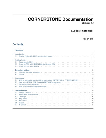
6 Component ListThese components have no models yet.6.1 Grating CouplersRIB Grating CouplerPCell for Grating Coupler in rib waveguide15105invertical inout051015403020100102030PortsNameinoutvertical 0,0.0)(0.0,0.0)Angle180.00.0180.0Waveguide clination0.00.090.0LayoutParameterssocket width: float and number 0 Width of the grating socket [um]line length: float and number 0 length of the grating trenches (perpendicular to the socket waveguide)line width: float and number 0 width of the grating trenches, drawn in the given layern o periods: int and number 0 number of periods of the gratingorigin: Coord2 local origin of the grating (first trench)period: float and number 0 period of the gratingsocket length: float and number 0 length of the straight waveguide socket
STRIP Grating CouplerPCell for Grating Coupler in strip waveguide15105invertical inout051015403020100102030PortsNameinoutvertical 0,0.0)(0.0,0.0)Angle180.00.0180.0Waveguide teLayoutParameterssocket width: float and number 0 line length: float and number 0length of the grating trenches (perpendicular to the socket waveguide)line width: float and number 0 width of the grating trenches, drawn in the given layern o periods: int and number 0 number of periods of the gratingorigin: Coord2 local origin of the grating (first trench)period: float and number 0 period of the gratingsocket length: float and number 0 length of the straight waveguide socketInclination0.00.090.0
220 nm SOI cellsSOI220nm 1550nm TE RIB Grating CouplerTE C-band rib grating coupler.806040in20vertical inout0201000100200300400PortsNameoutinvertical .0,0.0)(0.0,0.0)Angle0.0180.0180.0Waveguide clination0.00.090.0Waveguide teInclination0.00.090.0Waveguide teInclination0.00.090.0SOI220nm 1550nm TE STRIP Grating CouplerTE C-band strip grating coupler.PortsNameoutinvertical .0,0.0)(0.0,0.0)Angle0.0180.0180.0SOI220nm 1550nm TM STRIP Grating CouplerTM C-band strip grating coupler.PortsNameoutinvertical .0,0.0)(0.0,0.0)Angle0.0180.0180.0
SOI220nm 1310nm TE RIB Grating CouplerTE O-band rib grating coupler.PortsNameoutinvertical .0,0.0)(0.0,0.0)Angle0.0180.0180.0Waveguide clination0.00.090.0Waveguide teInclination0.00.090.0Waveguide teInclination0.00.090.0SOI220nm 1310nm TE STRIP Grating CouplerTE O-band strip grating coupler.PortsNameoutinvertical .0,0.0)(0.0,0.0)Angle0.0180.0180.0SOI220nm 1310nm TM STRIP Grating CouplerTM O-band strip grating coupler.PortsNameoutinvertical .0,0.0)(0.0,0.0)Angle0.0180.0180.0
SOI340nm 1550nm TE RIB Grating CouplerTE C-band rib grating coupler.806040in20vertical inout0201000100200300400PortsNameoutinvertical .0,0.0)(0.0,0.0)Angle0.0180.0180.0Waveguide clination0.00.090.0Angle0.0180.0180.0Waveguide clination0.00.090.0Waveguide teInclination0.00.090.0SOI340nm 1550nm TM RIB Grating CouplerTM C-band rib grating coupler.PortsNameoutinvertical .0,0.0)(0.0,0.0)SOI340nm 1550nm TE STRIP Grating CouplerTE C-band strip grating coupler.PortsNameoutinvertical .0,0.0)(0.0,0.0)Angle0.0180.0180.0
SOI340nm 1310nm TE RIB Grating CouplerTE O-band rib grating coupler.PortsNameoutinvertical .0,0.0)(0.0,0.0)Angle0.0180.0180.0Waveguide clination0.00.090.0Angle0.0180.0180.0Waveguide clination0.00.090.0Waveguide teInclination0.00.090.0SOI340nm 1310nm TM RIB Grating CouplerTM O-band rib grating coupler.PortsNameoutinvertical .0,0.0)(0.0,0.0)SOI340nm 1310nm TE STRIP Grating CouplerTE O-band strip grating coupler.PortsNameoutinvertical .0,0.0)(0.0,0.0)Angle0.0180.0180.0
SOI340nm 1550nm TE STRIP Apodised Grating CouplerTE C-band apodised strip grating coupler using e-beam.80604020vertical inout0200100200300400PortsNameoutvertical Angle0.00.0Waveguide eguide 0nm 1550nm TE RIB Apodised Grating CouplerTE C-band apodised rib grating coupler using e-beam.PortsNameoutvertical Angle0.00.0
SOI500nm 1550nm TE RIB Grating CouplerTE C-band rib grating coupler.806040in20vertical inout0201000100200300400PortsNameoutinvertical .0,0.0)(0.0,0.0)Angle0.0180.0180.0Waveguide clination0.00.090.0Angle0.0180.0180.0Waveguide clination0.00.090.0SOI500nm 1550nm TM RIB Grating CouplerTM C-band rib grating coupler.PortsNameoutinvertical .0,0.0)(0.0,0.0)
6.2 Multi Mode InterferometersParametric cellsRIB 2x1 MMIPCell for 2x1 MMI in rib .0Waveguide tersport width: float and number 0 Width of port [um]taper width: float and number 0 Width of taper [um]trace spacing: float and Real, number and number 0 Offset between the traces at the input and the outputmmi width: float and number 0 Width of the MMI [um]length: float and number 0 Length of the MMItransition length: ( float and Real, number and number 0 ), None allowed Length of the transition. Set toNone to take the standard transition length.
RIB 2x2 MMIPCell for 2x2 MMI in rib 5.0,1.0)Angle180.0180.00.00.0Waveguide .00.00.00.0LayoutParametersport width: float and number 0 Width of port [um]taper width: float and number 0 Width of taper [um]trace spacing: float and Real, number and number 0 Offset between the traces at the input and the outputmmi width: float and number 0 Width of the MMI [um]length: float and number 0 Length of the MMItransition length: ( float and Real, number and number 0 ), None allowed Length of the transition. Set toNone to take the standard transition length.
STRIP 2x1 MMIPCell for 2x1 MMI in strip 180.00.0Waveguide Parametersport width: float and number 0 Width of port [um]taper width: float and number 0 Width of taper [um]trace spacing: float and Real, number and number 0 Offset between the traces at the input and the outputmmi width: float and number 0 Width of the MMI [um]length: float and number 0 Length of the MMItransition length: ( float and Real, number and number 0 ), None allowed Length of the transition. Set toNone to take the standard transition length.
STRIP 2x2 MMIPCell for 2x2 MMI in strip .0,-1.0)(35.0,1.0)Angle180.0180.00.00.0Waveguide ination0.00.00.00.0LayoutParametersport width: float and number 0 Width of port [um]taper width: float and number 0 Width of taper [um]trace spacing: float and Real, number and number 0 Offset between the traces at the input and the outputmmi width: float and number 0 Width of the MMI [um]length: float and number 0 Length of the MMItransition length: ( float and Real, number and number 0 ), None allowed Length of the transition. Set toNone to take the standard transition length.
220 nm SOI cellsSOI220nm 1550nm TE RIB 2X1 MMIC-band 50/50 splitting 2x1 rib 80.00.0Waveguide 0.00.00.0Waveguide .00.00.00.0SOI220nm 1550nm TE RIB 2x2 MMIC-band 50/50 splitting 2x2 rib 1.015)(64.8,1.015)
SOI220nm 1550nm TE STRIP 2X1 MMIC-band 50/50 splitting 2x1 strip 80.00.0Waveguide TemplateStripWaveguideTemplateS
waveguide routing using the waveguide types defined by CORNERSTONE, or custom defined waveguides following CORNERSTONE design rules, definition of custom devices using CORNERSTONE layers and design rules, simulation of custom devices using IPKISS' built-in solvers and interfaces to 3rd party tools such as Dassault