Transcription
Survival Skills forCircuit AnalysisWhat you need to know from ECE 109Phyllis R. Nelsonprnelson@csupomona.eduProfessor, Department of Electrical and Computer EngineeringCalifornia State Polytechnic University, PomonaP. R. NelsonFall 2010WhatToKnow —- – p. 1/46
Basic CircuitConceptsAll circuits can be analyzed by manymethods.P. R. NelsonFall 2010WhatToKnow —- – p. 2/46
Basic CircuitConceptsAll circuits can be analyzed by manymethods.Some methods have specific advantages forcalculating a particular result in a specificcircuit.P. R. NelsonFall 2010WhatToKnow —- – p. 2/46
Basic CircuitConceptsAll circuits can be analyzed by manymethods.Some methods have specific advantages forcalculating a particular result in a specificcircuit.Some methods yield useful intuition aboutcircuit behavior.P. R. NelsonFall 2010WhatToKnow —- – p. 2/46
Basic CircuitConceptsAll circuits can be analyzed by manymethods.Some methods have specific advantages forcalculating a particular result in a specificcircuit.Some methods yield useful intuition aboutcircuit behavior.No single analysis method will be thebest for all possible circuits!P. R. NelsonFall 2010WhatToKnow —- – p. 2/46
Kirchhoff’s LawsThese two methods are the most general tools ofcircuit analysis.Sign errors in writing Kirchhoff’s laws are themost common error I observe in student work inhigher-level classes.Sign errors are not trivial errors!P. R. NelsonFall 2010WhatToKnow —- – p. 3/46
Kirchhoff’s current lawis equivalent to stating that electrical chargecannot be stored, created, or destroyed locally ina conductor.The algebraic sum of all currentsentering a node is zero.Alternate statements:The algebraic sum of the currents leaving anode is zero.The total current entering a node is equal tothe total current leaving the node.P. R. NelsonFall 2010WhatToKnow —- – p. 4/46
Kirchhoff’s voltage lawis derived by considering the forces on anelectrical charge that travels around a closedloop in a circuit and has the same starting andending velocity. The total force on the chargemust be zero, so the total change in electricalpotential energy (voltage) around the loop mustbe zero.The algebraic sum of the voltagedrops around any closed loop in acircuit is zero.P. R. NelsonFall 2010WhatToKnow —- – p. 5/46
Solving K*L equationsKirchhoff’s laws applied directly result inXIi 0 (KCL)iXVi 0 (KVL)iP. R. NelsonFall 2010WhatToKnow —- – p. 6/46
Solving K*L . . .Solving KCL means finding the node voltages.Solving KVL means finding the branch currents. need relationships between currentand voltage for each circuit element.These relationships describe the operation of thecircuit elements.P. R. NelsonFall 2010WhatToKnow —- – p. 7/46
Ohm’s law V IV IROhm’s law is an example of a current-voltage(I-V ) relation.To use K*L, you must know the I-V relationfor every circuit element.I-V relations include definition of therelationship between the direction of thecurrent and the sign of the voltage.P. R. NelsonFall 2010WhatToKnow —- – p. 8/46
Series resistors,voltage dividerI R1VTR2 V V 12 RiRn V i V nVT I ReqProve that these equations are true:Req nXj 1RjRiVi Pnj 1 RjP. R. NelsonVTFall 2010WhatToKnow —- – p. 9/46
VT nXVj j 1nXI Rj InXRj I Reqj 1j 1 Req nXRjj 1Vi I Ri VTReq Ri RiPnj 1 RjP. R. NelsonFall 2010!VTWhatToKnow —- – p. 10/46
Parallel resistors,current dividerI V R1I1 R2I2V I ReqProve that these equations are true: 1Req 2Xi 1 1RiR1 R2Req R1 R2Ix RyRx Ry IWhich can be extended to more resistors?P. R. NelsonFall 2010WhatToKnow —- – p. 11/46
VVI I1 I2 VR1 R22XRi 1i 1! 1 ReqV Req2XRi 1i 111R1 R2Req R1 R2R1 R2P. R. NelsonFall 2010WhatToKnow —- – p. 12/46
Let x 1 and y 2. Then R1 R2 R1 R2VI ReqR2I1 I IR1R1R1R1 R2If x 2 and y 1 then R1II2 R1 R2P. R. NelsonFall 2010WhatToKnow —- – p. 13/46
For n resistors in parallel,nXnXV VI Ij Rjj 1j 1nX!V Req 1ReqnXRj 1j 1 1Rjj 1This is the only formula for parallel resistors thatextends easily to more than two resistors.P. R. NelsonFall 2010WhatToKnow —- – p. 14/46
Illegal circuitsThe following configurations are not allowed:a short-circuited voltage sourcean open-circuited current sourceWhy?P. R. NelsonFall 2010WhatToKnow —- – p. 15/46
KCL ExampleR1 Vx R2R3IyR4Find VR2 and VR4 .P. R. NelsonFall 2010WhatToKnow —- – p. 16/46
KCL ExampleR1 Vx R2R3IyR4Find VR2 and VR4 .Hint: Since KCL is applied at nodes, how manyKCL equations will be required?P. R. NelsonFall 2010WhatToKnow —- – p. 16/46
KCL Example - 1R1 Vx R2R3IyR4Find VR2 and VR4 .P. R. NelsonFall 2010WhatToKnow —- – p. 17/46
KCL Example - 1R1 Vx R2R3IyR4Find VR2 and VR4 .1. Since KCL is applied at nodes, count thenodes.P. R. NelsonFall 2010WhatToKnow —- – p. 17/46
KCL Example - 1R1 Vx R2R3IyR4Find VR2 and VR4 .1. Since KCL is applied at nodes, count thenodes. (4)P. R. NelsonFall 2010WhatToKnow —- – p. 17/46
KCL Example - 2, 3R1 Vx R2R3IyR4Find VR2 and VR4 .P. R. NelsonFall 2010WhatToKnow —- – p. 18/46
KCL Example - 2, 3R1 Vx R2R3IyR4Find VR2 and VR4 .2. Choose one node as ground. Choose forconvenience!3. Label node voltages.P. R. NelsonFall 2010WhatToKnow —- – p. 18/46
R1 V2 R3 V4 Vx R2IyR4P. R. NelsonFall 2010WhatToKnow —- – p. 19/46
R1 V2 R3 V4 Vx R2IyR4Both VR2 and VR4 are connected to ground.The voltage source is connected to ground one less KCL equation.P. R. NelsonFall 2010WhatToKnow —- – p. 19/46
KCL Example - 4R1 V2 R3 V4 Vx R2IyR42 unknown node voltages 2 KCL equations.4. Define currents for all elements connected tonodes “2” and “4”.P. R. NelsonFall 2010WhatToKnow —- – p. 20/46
KCL Example - Eqn’sR1 V2 R3 V4 Vx I1R2I3I2 R4I4IyKCL at 2:P. R. NelsonFall 2010WhatToKnow —- – p. 21/46
KCL Example - Eqn’sR1 V2 R3 V4 Vx I1R2I3I2 R4I4IyKCL at 2:I1 I2 I3 0P. R. NelsonFall 2010WhatToKnow —- – p. 21/46
KCL Example - Eqn’sR1 V2 R3 V4 Vx I1R2I3I2 R4I4IyKCL at 2:I1 I2 I3 0KCL at 4:P. R. NelsonFall 2010WhatToKnow —- – p. 21/46
KCL Example - Eqn’sR1 V2 R3 V4 Vx I1R2I3I2 R4I4IyKCL at 2:I1 I2 I3 0KCL at 4:I3 I4 Iy 0P. R. NelsonFall 2010WhatToKnow —- – p. 21/46
KCL Example - I-V’sR1 V2 R3 V4 Vx I1R2I3I2 R4I4IyWrite unknown I’s in terms of node V’s:P. R. NelsonFall 2010WhatToKnow —- – p. 22/46
KCL Example - I-V’sR1 V2 R3 V4 Vx I1R2I3I2 R4I4IyWrite unknown I’s in terms of node V’s:Vx V2I1 R1V2 V4I3 R3V2I2 R2V4I4 R4P. R. NelsonFall 2010WhatToKnow —- – p. 22/46
KCL Example SubstitutionVx V2V2V2 V4 0R1R2R3V4V2 V4 Iy 0R3R4Check! 2 equations in 2 unknownsThis pair of equations can be solved, but it’smessy unless resistor values are given.P. R. NelsonFall 2010WhatToKnow —- – p. 23/46
KVL ExampleR1 VA R2I3R3IBR4Find I3 .P. R. NelsonFall 2010WhatToKnow —- – p. 24/46
KVL ExampleR1 VA R2I3R3IBR4Find I3 .Hint: Since KVL is applied around closed loops,how many KVL equations will be required?P. R. NelsonFall 2010WhatToKnow —- – p. 24/46
KVL Example - 1R1 VA R2I3R3IBR4Find I3 .P. R. NelsonFall 2010WhatToKnow —- – p. 25/46
KVL Example - 1R1 VA R2I3R3IBR4Find I3 .1. Count the number of “windowpanes” in thecircuit.P. R. NelsonFall 2010WhatToKnow —- – p. 25/46
KVL Example - 1R1 VA R2I3R3IBR4Find I3 .1. Count the number of “windowpanes” in thecircuit. (3)P. R. NelsonFall 2010WhatToKnow —- – p. 25/46
KVL Example - 2, 3R1 VA R2I3R3IBR4Find I3 .P. R. NelsonFall 2010WhatToKnow —- – p. 26/46
KVL Example - 2, 3R1 VA R2I3R3IBR4Find I3 .2. Choose one closed loop for eachwindowpane. Choose for convenience!3. Choose a direction for each loop.P. R. NelsonFall 2010WhatToKnow —- – p. 26/46
KVL ExampleR1 VA R2I3R3IBR4Only one loop passes through R3 , ensuring thatthe unknown can be used as a “loop current.”P. R. NelsonFall 2010WhatToKnow —- – p. 27/46
KVL Example - 4, 5R1 VA R2I3R3IBR44. Define loop current labels for each loop. Becareful not to give different currents the samelabel!5. Define voltages for all branch elements.P. R. NelsonFall 2010WhatToKnow —- – p. 28/46
KVL Example - I & VR1 VA I1R2R1VAR3I3IBI4R4 IB V4 R4R3 V1 V3 R2 V2 P. R. NelsonFall 2010WhatToKnow —- – p. 29/46
KVL Example - Eqn’sKVL for loop 1:P. R. NelsonFall 2010WhatToKnow —- – p. 30/46
KVL Example - Eqn’sKVL for loop 1: VA V1 V2 0P. R. NelsonFall 2010WhatToKnow —- – p. 30/46
KVL Example - Eqn’sKVL for loop 1: VA V1 V2 0KVL for loop 3:P. R. NelsonFall 2010WhatToKnow —- – p. 30/46
KVL Example - Eqn’sKVL for loop 1: VA V1 V2 0KVL for loop 3: V2 V3 V4 0P. R. NelsonFall 2010WhatToKnow —- – p. 30/46
KVL Example - Eqn’sKVL for loop 1: VA V1 V2 0KVL for loop 3: V2 V3 V4 0KVL for loop 4: ?!?P. R. NelsonFall 2010WhatToKnow —- – p. 30/46
KVL Example - Eqn’sKVL for loop 1: VA V1 V2 0KVL for loop 3: V2 V3 V4 0KVL for loop 4: ?!? V4 V4 0 is a tautology . . .P. R. NelsonFall 2010WhatToKnow —- – p. 30/46
KVL Example - Eqn’sKVL for loop 1: VA V1 V2 0KVL for loop 3: V2 V3 V4 0KVL for loop 4: ?!? V4 V4 0 is a tautology . . . . . but the current source current isIB I4 I3P. R. NelsonFall 2010WhatToKnow —- – p. 30/46
KVL Example - I-V’sR1VA V1 R2 I1R3 V3 IBV4V2I3I4 R4Write unknown V’s in terms of loop I’s:P. R. NelsonFall 2010WhatToKnow —- – p. 31/46
KVL Example - I-V’sR1VA V1 R2 I1R3 V3 IBV4V2I3I4 R4Write unknown V’s in terms of loop I’s:V1 I1 R1V3 I3 R3V2 (I1 I3 ) R2V4 I4 R4P. R. NelsonFall 2010WhatToKnow —- – p. 31/46
KVL Example Substitution VA R1 I1 (I1 I3 ) R2 0 (I1 I3 ) R2 I3 R3 I4 R4 0I4 I3 IBCheck! 3 equations in 3 unknownsCollect terms, then solve this set ofequations by Kramer’s rule.P. R. NelsonFall 2010WhatToKnow —- – p. 32/46
KVL Example - Matrix R1 R2 R20I1VA R2 R3 R4 I3 0 R20 11I4IB R1 R2 R20 R2R2 R3 R4 0 11 (R1 R2 ) (R2 R3 ) (R1 R2 ) R4 R22 R1 R2 R1 R3 R1 R4 R2 R3 R2 R4P. R. NelsonFall 2010WhatToKnow —- – p. 33/46
R1 R2 VA 0 I3 R20 R4 0IB 1 R2 VA (R1 R2 ) R4 VAI3 R2 VA (R1 R2 ) R4 IBR1 R2 R1 R3 R1 R4 R2 R3 R2 R4P. R. NelsonFall 2010WhatToKnow —- – p. 34/46
Equivalent circuitsEquivalent circuits enable us to treat a portion ofa circuit like a “black box” in that we can give itthe simplest possible model.There are two possible models that account forboth power sources and impedance:a voltage source in series with a resistora current source in parallel with a resistorEquivalent circuits can be used tosimplify a circuit before solvingfor an unknown!P. R. NelsonFall 2010WhatToKnow —- – p. 35/46
Thèvenin equivalentReqVoc I V V Voc Req IVocVI Req ReqIf the terminals are connected to an open circuit,I 0 and V Voc .If the terminals are shorted, V 0 andI Voc /Req Isc .P. R. NelsonFall 2010WhatToKnow —- – p. 36/46
Norton equivalentIIscReq V VI Isc ReqV Req Isc Req IIf the terminals are shorted, V 0 and I Isc .If the terminals are connected to an open circuit,I 0 and V Req Isc .P. R. NelsonFall 2010WhatToKnow —- – p. 37/46
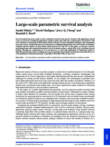
GraphicalrepresentationAll possible combinations of pairs of voltage andcurrent values for either equivalent circuit modelcan be represented as the line through the points(V 0, ISC ) and (VOC , 0).IISCVVOCP. R. NelsonFall 2010WhatToKnow —- – p. 38/46
SuperpositionA voltage or current in a linear circuit is thesuperposition (sum) of the results for eachsource alone.Superposition can be used along with paralleland series resistors, voltage and current dividers,and Thèvenin and Norton equivalent circuits tosimplify the analysis of a circuit.Superposition often gives solutionsin a mathematical form that enhancesintuition.P. R. NelsonFall 2010WhatToKnow —- – p. 39/46
SuperpositionExampleR1 Vx R2IyI2 R3Find the current I2 using superposition.Solve for the current I2 withIy 0 so that Vx is the only sourceVx 0 so that Iy is the only sourcethen add the results.P. R. NelsonFall 2010WhatToKnow —- – p. 40/46
SuperpositionExample - VSet Iy 0 and solve for the current I2V .R1 Vx R2I2V R3P. R. NelsonFall 2010WhatToKnow —- – p. 41/46
SuperpositionExample - VSet Iy 0 and solve for the current I2V .R1 Vx I2V R2I2V R3R3R1 R2 R1 R3 R2 R3P. R. Nelson VxFall 2010WhatToKnow —- – p. 41/46
SuperpositionExample - I, ResultSet Vx 0and solve forthe current I2I .R1R2IyI2I R3P. R. NelsonFall 2010WhatToKnow —- – p. 42/46
SuperpositionExample - I, ResultR1Set Vx 0and solve forthe current I2I .I2I R2 IyI2I R3R1 R3R1 R2 R1 R3 R2 R3P. R. Nelson IyFall 2010WhatToKnow —- – p. 42/46
SuperpositionExample - I, ResultR1Set Vx 0and solve forthe current I2I .I2I I2 R2 R1 R3R1 R2 R1 R3 R2 R3R3R1 R2 R1 R3 R2 R3IyI2I R3 Iy(Vx R1 Iy )P. R. NelsonFall 2010WhatToKnow —- – p. 42/46
Dependent SourcesCircuits containing dependent sources are solvedby the same methods used for other circuits.There is one extra step, because the final resultcannot contain the dependent variable!Not eliminating the dependentvariable from the final result isanother of the most commonerrors I see in student work!P. R. NelsonFall 2010WhatToKnow —- – p. 43/46
Dependent SourceExampleR1 Vx R2BV2 V2 R3 V3 Find V3 .P. R. NelsonFall 2010WhatToKnow —- – p. 44/46
Dependent SourceExampleR1 Vx R2BV2 V2 R3 V3 Find V3 .Hint: The answer may only containVx , R1 , R2 , R3 , and B.P. R. NelsonFall 2010WhatToKnow —- – p. 44/46
Dependent SourceExample - Eqn’sR1 Vx R2BV2 V2 R3 V3 Find V3 .P. R. NelsonFall 2010WhatToKnow —- – p. 45/46
Dependent SourceExample - Eqn’sR1 Vx R2BV2 V2 R3 V3 Find V3 .V2 Vx V2V3 0R1R2 R3P. R. NelsonFall 2010WhatToKnow —- – p. 45/46
Dependent SourceExample - Eqn’sR1 Vx R2BV2 V2 R3 V3 Find V3 .V2 Vx V2V3 0R1R2 R3 V2 B V2 V3 0P. R. NelsonFall 2010WhatToKnow —- – p. 45/46
Dependent SourceExample - ResultR1 Vx R2BV2 V2 R3 V3 Find V3 .V3 VxR1hR1 R2(1 B)R1 R2 1R3iP. R. NelsonFall 2010WhatToKnow —- – p. 46/46
Basic Circuit Concepts All circuits can be analyzed by many methods. Some methods have specific advantages for calculating a particular result in a specific circuit. Some methods yield useful intuition about circuit behavior. No single analysis method will be the best for all possible circuits! P. R. Nelson Fall 2010 WhatToKnow —- - p. 2/46
![[ST] Survival Analysis - Stata](/img/33/st.jpg)