Transcription
SHOP MANUALMASSEY-HARRISPONYfOfher mode/s hegîn on page MH-40)IDENTIFICATIONTracter sériai number is located on plate on right side of front frame,above front axle.Engine sériai number is located on left side of cylinder block.BUILT IN THESE VERSIONSAdjustable Axle—Sériai Nos. PGA 1001 & Up.Standard Axle—Sériai Nos. PGS 1001 & Up.Massey-Harris "Pony"I N D E X (By Starting Paragraphs)BELT PULLEY.64ENGINE CONT.BRAKES.61Oil seal (front)Oil seal (rear)26.41Piston ringsPiston pins2324POWER LIFTAdjustment.35Piston & rod removalTiming gears2119ValvesValve guides & springs1214Valve seatsValve aul .CARBURETORCOOLING SYSTEMFan18GOVERNORAdjust . . ,.3654ENGINECam followers.15CamshaftConnecting rods & bearings.20FINAL DRIVE.24Axle shaftsBull gearsBull pinionsCrankshaftCylinder head.11FlywheelIgnition timing.38.25595960.27Main bearings.25Oil pumpOil pressure.29.30FRONT SYSTEMAxle main memberSteering knucklesSteering linkage142Control valveCylinderPumpTrouble shooting .70.71.71.73.72POWER TAKE-OFF.65REAR AXLE.59STEERING GEARAdjustmentOverhaul. .TRANSMISSIONBevel pinion shaftInput shaftReverse idlerShifter rails. 5. 9.51.52.53.48
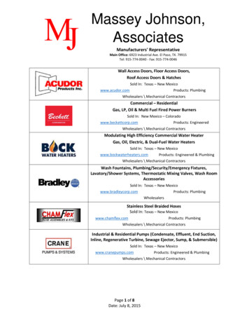
MASSEY-HARRIS PONYService DataCONDENSED SERVICE DATAMassey-Harris PonyEngine MakeEngine ment—Cubic InchesCompression Pressure at Cranking Speed.GENERAL. ContinentalCompression RatioPistons Removed From: . .N62Main Bearings, Number of.4Main Bearings, Adjustable.2%Rod Bearings, Adjustable .Cylinder Sleeves.62Forward Speeds90-110Generator & Starter Make.6.46:1. ., . Below2No,No. . . . None3. Auto-LiteTUNE UP.1,3,4,2. . .012C45 .Auto LiteI.A.D.0.020TC10Firing OrderValve Tappet GapValve Seat AngleIgnition Distributor Make .Ignition Distributor Model .Breaker GapRetarded Timing, Deg.Full Advance Timing, Deg.Mark Indication:Retarded TimingFull Advance Timing.Paint, TC. . . . NoneMark LocationSpark Plug Make . . . . . .ModelElectrode GapCarburetor MakeModelFloat SettingEngine Low Idle rpm. . .Engine High Idle rpm. .Engine Loaded rpm . . .Belt Pulley Loaded rpm.PTO Loaded rpm . . " . . . . Flywheel. Champion8 ES-CLEARANCESCrankshaft Journal DiameterCrankpin DiameterCamshaft Journal Diameter, Front & Center.Camshaft Journal Diameter, RearPiston Pin DiameterValve Stem DiameterCompression Ring WidthOil Ring WidthMain Bearings, Diameter Clearance1. Adjustable front axle2. Tractor front frame(Clearances in thousandths)Rod Bearings, Diameter Clearance. .1.9995Piston Skirt Clearance.1.4995Crankshaft End Play. . .1.746Camshaft Bearing Clearance.1.246Cooling System—Gallons, .0.5434Crankcase Oil—Quarts.5/16Transmission & Differential—Quarts.3/32Final Drive, Each—Quarts.3/16Add for BP and PTO—Quarts.1.5-2.0Fuel Tank—GallonsF/g. MH1— Left s/de view of /Massey-Harr/s Pony Tractor3. Torque tube & clutch housing5. Frame side angle4. Frame cross angle6. Transmission-differential7. Final drive housing8. Wheel axle shaft.1.5-2.0.1.5. . . . 3-7.3-4.5.1 4/54.3 3/5.1 1/2.3/4.6 4/5
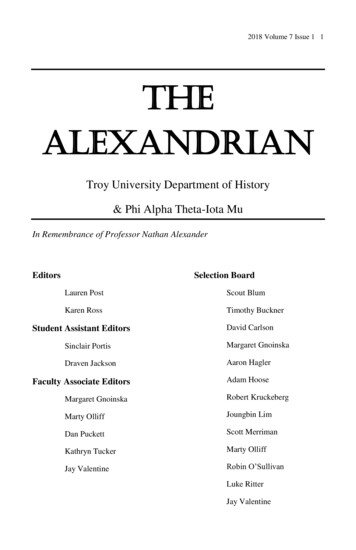
MASSEY-HARRIS PONYParagraphs 1-9FRONT AXLEAXLE MAIN MEMEER1. On standard or non-aajustableaxle, to renew thé main member, jackup imder torque tube and removesteering arms and Woodruff keys fromupper ends of knuckles. Remove eachknuckle, hub and wheel as a singleunit. Remove cotter key from radiusrod pivot boit (at rear end of radiusrod) and unscrew pivot boit. Removecotter key from axle main memberpivot pin and drive pin out rearward.Fig. MH2-Pony adjustable front axleand linkage.1.2.3.4.5.6.7.8.Steering armsTie rodsBellcrankMain memberDrag linkExtension clampSteering knuckleFelt oil sealFor removal of main member of adjustable axle, each outer extensionarm, knuckle, hub and wheel may beremoved as a single unit.STEERING LINKAGENon-Adgustable Axle2. A non-adjustable drag link withintégral socket ends is used and attaches to left steering knuckle arm.The single tie-rod has adjustablesocket ends for obtaining correct toein of front wheels, which should be %inch.Adjustable Axle3. A non-adjustable drag link withintégral socket ends attaches to bellcrank (3-Fig. MH2) which pivots ona shouldered boit in front frame (orsupport to engine). Two tie-rods (2)with adjustable socket ends attach tothé bellcrank and to steering knucklearms(l). Correct toe-in of % inch isobtained by adjusting thé tie-rods attheir inner ends. Outer ends of tie-rodsextend to coordinate with main member extension arms.STEERING KNUCKLES4. REBUSH. Jack up under axle andremove each wheel and hub as a unit.Remove steering arms and Woodruffkeys from upper ends of steeringknuckles and withdraw knuckles fromaxle. Drive thé worn bushings out ofaxle main member (or extension armin thé case of adjustable axles) andinstall new bushings. Ream or honebushings to allow I&T recommendedclearance of .002-.004. Diameter ofnew steering knuckle journal is 1.125inches.S T E E R I N G GEAR5. ADJUSTMENT. Adjustment ofRoss cam and lever steering on théPony tractor is done with thé rightside panel removed as in Fig. MHS.Ail adjustments are made with frontwheels raised or with drag link disconnected to relieve load on steeringmechanism.6. CAM SHAFT. To adjust cam orsteering shaft bearings, loosen steering column clamp (1) and remove théthree cap screws (3). Note that oneof thèse cap screws has a copper washer under its head; replace in sameposition. Raise cover and separate oneshim (4) from pack; split shim andremove it. Replace cover and capscrews and test for end play of bearings. Ail end play should be removed,but there should be no drag on steering gear except through its mid-position and then only when lever shaft isin correct (zéro backlash) adjustment.7. LEVER SHAFT. Loosen lock nuton lever shaft screw (6) and turn screwin until slight drag is felt when steering wheel is turned through its mid-position (front wheels raised).8. PITMAN ARM. To synchronizesteering gear to front wheels whenreinstalling pitman arm on cam levershaft, first place front wheels in theirstraight ahead position; turn steeringwheel through its full range and countthé complète number of turns, thenturn back exactly halfway so that gearis in its mid-position (that is, camlever stud is on high point of cam).Now, install pitman arm and drag linkwithout disturbing position of steering gear or front wheels.9. O V E R H A U L . To remove Rosssteering gear unit for overhaul, it isnecessary to pull pitman arm or disconnect drag link, remove both sidepanels and top panel (through whichsteering column protrudes) and disconnect throttle - to - governor rod.Throttle quadrant assembly can beremoved from gear unit after unit isremoved from tractor.Renew ail worn parts in unit. Thetwo lever shaft bushings should behoned to provide .002-.003 clearancefor lever shaft. Adjust unit after reassembly.F/0. MHS—Pony steering gear adjustment.1. Steering column4. Bearing adjustingclampshims2. Clamp boit5. Housing side cover3. Housing cover cap6. Lever shaft adjustscrewsing screw
Paragraphs 10-14MASSEY-HARRIS PONYENGINE AND COMPONENTSR&R ENGINE WITH CLUTCH10. To remove engine and clutchunit, remove hood, grille and radiator.Disconnect choke wire at carburetorand fuel line at shut-off valve andgovernor spring at governor levershaft; remove forward manifold studnut and lift governor rod support offstud. Disconnect oil gage line fromoutlet at right side rear of cylinderblock. Disconnect electrical harness,namely battery and field connectionsat generator cutout relay and ignitionwire at coil. If tractor is equipped withlights, disconnect from wire harness.On models equipped with hydrauliclift, disconnect or remove hydrauliclines from pump. Support engine in ahoist and remove engine-to-frontframe bolts and engine-to-torque tubebolts. Lift engine and clutch forwardand out of front frame and torque tube.Reinstall engine in reverse manner,rocking slightly to guide clutch shaftinto driven member and pilot bearing.CYLINDER HEAD11. Removal of cylinder head requires removal of hood and drainingcooling system. On hydraulic lift models, remove hydraulic pump and réservoir unit. The air cleaner-to-carburetor tube must be removed and whencylinder head cap screws are takenout, thé air cleaner is taken of andcoil, ignition harness and oil filteris laid back out of way. When reinstalling head, use thé proper lengthcap screws in each hole and tightencap screws evenly from center outward, applying thé correct torque of37.5-42.5 foot pounds.Exhaust face angle44 Intake face angle45 Refer to Standard Units Section forvalve rotator maintenance.VALVE SEATS AND INSERTS13. Valve seats should be refinishedto 45 degree angle and thé widthshould be reduced to inch. Valveseat inserts are supplied for service.Chili insert in kérosène and dry icethen measure outside diameter ofsame. To install inserts, counterborecylinder block to same diameter aschilled insert and install same witha suitable arbor. Peen block near rimof seat recess to lock insert in place.Rennish insert seat to 45 degree angleand - % inch width.VALVE GUIDES AND SPRINGS14. Guides in this model are straightwith no shoulder. When valves areout, guides can be driven downwardinto valve chamber with a suitablearbor. Top of each guide should beff inch below gasket surface of cylinder block. Ream guides, after installation, to provide stem-to-guide clearance of .0035 inch for exhaust valvesand .0018 inch for inlet valves. The additional clearance required for thé exhaust valve is provided for on exhaustvalve stem, hence thé same reamermay be used in both exhaust and inlet guides.Test valve springs and renew anywhich do not test 15 pounds plus orminus 2 pounds when compressed to1% inches, or which are rusted, distorted or do not hâve protective coating. Valve spring free length is 1-ffinches.F/g. MH4—Continental N 62ex»haust and inletvalves. Valve ro»fafors are u s e don exhaust valvesonly.1.2.3.4.5.6.7.8.9.10.Valve springExhaust valveSpring retainerSplit cône locksRoto capInlet valvePin type lockTappet screwLock nutTappet barrelVALVES12. Exh. valves in this engine hâveRoto caps on their stem ends (Fig.MH4) to provide a rotating motioneach time valve is lifted. This causesa wiping action between valve faceand its seat and permits longer valvelife. To remove valves, remove hood,cylinder head, carburetor, distributorand valve chamber cover. Stuff smallbits of cloth in oil return holes invalve chamber to prevent droppingvalve spring keepers into crankcase.Compress valve springs and removekeepers (exhaust valves hâve splithalf-moon keepers and inlet valveshâve pins). Lift valves out of guidesand springs; take retainer seats andRoto caps out of chamber. Renewvalves if stem diameter is less thanthé values given below.Exhaust stem diameter3124Inlet stem diameter3141Valve seat angle (in b l o c k ) . . . .45 F/g. MH5—Adjusting tappefs on Continental N62 engine. A three wrench opération.
MASSEY-HARRIS PONYParagraphs 15-19just ail of thé tappets it will be necessary to remove carburetor, distributor and valve chamber cover. Ifonly one or two tappets near thé rearof block are to be adjusted, thé distributor need not be removed. Adjusttappets for number one cylinder whennumber four piston is at top center ofits compression stroke; adjust numberthree when number two piston is ontop center of its compression strokeand proceed in thé same manner forail cylinders through thé firing order(1-3-4-2).Fig. MH6—Continental N62 timing gearsand valve timing marks. Oversize marking on cam gear corresponds with 7 -jmark on gear case gasket surface.VALVE TAPPETS(CAM FOLIOWERS)15. The barrel type tappets can berenewed without disturbing thé camshaft or cylinder head by first removing thé valve chamber cover, screwing thé tappet adjusting screw completely down and removing thé valvespring. While holding thé valve up,remove tappet screw and lock nutfrom barrel and lift thé barrel out ofits bore. Oversize tappets are not provided for service. I&T recommendedclearance of tappet in its bore shouldnot exceed .0025 for quiet opération.Note: If ail valve tappets are to beremoved, it is recommended that thécylinder head and valves be removed.16. ADJUST. Adjustment of tapperclearance is a three-wrench opération(Fig. MHS). Recommended gap is .012cold for inlet and exhaust. To ad-VALVE TIMING17. To check thé timing when engirie is assembled, set exhaust valvetappet of number 1 or 4 cylinder to.020 clearance. Crank engine until thépiston of cylinder being checked (1 or4) is coming up on its compressionstroke and continue to crank slcwlyuntil exhaust valve closes and tappetcan be rotated with thé fingers. At thispoint, thé painted mark on flywheel(indicating top center) should alignwith. thé timing pointer when viewedthrough timing inspection hole inright side of engine or within 4 degrees or inch either way.If valves are incorrectly timed, remove timing gear cover and inspectrelation of timing marks on camshaftgear and crankshaft gear. The punchmarked tooth of crankshaft gear ismeshed between thé two punchmarked teeth of camshaft gear.TIMING GEARS AND COVER18. TIMING GEAR C O V E R . Tocheck timing gears (without removalof same), to renew crankshaft front oilseal or to remove and reinstall governor assembly for overhaul, thé timinggear cover can be removed withoutdraining and removing radiator onFig. MHZ—Puf/ing Continental N62 cam gear. Note washer foefween camshaff and pu//erscrew fo profecf governor p/unger bore. Tappets are he/d up by vv/re under heads offappef screws.models not equipped with hydrauliclift. However, on models equipped withhydraulic lift, it will be necessary toremove radiator. First, remove hood.grille and crank support. Take offfan belt and fan assembly; removestarting jaw nut and pull thé crankshaft pulley. Disconnect governor linkage and remove cap screws and nutsattaching cover to engine and oilpan. Loosen ail other oil pan capscrews and insert a thin knife bladeor feeler between oil pan gasket andtiming gear cover and separate thétwo. Pry cover ofî its dowels andstuds. Timing gears may now be inspected; governor weights assemblycan be removed from camshaft gearand governor lever shaft and associated parts in thé cover can be inspected or repaired as required; crankshaft front oil seal (a spring loadedleather seal with lip facing inward)can be pressed out of cover and renewed.19. TIMING GEARS. If thé gears areto be removed, camshaft removed orcrankshaft end play adjusted, théradiator must be drained and removedin addition to thé work performed inthé preceding paragraph. As will benoted in Fig. MH6, thé timing gearsare meshed so that thé punch markedtooth of crankshaft gear is betweenthé two punch marked teeth of camshaft gear.To remove camshaft gear, take outthé four machine screws fasteninggovernor weights assembly to thégear. Remove weights assembly andcamshaft gear nut. To remove gearwithout using a puller, rotate camshaft until thé two % inch holes ingear hub are in register over shaftthrust plate retaining screws. Inserttwo %-16 screws having ll/2 inchthreaded portion into gear hub holesand turn them in evenly until gear ispushed off shaft. An alternate way isto use puller as shown in Fig. MH7,being careful that governor plungerbore in camshaft is not damaged bycenter leg (screw) of puller.To remove crankshaft gear whencover is off, it will be necessary touse a suitable puller.Note markings (Fig. MH6) ongear cover gasket surface of crankcase. This indicates correct oversizeor undersize gear to be used in thisblock. In this instance, it indicatesthat camshaft gear one size overstandard should be used. The gearwill be similarly marked on its forward face.When installing thé camshaft gear,it is advisable to remove distributoror oil pan and buck up thé shaft.
MASSEY-HARRIS PONYCAMSHAFT20. To remove camshaft, removetiming gear cover. radiator and camshaft gear. Remove cylinder head andblock up valves. Raise tappets andhold them up with wire placed underheads of tappet screws. Remove thrustplate and thé camshaft from its bores.Camshaft has three bearing journals which rotate in bores eut in thécylinder block; no bushings being usedor supplied for service. A bore in rearof camshaft carries thé slotted oilpump drive shaft. A pin is rivetedin thé camshaft and passes throughthis rear bore, thé slotted end of oilpump drive shaft engages this pin andis driven by it. A bore in thé forwardend of camshaft receives thé governorplunger (cup and shaft assembly) asshown in Fig. MHS. A relief hole isdrilled just aft of front journal torelieve any pressure created by actionof pluriger. This hole should be freeof dirt and sludge. Dimensions of anew camshaft are as follows:Front & center journal: 1.7455-1.7465Rear journal:1.2455-1.2465Inlet valve lift:241Exhaust valve lift :243Recommended clearance of camshaft in thé block bores is .003-.0045.lf thé bearing clearance exceeds .0007,it will be necessary to renew thé camshaft and or cylinder block, or tomake up and install bushings. Camshaft end play is controlled by athrust plate behind thé camshaft gear,Renew thé thrust plate if thé endplay exceeds .007.Paragraphs 20-25available. Taper compression rings areinstalled with thé side marked "Top"facing up.Fig. MHS-Continental N62 camshaft withgovernor plunger in position. Hole aft offront journal is for relief of vctcuutn orpressure created in governor plunger bore.move pistons as described in precedingparagraph.If new rings are to be installed, thécylinder head should be removed andthé unworn ridge at top of cylinderseut out to protect piston rings frombreakage or flutter. Fit of piston incylinder is checked with V2 inch widefeeler placed between piston skirt andcylinder wall at right angle to thépiston pin (thrust side of piston skirt)as shown in Fig. MH9. A pull of 5-10pounds should be required to pull a.0015 thick feeler from between pistonand cylinder wall.PISTON RINGS23. Measure gap of rings in worncylinder at lowest (unworn) portionof cylinder. Correct gap is .007-.012for ail rings. Check side clearance ofrings in their grooves (after carbonis removed), Clearance for compression rings is .0015-.0035 and for oilcontrol rings is .001-.0025. Piston ringsof .020, .030, .040 & .060 oversize areCONNECTING RODS AND BEARINGS, PISTON PINS ANDBUSHINGS24. Précision insert type conn. rodbearings can be renewed after removalof thé oil pan. Desired clearance ofbearing on thé crankpin is .0015-.002.Undersize inserts of .002, .020 and .040are available. Check rod for side playon crankpin (.006-.010) and if insufficient investigate for a mis-alignedrod, or burrs on side of rod or crankpin journal.Piston pins are solid type, full flaating and retained in piston bosses byspring steel lock rings. An applicationof heat to thé piston or submergingpiston in hot oil or water will facilitate removal and reinstallation of pin.Use new lock rings whenever old oneshâve been disturbed. If oversize pins(.003, .005 or .010) or new bushingsare to be installed, fit them by reamingor honing. The .5433-.5435 diameterpiston pin should be a light push fitin piston and should hâve .0003 clearance in thé rod bushing. Align connecting rods whenever new pins orbushings are installed.CRANKSHAFT AND MAINBEARINGS25. Crankshaft is mounted in twoprécision, insert type bearings whichmay be renewed without removingROD AND PISTON UNITS2l. Connecting rod and piston assemblies are removed from below. Thelower end of each cylinder is chamfered to facilitate installation of pistons and rings from below without using a ring compressor. An alternatemethod (providing cylinder head hasbeen removed) is to install rod andpistons from below without thé rings;then push pistons up through boreand out thé top. Install rings on pistonand use a compressor to guide pistonand rings into bore. Rod spurt hole,numbers on side of rod and cap facetow r ard camshaft side of engine. Onaluminum pistons, split in skirt îsplaced away from camshaft. TightenConnecting rod cap bolts to 20-25 footpounds.PISTONS AND CYLINDERS22. Cast Iron pistons were originally used in this engine, but présent production uses aluminum pistons. Pistons are available in standard size andoversizes of ,020, .030, .040 & .060. Re-Fig. MH9—Fitting Continental N62 piston. Use Y2 inch wide feeler, ,0075 thick. Correctfit requ/res 5 - Ï O pounds pull.
Paragraphs 25-30MASSEY-HARRIS PONYRenewal of seal requires splitting thétractor as described in Clutch sectionand removal of clutch and flywheel.When removing seal retainer, use athin knife blade or feeler to separateoil pan gasket from thé retainer. Pressnew seal in retainer so that lip willface towards inside of engine. Installseal carefully using oil to lubricate lipand make guide sleeve to guide it overcrankshaft flange,Fig. MHIQ—Adjusting crankshaft end playon Continental N62. Shims (4) are variedto obtain .003-.007 end play. Locatebronze washer (3) on dowels (5) beforedriving thrust plate (2) and crank gear (1)in position,crankshaft or engine. Desired clearance of crankshaft in thèse bearings is.0015-.002 inch. Crankshaft journalssizes and wear limits are as follows:Mains journal diameter. . . .1.999-2.000Main bearing oil clearance. .0015-.002Repair if clearance exceeds0032Crankpin diameter1.499-1.500Renew or regrind shaft ifjournals or pins out-ofround more than003Main bearing cap nuttorque92.5-97.5 ft. Ib.Undersize bearings of .002, .020 and.040 are available for service.Crankshaft end play of .003-.007 iscontrolled by shims between thrustplate (2-Fig. MH10) and front journalof crankshaft. To reduce end play, rernove timing gear cover and camshaftgear. Pry ofï thé crankshaft gear (1),thrust plate (2) and remove shims(4) as necessary to reduce end play.Shims are .002 and .008 thick. To recheck end play with timing gear coverofï, thé crankshaft pulley must be inplace and thé starting jaw nut tightened. Be sure thé punch marked toothof crankshaft gear is meshed betweenthé two punch marked teeth of camshaft gear when reassembling.CRANKSHAFT REAR OBI SEAL26. Crankshaft rear seal is a springloaded type, pressed into a retainerwhich is fastened to thé rear of cylinder block as shown in Fig. MH11.8FLYWHEEL27. Flywheel may be removed aftertractor is split and thé clutch removedas described in Clutch section. Thereis no need to mark relative position offlywheel to crankshaft flange as it canbe installed in one position only. Flywheel run-out should not exceed .004at rear face. Flywheel ring gear is renewable and should be shrunk on flywheel with bevel of teeth towards thérear for easy engagement of starterpinion gear.OIL PAN28. The sheet métal pan is fastenedto crankcase by cap screws. Removalof pan is complicated in early production models by thé front axle pivotpin and tractor must be blocked upunder forward end of torque tube andpivot pin removed before pan can belowered. When reinstalling pan, takecare when inserting thé rear capsereins as it is possible to drop thèseinto flywheel housing and their removal jrom this compartiment is difficult and may ' sometimes requiresplitting tractor at this point.OIL PUMP29. Pump is located on thé rear machined surface of cylinder block asshown in Fig. MH11. Pump is drivenby thé camshaft. Removal of thé pumprequires splitting thé tractor as outlined in Clutch section and removal offlywheel. A 0.007 thick lead gasket (8)is located between pump body (9) andcover plate (5). Between cover plateand engine is another gasket made ofvellumoid. Idler gear shaft (10) is apress fit in thé body; diameter of newidler shaft is .501. The body bore fordrive gear and shaft assembly (7) coutains bronze bushing (11); if bushingis worn it is recommended that newpump body with bushing be installed,Diameter of new drive gear shaft is.4985. Thickness of new drive gear oridler gear is .3735. Check pump forgear backlash which should not exceed 0.005. Gear to pump body sideclearance should not exceed 0.004.OÏL PRESSURE RELIEF VALVE30. The valve assembly is located inright side of cylinder block. Valve isspring loaded, plunger type, maintaining oil pressure of 20-30 pounds at op-Fig. MHTI—Continental N62 oil pump cissemhly and crankshaft rear oil seal. Repairson thèse units require removal of cfufcfi and flywheel.1.2.3.4.Oil seal retainerOil sealCrankshaftflaîigeClutch shaft pilot bushing5. Pump cover & gasket6. Idler (driven) gear7. Driving gear & shaft8.9.10.11.Body-to-cover gasketOil pump bodyIdler gear shaftDrive shaft bushing
MASSEY-HARRIS PONYParagraphs 30-36erating speed. Two types of reliefvalves hâve been used in thé Ponytractor. In engines up to sériai number 6138, a bullet nose plunger, M-Hpart number 1500066M1 is used; engines with sériai number 6138 and upcontain thé cylinder type plunger,M-H part number 15322A. Relief valvespring, M-H part number 21195A(painted red) should be used to obtain correct oil pressure setting.CARBURETOR34. OVERHAUL G O V E R N O R . To31. Marvel-Schebler updraft carburetor model TSV16 or model TSV24 isused. Adjustments on thé TSV carburetor are limited to idling speed andidling mixture adjustments. Bothshould be performed when engine iswarmed to operating température.Idling speed is 500 rpm. Float settingis 1A inch and is measured from nearest face of float to gasket surface ofbowl cover. Refer to Standard UnitsSection for additional data.GOVERNOR32. SPEED ADJUSTMENT. To ad-just maximum no-load governed speed,remove right side panel which exposeslower portion of throttle quadrant assembly as shown in Fig. MH12. Changethé governor spring tension by turning bail and socket joint (S) on governor rod until desired speed is obtained. If engine surges at no-loadspeed, turn in on bumper screw (D)unti] surge is eliminated (this willcause slight increase in no-load speed).Correct governed speeds follow:Crankshaft rpm (Load)(No Load)Belt Pulley rpm (Load)(No Load)Power Take-Off rpm (Load)(No Load)33. L I N K A G E ADJUSTMENT. Tocheck or set ail linkage, first adjustcarbureior-to-governor rod (R) sothat there is inch clearance betweenthrottle lever and its wide open stopat (G) when governor lever is in wideopen position. Turn bumper screw (D)out so it is inoperative. Check to seethat ail linkage opérâtes freely; thenstart engine and warm to operatingtempérature; then adjust as outlinedin preceding paragraph.1800205019902266540615D.G.R.S.remove governor, first remove timinggear cover as outlined under TIMINGGEAR COVER section. Fig. MH13shows position of weights and carrier,plunger and shaft in thé camshaftgear. Fig. MH14 shows governor levershaft and bumper spring and screwin timing gear cover. Inspect weightsand pins for wear; also check weightsfor amount of wear on their plungercontacting surface. Inspect plungerfor wear on its shaft and also onweight-contacting surface of its cup.If lever shaft bearing iri timing gearcover is worn, remove thé rivet whichattaches arm (1-—Fig MH14) to levershaft, take out cotter pin (2) and pulllever shaft from cover. Note that asteel bail is located in lower bore ofcover; bottom of lever shaft rests onthis bail. The worn bearing may bedriven out of upper bore in cover andrenewed. Renew thé felt seal also. Ifbumper spring (5—Fig. MH14) is loosein cover, rerivet it in place.If a newly overhauled governor doesnot operate properly, check for aplugged pressure relief hole in thécamshaft. Refer to paragraph 20.COOLING SYSTEMF/g. A1H73—Fony timing gears, sfiowingposition of governor weights and carrier,attachée! fo camshaft gear.its adjusting strap. Fan assembly canbe removed from tractor after hoodand fan belt hâve been taken ofï. Radiator need not be disturbed on modelswithout hydraulic lift. Parts for servicing thé fan assembly are not supplied;thé complète unit is renewed if repairsare required.RADIATOR36. Tanks & core of radiator assembly are not détachable. Radiator ismounted to thé tractor by two supports(formerly a one-piece unit) which arefastened to each side of radiator. Onlater Pony models, a pressure type capis used. Radiator may be removed after hood and grille hâve been taken off.FAN ASSEMBLY35. Adjust fan belt to thé correcttension by moving thé generator onBumper screwThrottle lever stopCarburetor to governor rodBail and socket jointFig. MH14—Pony governor lever shaft assemhly in timing gear cover.Fig. MH 12—Pony governor linkage assembly.1. Arm3. Control lever2. Cotter pin4. Bumper screw5. Bumper spring
Paragraphs 37-43MASSEY-HARRIS PONYIGNITION SYSTEMCLUTCH37. Three models of Auto-Lite distributors are used on Pony tractors;IAD 4028A, IAD 60032A or IAD 60032G. The distributor is mounted onright side of engine. Condenser is located within thé distributor. Breakerpoint gap is .020. For overhaul andtesting procédure refer to StandardUnits section.41. ADJUST. To adjust thé clutchpedal travel, refer tô Fig. MH16 andadjust yoke (Y) on rod (R) until clutchpedal has a free travel of approximately one inch.38. IGNITION TIMING. To time ignition with distributor installed, crankengine until number one piston iscoming up on compression and continue to crank slowly until paintedmark on flywheel (Fig. MH15) alignswith timing pointer when viewedthrough inspection opening on rightside of engine; number one piston isnow at top center of its compressionstroke. Turn ignition switch on androtate distributor a few degrees clockwise; hold number one spark plugwire close to head or grounded pointand very slowly rotate distributorbody counter-clockwise until a sparkoccurs at end of plug wire; lock distributor in position. To recheck ignition with timing light, operate engineat idle speed (do not operate above 600rpm, as automatic advance starts atthis speed) and make check with timing light connected in séries witheither number one or number fourspark plug wire. If timing is correct,thé light will flash at thé same instantthat painted mark on flywheel alignswith timing pointer. If thé two do notalign as light flashes, rotate d
crank (3-Fig. MH2) which pivots on a shouldered boit in front frame (or support to engine). Two tie-rods (2) with adjustable socket ends attach to thé bellcrank and to steering knuckle arms(l). Correct toe-in of % inch is obtained by adjusting thé tie-rods at their inner ends. Outer en