Transcription
/UDC621 .753 .1: 621 .7 : 621 .9 : 744 .43DEUTSCHE NORMApril 1991General tolerances for Iinearand angulardimensions and geometrical .tolerancesDIN7168(not to be used for .new destgns) .'-j' ;,,Allgemeintoleranzen ; Langen- and Winkelma8e,Form and Lage& '(nicht fur Neukonstruktionen)'. .'7' 1Supersedes May 1981edition of DIN 7168Part 1 and July 1986This standard is not to be used for new designs . General tolerances for these are now covered by ISO 2768 Parts 1 and 2 .See also clause 1 and the Explanatory notes .In keeping with current practice in standards published by the International Organization for Standardization (ISO), acomma has been used throughout as the decimal marker .mm-1 ScopemThis standard is intended to ensure that all drawingsprepared to date in which general tolerances have beenspecified on the basis of DIN 7168 will remain intelligibleand be interpreted correctly, and also to inform the user ofthis standard that, for all new designs, tolerances are to bespecified on the basis of ISO 2768 Parts 1 and 2 .01aE xmZ mo W9m2table 2) ;b) angular dimensions (cf . table 3), both those indicatedand those not usually indicated on drawings, such as 90 assembled parts :d) workpiece features for which no individual tolerances ofform and position are indicated .applicable for the dimensions of parts produced by metalmremoval (i .e . chip removal)'), unless this involves specia!vmanufacturing processes for which other standards speci-General tolerances as specified in this standard do notapply for :ao.fying general tolerances apply .E z C,mma) linear and angular dimensions and workpiece featuresGeneral tolerances as specified here shall apply whenfor which tolerances have been individually indicated ;o 5c cCLreference is made to this standard in drawings or associated documents (e .g . delivery conditions) in accordancem 0- m b) linear and angular dimensions and workpiece featuresfor which other standards on general tolerances arewith clause 5 .specified in drawings or associated documents ;mIf special general tolerances are specified in accordanceL Cmwith other standards (cf . page 6), the standards concerned r v mdocuments . If, in cases where production specificationso c . m0contain references to more than one standard on general3external radii and chamfer heights for broken edges (cf .Field of applicationGeneral tolerances as specified in this standard are osizes, step sizes, diameters, clearances (cf . table 1),angles or the angles of regular polygons : Ca) linear dimensions, such as external sizes, internalc) linear and angular dirrfeensions produced by machiningmvm m zIGeneral tolerances as specified in this standard apply for :c) auxiliary dimensions enclosed in brackets (cf . DIN 406Part 2) ;shall be indicated on the drawing or in the associatedtolerances, there is any doubt as to which standard is toapply for a given linear or angular dimension, then thed) theoretically exact dimensions enclosed in rectangularframes as specified in ISO 1101 ;e) angular dimensions on circular graduations ;f) 90 angles, not indicated on the drawing, between linesstandard specifying the larger tolerance shall be deemed forming coordinate axes :to apply .g)Accordingly, a dimension between an unfinished and a Lfinished surface on a blank (e .g . on a casting blank oroindicated, will be required to meet the general toleranceA0.given in the relevant standard on blanks, provided that islinear and angular dimensions produced by the assembly of parts ;h) workpiece features which are not produced by removalforging blank), for which no individual tolerance has beenof material, in accordance with the indication of a semifinished product on drawings .indeed the larger tolerance . However . for a dimension0Zbetween two finished surfaces, the general tolerancespecified in DIN 7168 shall always apply .Production specifications in which linear or angular dimensions (but not auxiliary dimensions) appear without individually indicated tolerances shall be considered incomplete ifthere is no reference, or inadequate reference, to generaltolerances .') For concepts relating to manufacturing processes . seeDIN 8580 .Continued on pages 2 to 7AftBeuth Verlag GmbH, Berlin, has the exclusive right of sale for German Standards10.91(DIN-Normen).DIN 7168 Engl . Price group 8Sales No .0108 ' '
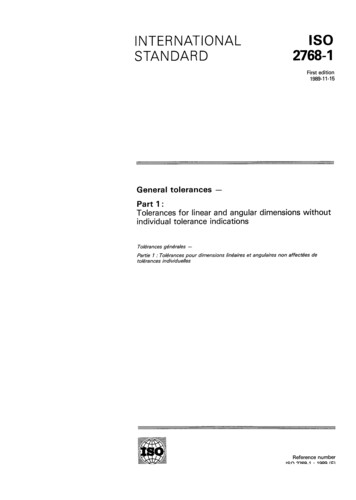
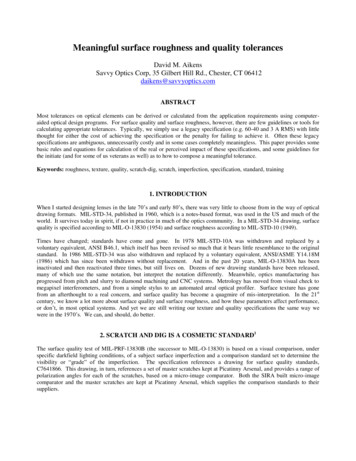
Page 2 DIN 71683General tolerances for linear and angular dimensions3 .1Linear dimensionsTable 1 . Permissible deviations for linear dimensions, except for external radii and chamfer heightsPermissible deviations, in mm, for nominal sizes, in mm,Toleranceclassfrom0,5')to3over3up to6over6up to30over30up to120over120up to400over400up to1000over1000up to2000over2000up to4000over4000up to8000I 0,05over8000up to12000 0,1 0,15 0 .2 0,3 0,5 0,8--over12000up to16000f (fine) 0,05m (medium) 0,110,1 0,2 0,3 0,5 0,8 12 2 3 4g (coarse) 0,15- 0,2 0,5 0,8 1,2 2 3 4 5 6 7 1 1,5 2 3 4 6 8 10 12sg (very coarse)- 0,5I . 5over16000up to20000IIt 6 8 12') For nominal sizes below 0,5 mm, the deviations shall be indicated adjacent to the relevant nominal size .Table 2 . Permissible deviations for external radii, r(cf . figure 1 for example), and chamfer heights, h(cf . figure 2 for example)Table 3 . Permissible deviations for angular dimensionsPermissible deviations, in mm,for nominal sizes, in mm .Toleranceclassf (fine)m (medium)g (coarse)sg (very coarse)from0,5 1 )to3over3up to6over6up to30over30up to120over120up to400 0,2 0,5 12 4.0,2 1 2t4f (fine)Angular dimensionsGeneral tolerances for angular dimensions apply irrespective of the actual dimensions of the lengths, i .e . the angulardeviations may occur both on workpieces with maximummaterial sizes and on workpieces with minimum-materialsizes . The upper and lower deviations do not limit the formdeviations of the legs or surfaces forming the angle .Note . In the case of workpieces exhibiting deviations ofform, the angle is defined by the direction of thestraight lines or planes applied to the two angle legsunder the minimum material conditions (cf .ISO 1101 for the definition of the minimum condition) .4over10over10up to50over over12050up to up to120400T 1 30'1 20'g (coarse) 1 30' 50' i 25'sg (very coarse) 3 m (medium) 8For nominal sizes below 0 .5 mm, the deviations shallbe indicated adjacent to the relevant nominal size .3 .2ToleranceclassPermissible deviations, inunits of angle, for nominalsizes of the shorter leg, in mm,i2 - 1 10'II iover400 5'I15' 1 1 0' 30' 20'General geometrical tolerances4 .1 Tolerancing principle as specified in ISO 8015General tolerances based on the tolerancing principlespecified in ISO 8015 are only to be applied when thedrawing concerned contains the reference 'Tolerancing toISO 8015' . Where that is the case. the general geometricaltolerances (i .e . the tolerances of form and position) applyindependently of the actual local sizes of the workpiecefeature . Each individual tolerance requirement must bemet . The general geometrical tolerances may thus also beapplied even if the features are everywhere at theirmaximum material size . For fits, the envelope requirementmust also be specified, and this shall be individuallyindicated on the drawings (cf . Explanatory notes) .4 .1 .1 General tolerances of form4 .1 .1 .1Straightness and flatnessThe general tolerances on straightness and flatness shallbe as specified in table 4 . Tolerances on straightness shallbe selected from the table on the basis of the length of thecorresponding tine, while, for flatness tolerances, selection shall be based on the longer lateral length of thesurface, or on the diameter of the circular surface .4 .1 .1 .2 CircularityThe general tolerance on circularity shall be equal to thenumerical value of the diameter tolerance, but in no caseshall it be greater than the respective tolerance on radialrun-out given in table 6 (cf . Explanatory notes) .
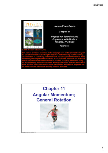
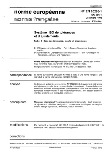
11;1 b. DIN 7168 Page 3C-4LMTable 4 .General tolerances on straightness and flatnessToleranceclassGeneral tolerances on straightness and flatness,in mm, for a nominal size, in mm, ofup to6over 6up to 30over 30up to 120over 120up to 400over 400up to 1000over 1000up to 2000over 2000up to 4000over 4000up to 0,040,080,150,20,30,4-T0,0250,060,120,250,4 . .0,60,912U0,10,250,51,52,53,554.1 .1 .3 CylindricityGeneral tolerances on cylindricity have not been specified .Note . If the envelope requirement is to apply to fits withcylindrical surfaces, the dimension concerned shallbe identified by the symbol , (e .g . 0 25 or25 H7 ([)) .0W*4 .1 .24 .1 .2 .1Table 5 . General tolerances on symmetryParallelismThe limitation of the deviation in parallelism is given eitherby the general tolerances on straightness or flatness (cf .subclause 4 .1 .1 .1), or by the tolerance on the distancebetween the parallel lines or surfaces, whichever is thegreater .Note . If the envelope requirement is to apply to fits with flatmating surfaces, then the dimension concernedshall be identified by the symbol , as specified inISO 8015 (e .g . 30 p, or 30 h 7 ) .4 .1 .2 .2 Perpendicularity and inclinationGeneral tolerances on perpendicularity and inclinationhave not been specified . Instead, the general tolerances onangular dimensions may be applied (cf . subclause 3 .2) .4.1 .2 .3 SymmetryThe general tolerances for symmetrical, but not axiallysymmetrical, features are to be taken from table 5 . Thesegeneral tolerances also apply in cases where one of thesymmetrical features is axially symmetrical and the otheris not.For general tolerances on symmetry, the longer featureshall be taken as the datum . That applies to all featureswhich may be referred to each other . If both features are ofthe same nominal length, then either may serve as thedatum . If, for functional reasons, these datum specifications are not permissible, the tolerance on symmetry shall,be Individually indicated as specified in ISO 1101 .y vr . ;14.1 .Z.4 .'.'Coax] alit ; . -, General tolerances on coaxiality have not been speced .1The,deviatiortniancoaxialitymy i cases be asextreme"!great{as,the ooleranca value for radial run-out given in1,8table 6, since the deviation in radial run-out comprises thedeviation in coaxiality and the deviation in circularity (cf .Explanatory notes) .General tolerances of positionThe longer of the two features shall betaken as the datum . Ifboth features are of the same nominal size, then either mayserve as the datum . If, for functional reasons, these datumspecifications are not permissible, then tho tolerance onparallelism shall be individually indicated as specified inISO 1101 .I4 .1 .2.5ToleranceclassSymmetry tolerance,in mmR0,3S0,5T1U2Radial run-outThe general tolerances on radial run-out shall be a :specified in table 6 . For general tolerances on radial runout, the bearing surfaces shall be taken as the datum, ifthey are designated as such . Otherwise, the longer of thetwo features shall be taken as the datum . If both featuresare of the same nominal size, either may serve as thedatum . If, for functional reasons, these datum specifications are not permissible, the tolerance on radial run-outshall be individually indicated as specified in ISO 1101 .4.1 .2 .6 Axial run-outThe general tolerances on axial run-out shall be asspecified in table 6 .For general tolerances on axial run-out, the bearingsurfaces shall be taken as the datum, if they are designatedas such . Otherwise, each of the axially symmetric featuresmay serve as the datum .Table 6 . General tolerances on radial and axial run-outToleranceclassRadial and axialrun-out tolerances,in mmR0,1S0,2T0,5U1
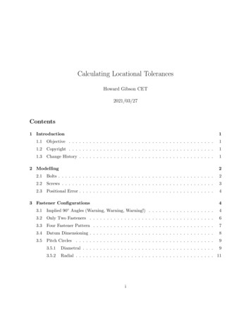
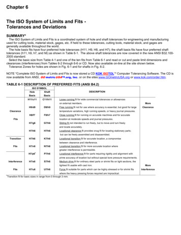
Page 4 DIN 71684 .2Tolerancing principle 'envelope requirement without indication on drawing' as specified in DIN 71674 .2.1General tolerances of formGeneral tolerances of form have not been specified . All deviations in form shall, if no individual tolerances of form have beenindicated, be limited by the dimensional tolerances as follows ./ B/Shaft10 prShaftCylinderIn the case of shafts, the surface of the featureshall not exceed the geometrically ideal form(cylinder) at its maximum material size (envelope requirement), nor shall the actual dimension be smaller than the least material limit atany point./LTolerancei ToleranceeNote . The cylinder at its maximum materiallimit is embodied by the GO ring gauge .Minimum limitof sizeMaximum limit of sizeMaximum limit of sizeCyuncerIn the case of holes, the surface of the featureshall not be smaller than the geometricallyideal form (cylinder) at its minimum materialsize (envelope requirement), nor shall theactual dimension be greater than the maximummaterial size at any point.Tolerance,Tolerance,,Minimum limitl --of sizei ToleranceMaximum limit of size, ; Tolerance-Minimum limitof sizeMaximum limit of size4 .2 .2 General tolerances of position4 .2 .2 .1Note . The cylinder at its minimum materiallimit of size is embodied by the GO pluggauge .ParallelismFor tolerances on parallelism, the specifications given insubclause 4 .2 .1 shall apply analogously .4 .2 .2 .2 Perpendicularity and inclinationGeneral tolerances on perpendicularity and inclinationhave not been specified . Instead, the general tolerances forangular dimensions may be applied (cf . subclause 3 .2) .Note . Previously, the rule was that the deviations inperpendicularity should lie within the dimensionaltolerances . measured in a rectangular system ofcoordinates . In practice . however, this limitationwas and is hardly ever observed in industrybecause it is seldom required for functionalreasons .4 .2 .2 .3 SymmetryFor tolerances on symmetry of non-axially symmetricalworkpiece features, the values specified in table 7 shallapply . These tolerances on symmetry shall also apply torelationships between workpiece features where one of thefeatures is axially symmetrical and the other is not .Table 7 .General tolerances on symmetry for non-axiallysymmetrical wor
4.1 Tolerancing principle as specified in ISO 8015 General tolerances based on the tolerancing principle specified in ISO 8015 are only to be applied when the drawing concerned contains the reference 'Tolerancing to ISO 8015'. Where that is the case. the general geometrical tolerances (i.e. the tolerances of form and position) applyFile Size: 1MBPage Count: 7