Transcription
Mastercam to Mazatrol Post-Processor Tutorial 11/1/2018Mastercam toMazatrol Post-Processor TutorialIntroductionThe following tutorial instructs the user in the approach to programming that allows aMastercam file with it’s associated toolpaths to output the desired Mazatrol code.It is not the intention of this tutorial to teach the use of Mastercam or the Mazatrol conversational system. It is assumed that the user of this product has been instructed inthe use of the former items. We provide in addition to this tutorial both a help fileaccessible when in the Mazatrol Menu by clicking on Help and a Mazak for MastercamManual - For Mastercam instruction please contact your local Mastercam reseller. Formazatrol instruction please refer to your Mazak/ Mazatrol Programming Manuals orcontact your local Mazak representative.Section 1. Programming a Mill PartSection 2. Programming a Lathe PartNote: This text was compiled using Version 8.0.8 of the Mazatrol Product – some dialogspresented may have changed or you may be using either an earlier or later version of thesoftware.1
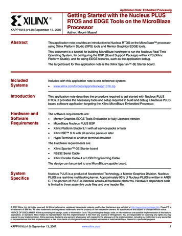
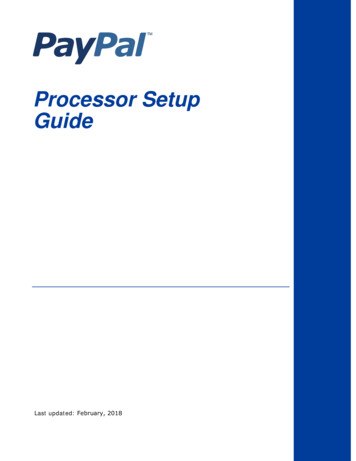
Mastercam to Mazatrol Post-Processor Tutorial 11/1/2018Section 1 - Mill1. Creating simple face and contour toolpathsExercise 1 - Opening the part file1. Choose Main Menu, File, Get2. Navigate to the folder with the tutorial parts.3. Select Mazak 1 Mill.mc9; then choose Open.4. Choose, Main Menu, Toolpaths, Job Setup5. Enter settings as shown.This settingwill be set asINITIAL Z2
Mastercam to Mazatrol Post-Processor Tutorial 11/1/2018Note: Job Setup settings will affect the first line of the mazatrol PNR and MAT i.e. thematerial selected will be output and the Z depth of the material will be output asINITIAL-Z see below:PNR MATINITIAL-Z ATC MODE MULTI MODE MULTI FLG PITCH-X0 IRON 0.7100 1OFFPITCH-YThe other settings will have to be manually entered by the user if desired either using theeditor (if available) or at the control. Also the values for federate and spindle speed thatare set in the mastercam parameter pages will also output to the Mazatrol code.Exercise 2 - Creating Facing Toolpath for outsideprofile1. Choose Main Menu, Toolpaths, Face2. Select outside profile as shown using chain2. Select Done3. Select or Create a 1.5”Dia Face Mill as shown.3
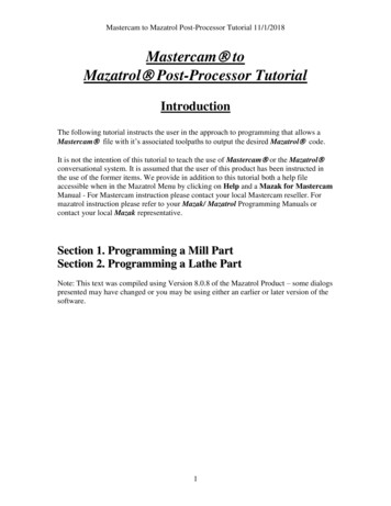
Mastercam to Mazatrol Post-Processor Tutorial 11/1/20184.Click on Misc. Values button and set Face Machining to Face as shown below4
Mastercam to Mazatrol Post-Processor Tutorial 11/1/20185. Click OK when done.6. Click on Facing Parameters Tab and set Values as shown;5
Mastercam to Mazatrol Post-Processor Tutorial 11/1/20187. Click on OK when completed.6
Mastercam to Mazatrol Post-Processor Tutorial 11/1/2018Exercise 3 - Creating Contour Toolpath for outsideprofile1.2.Choose Main Menu, Toolpaths, ContourSelect outside profile as shown using chainSelectChainHere3.4.Select DoneSelect 0.5” Dia Flat end Mill as shown.7
Mastercam to Mazatrol Post-Processor Tutorial 11/1/20185. Click on Misc. Values button and modify settings as shown below8
Mastercam to Mazatrol Post-Processor Tutorial 11/1/2018ChangevaluesNote: As you may notice – the Misc. Values dialog box allows every setting in themazatrol SNO line and UNIT (UNO) line to be set by the user and override theautomatically set values output by the post-processor. This will be shown in more detailin the next chapter.9
Mastercam to Mazatrol Post-Processor Tutorial 11/1/2018Note: Another advantage of using the Mazatrol Post-Processor is that we can outputlead-in and lead-out values from mastercam. In the previous settings we have computercompensation with left direction. Therefore only use LINE-CTR so that correct accuracyis maintained. You can of course also use other type of compensation such as LINE-LFTand LINE-RGT but in those cases it would be safer to set Compensation to Control sothat the Control picks up the tool radius and compensates accordingly.6. Select Done. This should return you to the operations manager. Select PostModify settings as shown below. (In this example we are using the M32 post-processorshown as MAZ 32.PST. Yours may vary but all the Mazatrol Post-Processors will havethe format of MAZ XXX.PST)10
Mastercam to Mazatrol Post-Processor Tutorial 11/1/20187. Select OK. The file name dialog should then appear as shown below:Note: We do not need to create an NC file but Mastercam needs to have this setting sothat the post-processor can function8. Click Save.11
Mastercam to Mazatrol Post-Processor Tutorial 11/1/2018The Mazak Menu will then appear in place of the Mastercam Main Menu10. From this menu select Run postp. to run the Mazatrol Post.11. Select a number between 1 and 9999 and hit OK. This will be the program numberfor your Mazatrol output file.12
Mastercam to Mazatrol Post-Processor Tutorial 11/1/2018You should then see output as shown below (output below is shown as a Notepadwindow – if you have purchased the Editor and you have the Editor set to Yes in theMazatrol Menu the output will open up in the Mazatrol Editor)12. Close this window.We will then send this program to the controller13. From the Mazatrol Menu select Transmit.13
Mastercam to Mazatrol Post-Processor Tutorial 11/1/201815. If the settings are correct and you are using the Built in DNC click Transmit.This is the progress bar.14
Mastercam to Mazatrol Post-Processor Tutorial 11/1/2018To complete the download complete the following steps atThe Mazak Controller. PROGRAM-LIST or INDEXDATA IN/OUTCMT-NCINPUTENTER THE PROGRAM NUMBER AND SELECT INPUTHIT STARTYou should then see the file being downloaded by a blue bar filling the progress barshown above.Congratulations! You have created your first mastercam to mazatrol program.16. Hit esc once the Progress Bar is completed.17. Hit esc to get back to Mastercam Main Menu.Save File as Mazak 1 Mill 1.mc915
Mastercam to Mazatrol Post-Processor Tutorial 11/1/20182. Adding Pocketing and Drill ToolpathsExercise 1 - Creating Pocket ToolpathWe will re-open the file we had previously created to add some more toolpaths1. Choose Main Menu, File, Get2. Navigate to the folder with the tutorial parts.3. Select Mazak 1 Mill 1.mc9; then choose Open.4. Choose Main Menu, Toolpaths, Pocket5. Chain outside profile shown in Blue and Inside Island as shown in GreenOutside ProfileInside Island6. Select Done16
Mastercam to Mazatrol Post-Processor Tutorial 11/1/20187. Set Tool Parameters as shown17
Mastercam to Mazatrol Post-Processor Tutorial 11/1/20188. Set Misc. Values as shown:9. Set Pocketing Parameters and Roughing/Finishing Parameters as shown below:18
Mastercam to Mazatrol Post-Processor Tutorial 11/1/201819
Mastercam to Mazatrol Post-Processor Tutorial 11/1/2018Note: It is best not to use Depth Cuts when machining pockets. If depth cuts are usedunnecessarily long code is output. It is best if you set the value SRV-Z within the misc.values dialog.Note: To have the option of either using one tool or two tools for roughing and finishingwe can set this at the Rough and Finish pull down menu in the Misc. Values dialog box(this option is also available for contour machining equivalent to LINE machining inMazatrol). We have also set specific Bottom finishes and Wall finishes. In the mastercamtoolpaths it is not possible to create or activate many of these types of conversationallanguage settings therefore in many cases the only access to these parameters will bethrough the misc. values pages as shown above.Sample output below when this is ---------------------------------------UNO UNODEPTH SRV-Z SRV-R BTM WAL FIN-Z FIN-R1 PCKT.MT 0.0912 0.0912 *1 1 00SNO SNO NOM. NO. APRCH-X APRCH-Y TYPE ZFD DEP-Z WID-R C-SP FR M M1 E-MILL 0.38 E?CWG01 0.09120.27 203 0.450 3 82 E-MILL 0.38 E?CWG010.27 203 0.450 3 820
Mastercam to Mazatrol Post-Processor Tutorial 11/1/2018Exercise 2 - Creating Drill Toolpaths with MultipleToolsSelect the following:1.2.3.4.5.6.Main MenuToolpathsDrillThe five (5) x 0.5”dia circlesDoneDoneSetProgram# to10001Select 0.5”center drill as shownIn order for all the tools to be captured and appear at the top of the drill line set theProgram # to the value shown. (Values of 10001 –10099 may be used to groupcommon tools together for this type of operation)21
Mastercam to Mazatrol Post-Processor Tutorial 11/1/20187. Misc. Values Leave settings on Auto as shown22
Mastercam to Mazatrol Post-Processor Tutorial 11/1/20188. Go to Drilling and set DRILLING – DRI as shownNote: All the Drill Cycles available to Mazatrol are accessible via Drill Cycle Menu asshown above.9.OK23
Mastercam to Mazatrol Post-Processor Tutorial 11/1/2018Now we will copy the previous operation. Therefore the only changes we need to makewill be the tool we want to use and the drilling depth. All the other values will stay thesame.24
Mastercam to Mazatrol Post-Processor Tutorial 11/1/201811. Paste new operation25
Mastercam to Mazatrol Post-Processor Tutorial 11/1/201812. Select 0.5” tool as shown26
Mastercam to Mazatrol Post-Processor Tutorial 11/1/201813. Set Depth as shown.14. OK.After posting the output will appear as shown below.27
Mastercam to Mazatrol Post-Processor Tutorial 11/1/201815. Save File16. Post File and view output.3. Modifying a previously programmed partExercise 1 - Opening Part FileIn this exercise the object is to modify an existing part previously programmed perhapsfor another type of control such as a Fanuc – or perhaps a situation where theprogrammer wishes to get all the toolpaths built before adapting the output for Mazatrol.1. Choose Main Menu, File, Get2. Navigate to the folder with the tutorial parts.3. Select Mazak 2 Mill.mc9; then choose Open.4. Go to Operations Manager you should see dialog as below28
Mastercam to Mazatrol Post-Processor Tutorial 11/1/2018In this file we have created a part in the using pocketing that would be very difficult toprogram in Mazatrol because the pocket has multiple islands. We have also used a toolthat is too big to complete the machining of the pocket and then taken advantage ofMastercam’s Pocket Remachining routine. As the part already has defined stock go aheadand run verify out of the Operations Manager to see the current toolpaths.Exercise 2 - Line-Center output for PocketsWe have two options in this case. We could program all the pockets using line-center andmodifying settings as shown below – this would take advantage of mastercam’s manydifferent type of pocketing strategies available when setting the Roughing component orwe could program separate areas of the part using either Mazatrol’s Pocket or PocketMT. In this section we will program output as Line center.29
Mastercam to Mazatrol Post-Processor Tutorial 11/1/20181. Fill in settings as shown below:30
Mastercam to Mazatrol Post-Processor Tutorial 11/1/20182. Set all other pocket toolpaths programmed likewise using Edit Common Toolpathparameters and go to Misc. Values button31
Mastercam to Mazatrol Post-Processor Tutorial 11/1/2018A section of the Mazatrol output will be as below:PNR MATINITIAL-Z ATC MODE MULTI MODE MULTI FLG PITCH-X PITCH-Y0 ALUMINUM ------------------------------------UNO UNODEPTH SRV-Z SRV-R RGH CHMF FIN-Z FIN-R1 LINE-CTR 0.3000 0.3000 0.25 3 *00SNO SNO NOM. NO. APRCH-X APRCH-Y TYPE ZFD DEP-Z WID-R C-SP FR M M1 E-MILL 0.50 ?* G01 0.3000 * 1069 6.417 3 9FIG PTNXYR/0IJPCNR1 LINE8.7198 9.25172 CCW8.7600 9.4741 0.6350 8.1250 9.47413 LINE8.7600 10.051432
Mastercam to Mazatrol Post-Processor Tutorial 11/1/2018There will be times when you may wish to modify the settings that are automaticallycalculated for those parameters on both the UNO (unit Line ) and SNO (Tool CuttingDefinition Line) this will be done as shown below. Again you will need to access theMisc. Values Button.For example above we will change the output for SRV-Z and SRV-R to values shownbelow:33
Mastercam to Mazatrol Post-Processor Tutorial 11/1/2018ChangevaluesA section of the Mazatrol output will be as below:As you see the settings are output and shown in bold text below:PNR MATINITIAL-Z ATC MODE MULTI MODE MULTI FLG PITCH-X PITCH-Y0 ALUMINUM ------------------------------------UNO UNODEPTH SRV-Z SRV-R RGH CHMF FIN-Z FIN-R1 LINE-CTR 0.3000 .255.125 3 *00SNO SNO NOM. NO. APRCH-X APRCH-Y TYPE ZFD DEP-Z WID-R C-SP FR M M1 E-MILL 0.50?* G01 0.2550 * 1069 6.417 3 9FIG PTNXYR/0IJPCNR1 LINE8.7198 9.25172 CCW8.7600 9.4741 0.6350 8.1250 9.47413 LINE8.7600 10.05144 CCW8.2298 10.6777 0.6350 8.1250 10.05145 LINE9.0401 11.14566 CCW9.7400 10.7415 0.4601 9.5000 11.13407 LINE9.7400 10.37178 CCW9.2801 9.5752 0.4601 9.5000 9.97939 LINE8.7198 9.251710 CCW8.7577 9.4200 0.6350 8.1250 9.474111 LINE8.9961 10.476712 LINE8.8260 10.701713 LINE8.9987 10.551714 LINE8.7198 -----------------------------------UNO UNODEPTH SRV-Z SRV-R RGH CHMF FIN-Z FIN-R2 LINE-CTR 0.6000 .255.125 3 *00SNO SNO NOM. NO. APRCH-X APRCH-Y TYPE ZFDDEP-Z WID-R C-SP FR M M1 E-MILL 0.50 ?* G01 0.2550 * 1069 6.417 3 9FIG PTNXYR/0IJPCN34
Mastercam to Mazatrol Post-Processor Tutorial 11/1/2018Exercise 2 - Mazatrol Style Pocket output for PocketsIn order to use the Mazatrol Pocket Styles we have to disable Mastercam’s PocketRoughing routines. The Mazatrol’s Pocketing styles will be based upon the Parametersthat are set within the controller itself. We will set the Mastercam Parameter Pages asFollows for all the pocket toolpaths:Set Misc. Values as below:35
Mastercam to Mazatrol Post-Processor Tutorial 11/1/2018Exercise 3 - Modifying Drill Cycles in Counter BoringGroupIn this section we will modify the Toolpath Group labeled as Counter Boring. If we wereto post this section each one of the tools would be in a separate UNO section a with adrill cycle defined by what is shown currently in the Operations Manager. Therefore weneed to Group these operations together and also we need to make sure that the drill cycletype is consistent. In this case we will set it to Mazatrol’s RGH CBOR.We need to do the following:1. Using EDIT COMMON PARAMETERS highlight the Counter Boring Group in theOperations Manager set the Program # as follows:36
Mastercam to Mazatrol Post-Processor Tutorial 11/1/201837
Mastercam to Mazatrol Post-Processor Tutorial 11/1/20182. We now need to make sure that for all the operations in this group the drill cycles areset as follows:38
Mastercam to Mazatrol Post-Processor Tutorial 11/1/2018Note: We have used 6 tools in the previous section - the Mazatrol will allow this manytools for this type of cycle - but the number of tools used by the mazatrol when manuallyprogramming at the control is based upon internal calculations which reference BuiltIn Parameters.39
Mastercam to Mazatrol Post-Processor Tutorial 11/1/2018Operations manager should then look as belowExercise 4 - Modifying Drill Cycles in Tapping GroupAs in the previous exercise we will modify the three operations grouped as .1900-24TAP RH so that the output will be more efficient and readable as Mazatrol format. Inaddition we will add an operation to create a chamfer before the final tapping operation.We need to do the following:1. Using EDIT COMMON PARAMETERS highlight the Tapping Group in theOperations Manager set the Program # as follows:40
Mastercam to Mazatrol Post-Processor Tutorial 11/1/20182. Set all Drill Cycles to TAP as below:41
Mastercam to Mazatrol Post-Processor Tutorial 11/1/20183.Now to add chamfering toolpath copy and paste the second operation within the groupas shown42
Mastercam to Mazatrol Post-Processor Tutorial 11/1/20184. Then paste this operation so that it precedes the final tap operation.5. Select Tool as shown.43
Mastercam to Mazatrol Post-Processor Tutorial 11/1/2018As you have copied the operation within the group the Program # is still correct asshown.6. Set TAP page as follows:44
Mastercam to Mazatrol Post-Processor Tutorial 11/1/20187. Select OK and REGEN path.8. Save file and post to create Mazatrol Code.45
Mastercam to Mazatrol Post-Processor Tutorial11/1/2018Section 2 :Lathe1. Programming a Basic Part.Mazatrol is designed to minimize the amount of information required to create a toolpath- therefore with this Post Processor interface we provide toolbar icons as seen below- these canned cycles are designated with the hopefully familiar ‘M’ for Mazak.Obviously one can access these to create a toolpath but what is important to mention isthe following: When programming for Mazatrol output useMastercamFaceCanned RoughCanned FinishCanned GrooveThreadDrillCutoffMazatrol Output- EDG; FCE- BAR; IN, OUT, FCE, BAK Also some GRV- BAR; IN, OUT, FCE, BAK- GRV; IN, OUT, FCE, BAK- THR- DRL- GRV46
Mastercam to Mazatrol Post-Processor Tutorial11/1/2018We will Rough and Finish outside profile, Drill and Thread ID then thread OD and finalstep will be grooving OD.Finished part is shown verified47
Mastercam to Mazatrol Post-Processor Tutorial11/1/2018Operations List for Finished Part are listed below:Exercise 1 - Opening the part file and Job Setup1. Choose Main Menu, File, Get2. Navigate to the folder with the tutorial parts.3. Select Mazak ENG Sample 2.mc9; then choose Open.4. Choose, Main Menu, Toolpaths, Job Setup5. Enter settings as shown.48
Mastercam to Mazatrol Post-Processor Tutorial11/1/2018Note: Job Setup settings will affect the first line of the mazatrol UNO 0 and MAT datai.e. the material selected will be output and the OD will be OD-Max and Length will beLength will be based on the values entered in the job setup see below:49
Mastercam to Mazatrol Post-Processor Tutorial11/1/2018The other settings will have to be manually entered by the user if desired either using theeditor (if available) or at the control.Exercise 2 - Creating Facing Toolpath1. Choose Main Menu, Toolpaths, Face2. Select outside profile as shown using chain50
Mastercam to Mazatrol Post-Processor Tutorial11/1/2018Important note: in Version 8.0.8 we introduced the access to the material line i.e. thefirst line of the Mazatrol Program where the size and material of the stock are defined.These values in some cases such as the length and diameter will overwrite previouslydefined values in the Job Setup. See below:Go back to the first parameter page of the Facing Toolpath and click on Misc. Values.Then click on the Material Line. You should then see the following display:51
Mastercam to Mazatrol Post-Processor Tutorial11/1/2018Let’s change the finish allowance values to FIN-X 0.02 and FIN-Z 0.01 by enteringin the dialog as shown below:52
Mastercam to Mazatrol Post-Processor Tutorial11/1/2018When you click OK you will get the following messageClick OK and in the Operations Manager Move this newly created Manual Operation tobe the first operation.53
Mastercam to Mazatrol Post-Processor Tutorial11/1/2018Move to hereSample output for material line and facing :Exercise 3 - Creating Rough and Finish ToolpathSelect the following:1. Main Menu2. Toolpaths3 Canned Rough54
Mastercam to Mazatrol Post-Processor Tutorial11/1/20184. Select Chain as Shown Below5.Set Parameters as in the following Roughing Param. Pages.55
Mastercam to Mazatrol Post-Processor Tutorial11/1/20186.Click on OK when completed56
Mastercam to Mazatrol Post-Processor Tutorial11/1/2018If we were to post for output now, we would get window as shown below. Weprovide this to illustrate our progress. When we have completed the complete partprogram we will then document how to run the post and then send the program to thecontrol.Exercise 4 - Creating Drill ToolpathsTo create Drill Toolpaths select the following:1. Main Menu2. Toolpaths3. Drill - set Param. Pages as shown on the following pages57
Mastercam to Mazatrol Post-Processor Tutorial11/1/20182. Select Tool as shown3. Set next page as shown.58
Mastercam to Mazatrol Post-Processor Tutorial11/1/20184. Click on OK when done5. Set Misc. Values as shown59
Mastercam to Mazatrol Post-Processor Tutorial11/1/2018Exercise 5 - Threading ToolpathsWe will now Thread the ID1. Set Thread Parameters as shown on the following pages.60
Mastercam to Mazatrol Post-Processor Tutorial11/1/201861
Mastercam to Mazatrol Post-Processor Tutorial11/1/2018We will now Thread the OD, set the Parameters as shown below62
Mastercam to Mazatrol Post-Processor Tutorial11/1/201863
Mastercam to Mazatrol Post-Processor Tutorial11/1/2018Note: As you may notice – the Misc. Values dialog box allows every setting in themazatrol SNO line and UNIT (UNO) line to be set by the user and override theautomatically set values output by the post-processor.Select OK when done.Exercise 5 - Creating Groove ToolpathAs with the Roughing and Finishing toolpaths it is generally unnecessary to have both arough and a finish operation programmed in mastercam to get the correct output inMazatrolWe will now create a 1 point groove on the OD.Select the following:1. Main Menu2. Toolpaths3. Canned Groove4. Select 1 pt5. Click pt shown on OD6. Set Parameter Pages as shown64
Mastercam to Mazatrol Post-Processor Tutorial11/1/201865
Mastercam to Mazatrol Post-Processor Tutorial11/1/2018We do not need to select a finish for grooving. So set as shown above66
Mastercam to Mazatrol Post-Processor Tutorial11/1/2018Exercise 6 - Creating Cutoff ToolpathWe will now finish the part by creating a cutoff operation.Set Parameter Pages using Cutoff Toolpath67
Mastercam to Mazatrol Post-Processor Tutorial11/1/20186. Select Done. This should return you to the operations manager. Select PostModify settings as shown below. (In this example we are using the TPlus post-processorshown as MAZ TPL.PST. Yours may vary but all the Mazatrol Post-Processors will havethe format of MAZ XXX.PST)68
Mastercam to Mazatrol Post-Processor Tutorial11/1/20187. Select OK. The file name dialog should then appear as shown below:Note: We do not need to create an NC file but Mastercam needs to have this setting sothat the post-processor can function8. Click Save.69
Mastercam to Mazatrol Post-Processor Tutorial11/1/2018The Mazak Menu will then appear in place of the Mastercam Main Menu10. From this menu select Run postp. to run the Mazatrol Post.11. Select a number between 1 and 9999 and hit OK. This will be the program numberfor your Mazatrol output file.70
Mastercam to Mazatrol Post-Processor Tutorial11/1/2018You should then see output as shown below (output below is shown as a Notepadwindow – if you have purchased the Editor and you have the Editor set to Yes in theMazatrol Menu the output will open up in the Mazatrol Editor)12. Close this window.We will then send this program to the controller13. From the Mazatrol Menu select Transmit.71
Mastercam to Mazatrol Post-Processor Tutorial11/1/201815. If the settings are correct and you are using the Built in DNC click Transmit.This is the progress bar.72
Mastercam to Mazatrol Post-Processor Tutorial11/1/2018To complete the download complete the following steps atThe Mazak Controller. PROGRAM-LIST or INDEXDATA IN/OUTCMT-NCINPUTENTER THE PROGRAM NUMBER AND SELECT INPUTHIT STARTYou should then see the file being downloaded by a blue bar filling the progress barshown above.Congratulations! You have created your first mastercam to mazatrol program.16. Hit esc once the Progress Bar is completed.17 Hit esc to get back to Mastercam Main Menu.Save File73
Mastercam to Mazatrol Post-Processor Tutorial11/1/2018AppendixWorking with the Misc. Values Dialog to modify /overrideautomatically generated output.There will be times when you will wish to adjust the output at the mastercamprogramming stage or when a part has been programmed for a non-mazatrol control. Ashas been discussed earlier any value of the SNO and UNO lines can be overriddenthrough the Misc. Values Page.In the following example we will take the automatically generated groove of thepreviously programmed part and enter values which will then appear in the mazatrolcode.Below is Current Misc. values Dialog with current Auto Settings and then outputtedcode.75
Mastercam to Mazatrol Post-Processor Tutorial11/1/2018We will adjust the following:We want a different grooving pattern say #2 Right-tapered groovesMaybe multiple grooves based off of original No.of 3 with a Pitch of 1.5Maybe different values for feeds 200 for RV and 166 for FVWe would modify the Misc. Values as shown76
Mastercam to Mazatrol Post-Processor Tutorial11/1/2018You can then see in the output below that those setting are now in transferred over.77
Mastercam to Mazatrol Post-Processor Tutorial11/1/2018This can be done with every toolpath and operation and allows complete control to theprogrammer.FOR ADDITIONAL INFORMATION ON THE USE OF THIS PRODUCT CONTACT:Camaix USA1515 South Mint St Suite CCharlotte, NC 28203704- 342-9292INFOUSA@CAMAIX.COM78
Mastercam to Mazatrol Post-Processor Tutorial 11/1/2018 2 SSeeccttiioonn 11 -- MMiillll 1. Creating simple face and contour toolpaths Exercise 1 - Opening the part file 1. Choose Main Menu, File, Get 2. Navigate to the folder with the tutorial parts. 3. Select Mazak_1_Mill.mc9; then c