Transcription
About this ManualWe’ve added this manual to the Agilent website in an effort to help you supportyour product. This manual is the best copy we could find; it may be incompleteor contain dated information. If we find a more recent copy in the future, we willadd it to the Agilent website.Support for Your ProductAgilent no longer sells or supports this product. Our service centers may be ableto perform calibration if no repair parts are needed, but no other support fromAgilent is available. You will find any other available product information on theAgilent Test & Measurement website, www.tm.agilent.com.HP References in this ManualThis manual may contain references to HP or Hewlett-Packard. Please note thatHewlett-Packard's former test and measurement, semiconductor products andchemical analysis businesses are now part of Agilent Technologies. We havemade no changes to this manual copy. In other documentation, to reducepotential confusion, the only change to product numbers and names has been inthe company name prefix: where a product number/name was HP XXXX thecurrent name/number is now Agilent XXXX. For example, model numberHP8648A is now model number Agilent 8648A.
Quick Reference GuideHP 8753E Network AnalyzerFBHEWLETTPACKARDHP Part No. 08753-90368 Supersedes January 1998Printed in USA October 1998
Notice.The information contained in this document is subject to change withoutnotice.Hewlett-Packard makes no warranty of any kind with regard tothis material, including but not limited to, the implied warranties ofmerchantability and fitness for a particular purpose. Hewlett-Packardshall not be liable for errors contained herein or for incidental orconsequential damages in connection with the furnishing, performance,or use of this material.@Copyright 1998 Hewlett-Packard Company
Regulatory InformationThe regulatory information is in the User’s Guide supplied with theanalyzer.Safety, Warranty, and AssistanceRefer to the User’s Guide for information on safety, warranty, andassistance.iii
HP 87533 Network AnalyzerDocumentation MapThe Installation and Quick Start Guidefamiliarizes you with theHP 8763E/Option 011 network analyzer’sfront and rear panels, electrical andenvironmental operating requirements, aswell as procedures for installing, configuring,and verifying the operation of the analyzer.The User’s Guide shows how to makemeasurements, explains commonly-usedfeatures, and tells you how to get the mostperformance from your analyzer.The Quick Reference Guide provides asummary of selected user features.a@0I!3The HP-II3 Programming and CommandReference Guide provides programminginformation for operation of the networkanalyzer under BP-B3 control.The HP BASIC Programming ExamplesGuide provides a tutorial introduction usingBASIC programming examples todemonstrate the remote operation of thenetwork analyzer.The System Verification and Test Guideprovides the system verification andperformance tests and the Performance TestRecord for your HP 8763E/Option 011network analyzer.iv
Contents1. HP 87533 Front and Rear PanelFront Panel Features . . . . . . . . . . . . . . . . . .Analyzer Display . . . . . . . . . . . . . . . . . . .Rear Panel Features and Connectors . . . . . . . . . .2. Making MeasurementsBasic Measurement Sequence and Example . . . . . . .Basic Measurement Sequence . . . . . . . . . . . . .Basic Measurement Example . . . . . . . . . . . . .Step 1. Connect the device under test and any requiredtest equipment. . . . . . . . . . . . . . . . .Step 2. Choose the measurement parameters. . . . .Step 3. Perform and apply the appropriateerror-correction. . . . . . . . . . . . . . . . .Step 4. Measure the device under test. . . . . . . .Step 5. Output the measurement results. . . . . . .Using the Display Functions . . . . . . . . . . . . . .‘lb View Four Channels Simultaneously . . . . . . . .Description of the Auxiliary Channels . . . . . . . .Quick Four-Parameter Display . . . . . . . . . . . .‘lb Make an Auxiliary Channel Active: . . . . . . . .lb Save a DataTrace to the Display Memory . . . . .lb View the Measurement Data and Memory Trace . .lb Divide Measurement Data by the Memory Trace . .‘lb Subtract the Memory Trace from the MeasurementData Trace . . . . . . . . . . . . . . . . . . .‘RI Ratio Measurements in Channel 1 and 2 . . . . . .lb Title the Active Channel Display . . . . . . . . . .Using Markers . . . . . . . . . . . . . . . . . . . . .‘lb Activate Display Markers . . . . . . . . . . . . .Delta Markers and Statistics . . . . . . . . . . . . .Search for a Specific Amplitude . . . . . . . . . . . .Searching for the Maximum Amplitude . . . . . . .Searching for the Minimum Amplitude . . . . . . .Markers and the Backspace Key . . . . . . . . . . -l
‘lb Move Marker Information off of the Graticules . .‘Ib Move Marker Information back onto the GraticulesTesting A Device with Limit Lines . . . . . . . . . . .Creating Flat Limit Lines . . . . . . . . . . . . . . .Creating a Sloping Limit Line . . . . . . . . . . . . .Creating Single Point Limits . . . . . . . . . . . . .Editing Limit Segments . . . . . . . . . . . . . . . .Deleting Limit Segments . . . . . . . . . . . . . .RunningaLimitTest . . . . . . . . . . . . . . . . .Reviewing the Limit Line Segments . . . . . . . . .Activating the Limit Test . . . . . . . . . . . . . .Measuring Gain Compression . . . . . . . . . . . . . .Measurements using the Swept List Mode . . . . . . . .Connect the Device Under Test . . . . . . . . . . . .Observe the Characteristics of the Filter . . . . . . .Choose the Measurement Parameters . . . . . . . . .Set Up the Lower Stop Band Parameters . . . . . .SetUptheBassBandParameters. . . . . . . . . .Set Up the Upper Stop Band Parameters . . . . . .Calibrate and Measure . . . . . . . . . . . . . . . .3. Making Mixer MeasurementsMeasurement Considerations . . . . . . . . . . . . . .Minimizing Source and Load Mismatches . . . . . . .Reducing the Effect of Spurious Responses . . . . . .Eliminating Unwanted Mixing and Leakage Signals . . .HowRFandIFAreDefined . . . . . . . . . . . . .Frequency Offset Mode Operation . . . . . . . . . . .Differences Between Internal and External R ChannelInputs . . . . . . . . . . . . . . . . . . . . . .Power Meter Calibration . . . . . . . . . . . . . . .Conversion Loss using the Frequency Offset Mode . . . .High Dynamic Range Swept RF/IF Conversion Loss . . .Conversion Compression using the Frequency Offset ModeIsolation Example Measurements . . . . . . . . . . . .LO to IF Isolation . . . . . . . . . . . . . . . . . .RF Feedthrough . . . . . . . . . . . . . . . . . . 3-23-23-43-43-53-63-123-163-2 13-223-23
4. Printing, Plotting, and Saving Measurement ResultsConIlguring a Print Function . . . . . . . . . . . . .Defining a Print Function . . . . . . . . . . . . . .If You Are Using a Color Printer . . . . . . . . . .lb Reset the Printing Parameters to Default Values . .ConIlguring a Plot Function . . . . . . . . . . . . .If You Are Plotting to an HPGL/2 Compatible Printer .If You Are Plotting to a Pen Plotter . . . . . . . . .If You Are Plotting to a Disk Drive . . . . . . . . .Defining a Plot Function . . . . . . . . . . . . . . .Choosing Display Elements . . . . . . . . . . . . .Selecting Auto-Feed . . . . . . . . . . . . . . . .Selecting Pen Numbers and Colors . . . . . . . . .Selecting Line Types . . . . . . . . . . . . . . . .Choosing Scale . . . . . . . . . . . . . . . . . . .Choosing Plot Speed . . . . . . . . . . . . . . . .‘lb Reset the Plotting Parameters to Default Values . .If You Are Plotting to an HPGL Compatible Printer .‘Ib Save Measurement Results . . . . . . . . . . . . .Recalling an Instrument State . . . . . . . . . . . .5. Optimizing Measurement ResultsIncreasing Measurement Accuracy . . . . . . . . . . .Connector Repeatability . . . . . . . . . . . . . . .Interconnecting Cables . . . . . . . . . . . . . . . .Temperature Drift . . . . . . . . . . . . . . . . . .Frequency Drift . . . . . . . . . . . . . . . . . . .Performance Verification . . . . . . . . . . . . . . .Reference Plane and Port Extensions . . . . . . . . .Measurement Error-Correction . . . . . . . . . . . . .Clarifying Type-N Connector Sex . . . . . . . . . . .Response Error-Correction for Reflection MeasurementsResponse Error-Correction for TransmissionMeasurements . . . . . . . . . . . . . . . . . .Response and Isolation Error-Correction for TransmissionMeasurements . . . . . . . . . . . . . . . . . .One-Port Reflection Error-Correction . . . . . . . . . .Full Two-Port Error-Correction . . . . . . . . . . . . .Power Meter Measurement Calibration . . . . . . . . .Entering the Power Sensor Calibration Data . . . . . .Compensating for Directional Coupler Response . . . .Using Sample-and-Sweep Correction Mode . . . . . . .Using Continuous Correction Mode . . . . . . . . . .Increasing Sweep Speed . . . . . . . . . . . . . . . .lb Use Swept List Mode . . . . . . . . . . . . . . -75-95-95-95-105-l 15-125-12Contents-3
‘Ib Decrease the Frequency Span . . . . . . .lb Set the Auto Sweep Time Mode . . . . . .‘lb Widen the System Bandwidth . . . . . . .‘Ib Reduce the Averaging Factor . . . . . . .lb Reduce the Number of Measurement Points .'IbSettheSweepType . . . . . . . . . . . .lb Activate Chop Sweep Mode . . . . . . . .lb Use Fast 2-Port Calibration . . . . . . . .Increasing Dynamic Range . . . . . . . . . . .Increase the Test Port Input Rower . . . . . .Reduce the Receiver Noise Floor . . . . . . .Change System Bandwidth . . . . . . . . .Change Measurement Averaging . . . . . .Reducing Trace Noise . . . . . . . . . . . . .Activate Averaging . . . . . . . . . . . . . .Change System Bandwidth . . . . . . . . . .Reducing Receiver Crosstalk . . . . . . . . . -175-185-185-185-186. Softkey Locations7. Error MessagesError Messages in Alphabetical Order . . . . . . . . . .IndexContents-47-l
Figuresl-l. BP 87533 Front Panel . . . . . . . . . . . . . . . .l-2. Analyzer Display (Single Channel, Cartesian Format) . .l-3. BP 87533 Rear Panel . . . . . . . . . . . . . . . .2-l. Basic Measurement Setup . . . . . . . . . . . . . .2-2. Four Parameter Display . . . . . . . . . . . . . . .2-3. Marker 1 as the Reference Marker . . . . . . . . . .2-4. Example Statistics of Measurement Data . . . . . . .2-5. Markers before Pressing the Backspace Key . . . . . .2-6. Markers after Pressing the Backspace Key . . . . . . .2-7. Example Flat Limit Line . . . . . . . . . . . . . . .2.8. Example Flat Limit Lines . . . . . . . . . . . . . . .2-9. Sloping Limit Lines . . . . . . . . . . . . . . . . .2-10. Example Single Point Limit Lines . . . . . . . . . . .2-11. Diagram of Gain Compression . . . . . . . . . . . .2-12. Gain Compression using Linear Sweep andDZ:,Dl t.0 DZ OH . . . . . . . . . . . . . .2-13. Gain Compression using Power Sweep . . . . . . . . .2-14. Swept List Measurement Setup . . . . . . . . . . . .2-15. Characteristics of a Filter . . . . . . . . . . . . . .2-16. Calibrated Swept List Thru Measurement . . . . . . .2-17. Filter Measurement using Linear Sweep(Power: 0 dBm/lF BW: 3700 Hz) . . . . . . . . .2-18. Filter Measurement using Swept List Mode . . . . . .3-l. Down Converter Port Connections . . . . . . . . . .3-2. Up Converter Port Connections . . . . . . . . . . . .3-3. An Example Spectrum of RF, LO, and IF Signals Presentin a Conversion Loss Measurement . . . . . . . .3-4. Connections for R Channel and Source Calibration . . .3-5. Connections for a One-Sweep Power Meter Calibration forMixer Measurements . . . . . . . . . . . . . . .3-6. Measurement Setup from Display . . . . . . . . . . .3-7. Conversion Loss Example Measurement . . . . . . . .3-S. Connections for Broad Band Power Meter Calibration .3-9. Connections for Receiver Calibration . . . . . . . . .l-ll-4l-92-22-52-92-102-l -343-33-33-63-73-93-103-113-133-13Contents-5
3-10. Connections for a High Dynamic Range Swept IFConversion Loss Measurement . . . . . . . . . .3-143-11. Example of Swept IF Conversion Loss Measurement . .3-153-12. Conversion Loss and Output Power as a Function of InputPower Level Example . . . . . . . . . . . . . .3-163-13. Connections for the First Portion of ConversionCompression Measurement . . . . . . . . . . . .3-173-14. Connections for the Second Portion of ConversionCompression Measurement . . . . . . . . . . . .3-183-15. Measurement Setup Diagram Shown on Analyzer Display3-193-16. Example Swept Power Conversion CompressionMeasurement . . . . . . . . . . . . . . . . . .3-203-17. Signal Flow in a Mixer Example . . . . . . . . . . .3-213-18. Connections for a Mixer Isolation Measurement . . . .3-223-19. Example Mixer LO to RF Isolation Measurement . . . .3-223-20. Connections for a Mixer RF Feedthrough Measurement .3-233-21. Example Mixer RF Feedthrough Measurement . . . . .3-234-l. Plot Components Available through Definition . . . . .4-64-2. Line Types Available . . . . . . . . . . . . . . . . .4-84-3. Locations of Pl and P2 in :XHLE PLOT C GHHTIMode . . . . . . . . . . . . . . . . . . . . . .4-94-114-4. Data Processing Flow Diagram . . . . . . . . . . . .5-l. Standard Connections for a Response Error-Correction forReflection Measurement . . . . . . . . . . . . .5-35-2. Standard Connections for Response Error-Correction for5-4Transmission Measurements . . . . . . . . . . .5-3. Standard Connections for a Response and IsolationError-Correction for Transmission Measurements . .5-55-4. Standard Connections for a One-Port ReflectionError-Correction . . . . . . . . . . . . . . . . .5-65-5. Standard Connections for Full Two-Port Error-Correction5-75-105-6. Sample-and-Sweep Mode for Power Meter Calibration .5-7. Continuous Correction Mode for Power Meter Calibration 5-11Contents-f3
‘Ihbles2-l. Connector Care Quick Reference . . . . . . .4-l. Default Pen Numbers and Corresponding Colors4-2. Default Pen Numbers for Plot Elements . . . .4-3. Default Line Types for Plot Elements . . . . .5-l. Band Switch Points . . . . . . . . . . . . .6-1. Softkey Locations . . . . . . . . . . . . . .2-l4-74-74-a5-136-2Contents-7
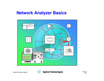
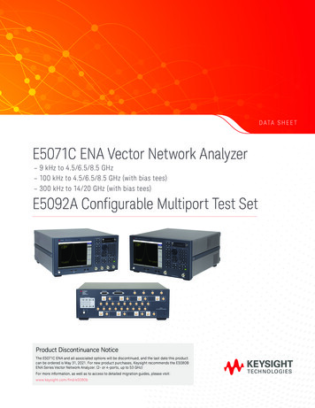
1HP 87533 Front and Rear PanelFront Panel FeaturesCautionDo not mistake the line switch for the disk ejectbutton. See the figure below. If the line switch ismistakenly pushed, the instrument will be turned off,losing all settings and data that have not been saved.Figure l-l. HP 87533 Front PanelFigure l-l shows the location of the following front panel features andkey function blocks. These features are described in more detail later inthis chapter.1.LINE switch. This switch controls ac power to the analyzer. 1 ison, 0 is off.HP 87533 Front and Rear Panell-l
2.Display. This shows the measurement data traces, measurementannotation, and softkey labels. The display is divided into specificinformation areas, illustrated in Figure l-2.3.Disk drive. This 3.5 inch drive allows you to store and recallinstrument states and measurement results for later analysis.4.Disk eject button.5.Softkeys. These keys provide access to menus that are shown onthe display.6.STlMULUS function block. The keys in this block allow you tocontrol the analyzer source’s frequency, power, and other stimulusfunctions.7.RJZSPONSE function block. The keys in this block allow youto control the measurement and display functions of the activedisplay channel.8.ACTIVE CHANNEL keys. These keys activate one of the fourmeasurement channels. Once activated, a channel can then beconfigured for making measurements.The analyzer has four display channels. (-1) activates channel1 or 3, and (Chanj activates channel 2 or 4. Refer to “UsingDisplay Functions” in Chapter 2 for information on enablingchannels 3 and 4 and making them active.9.The ENTRY block. This block includes the knob, the step @) @keys, and the number pad. These allow you to enter numericaldata and control the markers.You can use the numeric keypad to select digits, decimal points,and a minus sign for numerical entries. You must also select a unitsterminator to complete value inputs.The backspace key @ has two independent functions:H Modifies entries and test sequences.nTurns off the softkey menu and, if more than one marker isactive, the marker information is displayed in the softkey area.Refer to “Markers and the Backspace Key” in Chapter 2.1-2HP 87533 Front and Rear Panel
10.INSTRUMENT STATE function block. These keys allow youto control channel-independent system functions such as thefollowing:w copying, save/recall, and HP-R3 controller modew limit testingnexternal source modentuned receiver modenfrequency offset modentest sequence functionnharmonic measurements (Option 002)ntime domain transform (Option 010)HP-R3 STATUS indicators are also included in this block.11.IPreseT) key. This key returns the instrument to either a knownfactory preset state, or a user preset state that can be deEned.Refer to the “Preset State and Memory Allocation” chapter for acomplete listing of the instrument preset condition.12.PROBE POWER connector. This connector (fused inside theinstrument) supplies power to an active probe for in-circuitmeasurements of ac circuits.13.R CX4NNEL connectors. These connectors allow you to apply aninput signal to the analyzer’s R channel, for frequency offset mode.14.PORT 1 and PORT 2. These ports output a signal from the sourceand receive input signals from a device under test. PORT 1 allowsyou to measure SIZ and ‘&I. PORT 2 allows you to measure Saland S22.HP 87533 Front and Rear Panell-3
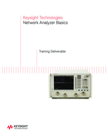
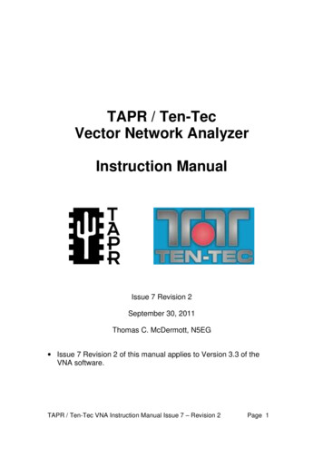
Analyzer DisplayP14/@d12bPWdFigure l-2. Analyzer Display (Single Channel, Cartesian Format)The analyzer display shows various measurement information:w The grid where the analyzer plots the measurement data.The currently selected measurement parameters.nw The measurement data traces.Figure l-2 illustrates the locations of the different information labelsdescribed below. In addition to the single-channel display shown inFigure l-2, multiple graticule and channel displays are available, asdescribed in “Using Display Functions” in Chapter 2.When multiple channels are superimposed or displayed in separategraticules, information is arranged as follows:nnnChannel(s) displayed and measurement parameter(s) are at the top ofeach graticule.Stimulus frequency information is at the bottom of each graticule.Marker information (when selected) is on the right side of eachgraticule.l-4HP 87633 Front and Rear Panel
1.Stimulus Start Value. This value could be any one of thefollowing:lThe start frequency of the source in frequency domainmeasurements.m The start time in CW mode (0 seconds) or time domainmeasurements.nThe lower power value in power sweep.When the stimulus is in center/span mode, the center stimulusvalue is shown in this space.2.Stimulus Stop Value. This value could be any one of thefollowing:m The stop frequency of the source in frequency domainmeasurements.mlThe stop time in time domain measurements or CW sweeps.The upper limit of a power sweep.When the stimulus is in center/span mode, the span is shown inthis space. The stimulus values can be blanked.(For CW time and power sweep measurements, the CW frequencyis displayed centered between the start and stop times or powervalues.)3.Status Notations. This area shows the current status of variousfunctions for the active channel.The following notations are used:Avg Sweep-to-sweep averaging is on. The averaging count isshown immediately below.Cor Error correction is on. (For error-correction procedures,refer to Chapter 5,
Title: HP 8753E Network Analyzer Quick Reference Guide Author: Tim