Transcription
Network AnalyzeryBasicsNetwork Analyzer BasicsCopyright2000
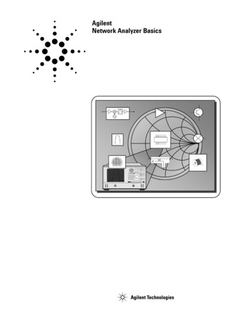
Network Analysis is NOT. RouterBridgeRepeaterHubYour IEEE 802.3 X.25 ISDNswitched-packet data streamis running at 147 MBPS with-9a BER of 1.523 X 10 . . .Network Analyzer BasicsCopyright2000
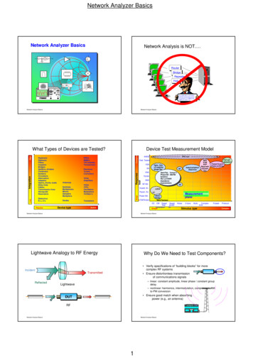
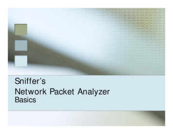
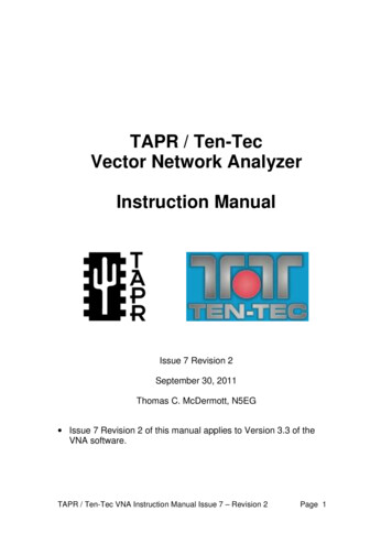
LowIntegrationHighWhat Typesyp of Devices are itters, aptersOpens, shorts, loadsD l liDelaylinesCablesTransmission linesWaveguideResonatorsDielectricsR, L, C'sPassiveNetwork Analyzer BasicsRFICsMMICsT/R modulesTransceiversReceiversTunersCon iplexersMixersSamplersM lti liMultipliersDiodesDevice nsistorsActiveCopyright2000
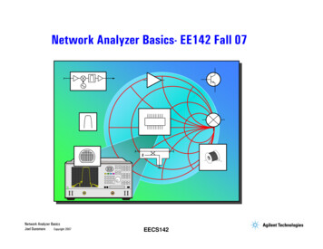
LightwavegAnalogygy to RF Network Analyzer BasicsCopyright2000
Whyy Do We Need to Test Components?p Verify specifications of “buildingbuilding blocksblocks” for morecomplex RF systems Ensure distortionless transmissionof communications signals– linear: constant amplitude, linear phase / constant groupdelay– nonlinear: harmonicsharmonics, intermodulationintermodulation, compressioncompression, AMAMto-PM conversion Ensure good match when absorbingpower (e.g.,(e g an antenna)KPWRNetwork Analyzer BasicsFM 97Copyright2000
The Need for Both Magnitudegand PhaseS211. Completecharacterizationht i ti offlinear networksS11S22S122. Complex impedanceneededd d tto ddesignimatching circuits4. Time-domaincharacterizationht i tiMag3 C3.Complexl valueslneeded for devicemodelingHigh-frequency transistor modelTime5. Vector-error correctionErrorBaseCollectorEmitterNetwork Analyzer BasicsMeasuredActualCopyright2000
Agendag Network Analyzer BasicsWhat measurements do we make? Transmission-line basics Reflection and transmissionparameters S-parameter definitionNetwork analyzer hardware Signal separation devices Detection types Dynamic range T/R versus S-parameterS parameter test setsError models and calibration Types of measurement error One- and two-port models ErrorError-correctioncorrection choices Basic uncertainty calculationsExample measurementsAppendixCopyright2000
Transmission Line Basics I-Low frequencies wavelengths wire length current (I) travels down wires easily for efficient powertransmission measured voltage and current not dependent on position alongwireHigh frequencies wavelength or length of transmission medium need transmission lines for efficient power transmission matching to characteristic impedance (Zo) is very importantfor low reflection and maximum power transfer measured envelope voltage dependent on position alonglineNetwork Analyzer BasicsCopyright2000
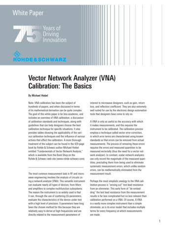
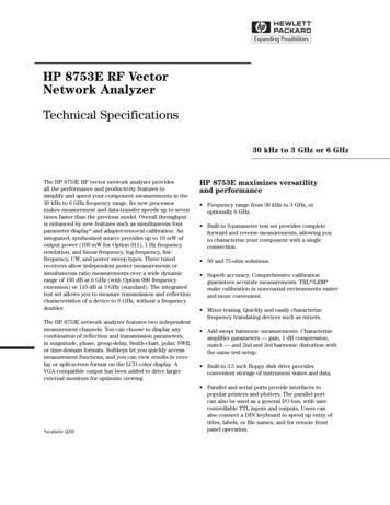
Transmission line Zo Zo determines relationship between voltage and currentwavesZo is a function of physical dimensions and rZo is usually a real impedance (e.g. 50 or 75 ohms)1.5Twisted-pairattenuation islowest at 77 ohms1.4Waveguide1.3a1.2b rCoaxialhnormalized vallues 111.11.00.90.8h0.7w1w2CoplanarNetwork Analyzer Basics50 ohm standardpower handling capacitypeaks at 30 ohms0.6w0.510Microstrip2030405060 70 80 90 100characteristic impedancefor coaxial airlines (ohms)Copyright2000
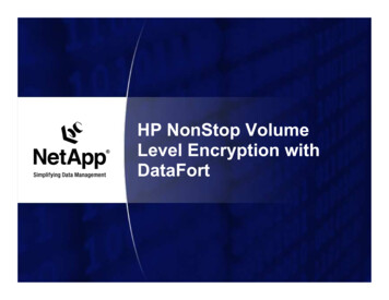
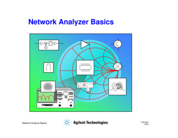
Power Transfer EfficiencyyRSFor complex impedances, maximumpower transfer occurs when ZL ZS*(conjugate match)RLRsLoad Power(normalized)1.2 jX1-jX0.80.606RL0.40.20012345678910RL / RSMaximum power is transferred when RL RSNetwork Analyzer BasicsCopyright2000
Transmission Line Terminated with ZoZs ZoZo characteristicimpedance of transmissionlineZoV incVrefl 0! (all the incident poweris absorbed in the load)For reflection, a transmission line terminated in Zobehaves like an infinitely long transmission lineCopyright 2000Network Analyzer Basics
Transmission Line Terminated with Short, OpenZs ZoV incVreflIn phase (0o) for openIn-phaseopen,out-of-phase (180o) for shortFor reflection, a transmission line terminated ina short or open reflects all power back tosourceCopyright 2000Network Analyzer Basics
Transmission Line Terminated with 25 Zs ZoZL 25 V incVreflStanding wave pattern doesnot go to zero as with short oropenCopyright 2000Network Analyzer Basics
High-Frequencygqy Device NSMISSIONREFLECTIONReflectedIncident SWRS-ParametersS11, S22ReflectionCoefficient Network Analyzer ittanceR jX,RjX,G jB BRGroupGropDelayGain / LossS-ParametersS21, S12TransmissionC ffCoefficient InsertionPhaseCopyright2000
Reflection ParametersReflectionCoefficient Vreflected VincidentReturn loss -20 log( ), ZL ZOZ L ZO EmaxEminVoltage Standing WaveRatioEmaxVSWR Emin 1 1- Full reflection(ZL open, short)No reflection(ZL Zo)0 1 dBRL0 dB1VSWR Network Analyzer BasicsCopyright2000
Smith Chart Review. jXPolar plane90o1.0.88.60 R.4 180 o-o.20 -jX-90 oRectilinear impedanceplaneConstant XConstant RZ L ZoSmith Chart mapsrectilinearimpedanceplane onto polarplanelNetwork Analyzer Basics 0 1(open)ZL Z L 0 (short) 1O 1800Smith chartCopyright2000O
Transmission ParametersV IncidentVTransmittedDUTV Transmission Coefficient Transmitted VVInsertion Loss (dB) - 20 LogVNetwork Analyzer BasicsTTrans IncTransGain (dB) 20 Log 20 logVIncident - 20 logV IncCopyright2000
Linear Versus Nonlinear BehaviorA * Sin 360o * f (t - to)ALinear behavior: TimetoSin 360o * f * tATimef1DUTInput phase shift to * 360o * fiinputt andd outputt t frequenciesfi arethe same (no additionalfrequencies created)output frequency only undergoesmagnitude and phase changeFrequencyOutputNonlinear behavior:f1 FrequencyTime fNetwork Analyzer Basics1Frequencyoutput frequency mayundergo frequency shift(e.g. with mixers)additional frequenciescreated (harmonics,i tintermodulation)d l ti )Copyright2000
Criteria for Distortionless TransmissionLinear NetworksLinear phase overbandwidth ofinterestMagnnitudeConstant amplitude overbandwidth of interestPhaseFrequencyFrequencyNetwork Analyzer BasicsCopyright2000
Magnitude Variation with FrequencyF(t)( ) sin wt 1/3 sin 3wt 1/5 sin 5wtTimeTimeMagnituudeLinearNetworkFrequencyNetwork Analyzer BasicsFrequencyFrequencyqyCopyright2000
Phase Variation with FrequencyF(t) sin wt 1 /3 sin 3wt 1 /5 sin 5wtLinear NetworkTimeMagnitudeTimeFrequency0 Frequency-180 Frequency-360360 Network Analyzer BasicsCopyright2000
Deviation from Linear PhaseUse electrical delay toremove linear portion ofphase responseLinear electrical lengthaddedPhasse 45 /DivRF filter responseDeviation from linearphasepooPhasee 1 /Div(Electrical delay function) FrequencyLow resolutionNetwork Analyzer BasicsyieldsyFrequencyFrequencyHigh resolutionCopyright2000
Groupp DelayyFrequency tgGroup delay ripple to PhaseAverage delay FrequencyGroup Delay (tg) d d 1360 o*d dfin radiansin radians/sec group-delay ripple indicates phase distortionaverage delay indicates electrical length of DUTaperture of measurement is very importantin degreesf in Hertz (( f))Network Analyzer BasicsCopyright2000
PhassePhasseWhyy Measure Groupp Delay?yff d d GroupDelayGroupDelay d d ffSame pp-pp phase ripple can resultres lt in differentgroup delayNetwork Analyzer BasicsCopyright2000
Characterizingg Unknown DevicesUsing parameters (H, Y, Z, S) to characterize devices: gives linear behavioral model of our devicemeasure parameters (e.g.(e g voltage and current) versus frequencyundervarious source and load conditions (e.g. short and opencircuits)compute device parameters from measured datapredict circuit performance under any source and load conditionsH-parametersV1 h11I1 h12V2I2 h21I1 h22V2Y-parametersI1 y11V1 y12V2I2 y21V1 y22V2Z-parametersV1 z11I1 z12I2V2 z21I1 z22I2h11 V1I1V2 0(requires short circuit)h12 V1V2I1 0(requires open circuit)Copyright 2000Network Analyzer Basics
Why Use SS-Parameters?Parameters? relatively easy to obtain at high frequencies measure voltage traveling waves with a vector network analyzer don't need shorts/opens which can cause active devices to oscillate or self-destructrelate to familiar measurements (gain, loss, reflection coefficient .)can cascade S-parameters of multiple devices to predict system performancecan compute H,H YY, or Z parameters from S-parametersS parameters if desiredcan easily import and use S-parameter files in our electronic-simulation toolsS 21IncidentTransmitteda1b2S 11ReflectedDUTb1S 22ReflectedPort 2P t1Porta2TransmittedS 12Incidentb 1 S 11 a 1 S 12 a 2b 2 S 21 a 1 S 22 a 2Copyright 2000Network Analyzer Basics
Measuringg S-Parametersa1ForwardS 21 b1Incidenta2 0b1 a1ba2 0Z0a2 0DUTLoadNetwork Analyzer BasicsS 22 2 a1a1 0b1LoadDUTReflectedTransmittedb2Transmitted21Z0S 11ReflectedRfl t dIncidentS 11 SIncidentTTransmitteditt dS 12S 12 ReflectedIncidentTransmittedIncidentS 22b2 a2ba1 01 a2a1 0b2ReverseReflecteda2I id tIncidentCopyright2000
Equating S-Parameters with Common Measurement TermsS11 fforwardd reflectionfl ti coefficientffi i t (input(it match)t h)S22 reverse reflection coefficient (output match)S21 forward transmission coefficient (gain or loss)S12 reverseSe e se ttransmissiona s ss o coecoefficientc e t ((isolation)so at o )Remember, S-parameters are inherentlycomplex, linear quantities -- however, we oftenexpress them in a loglog-magnitudemagnitude formatCopyright 2000Network Analyzer Basics
Criteria for Distortionless TransmissionNonlinear Networks Saturation, crossover, intermodulation, andother nonlinear effects can cause signaldistortionEffect on system depends on amount and typeof distortion and system architectureTimeFrequencyNetwork Analyzer BasicsTimeFrequencyCopyright2000
Measuringg Nonlinear BehaviorMost common measurements: using a network analyzer and power sweeps gain compression AM to PM conversioni using a spectrum analyzer source(s) harmonics, particularly second and third intermodulation products resultingfromttwoor more RF carriersiRL 0 dBm8563ALPFLPFNetwork Analyzer BasicsSPECTRUM ANALYZERATTEN10 dB10 dB / DIV9 kHz - 26.5 GHzDUTCENTER 20.00000 MHzRB 30 HzVB 30 HzSPAN 10.00 kHzST 20 secCopyright2000
What is the DifferenceBetween Network andSpectrum e Ratio8563A measure components, devices,circuits, sub-assembliescontain source and receiverdisplay ratioed amplitude and phase(frequency or power sweeps)offer advanced error correctionFrequencySpectrum analyzers: measure signal amplitude characteristicscarrier level, sidebands, harmonics.)can demodulate (& measure) complex signalsare receivers only (single channel)can be used for scalar component test (nophase) with tracking gen. or ext. source(s)Copyright 2000Network Analyzer Basics9 kHz - 26.5MeasuresunknownsignalsFrequencyNetwork analyzers:SPECTRUM ANALYZERGHz
Agendag Network Analyzer BasicsWhat measurements do we make?Network analyzer hardwareError models and calibrationExample measurementsAppendixCopyright2000
Generalized Network AnalyzeryBlock EIVER / DETECTORPROCESSOR / DISPLAYNetwork Analyzer BasicsCopyright2000
Source Suppliesppstimulus for systemySwept frequency or powerTraditionally NAs used separatesourceMost Agilent analyzers soldtoday have integrated,synthesized sourcesNetwork Analyzer BasicsCopyright2000
OURCESIGNALSEPARATIONINCIDENT (R)REFLECTED(A)TRANSMITTED(B)RECEIVER / DETECTORPROCESSOR / DISPLAY measure incident signal for referenceseparate incident and reflected signalssplitterbridgedirectionalcouplerNetwork Analyzer BasicsDetectorTest PortCopyright2000
DirectivityyDirectivity is a measure of how well acoupler can separate signals movingin opposite directions((undesiredd i d leakagel ksignal)(desired(di d reflectedfl t dsignal)Test portDirectional CouplerNetwork Analyzer BasicsCopyright2000
Interaction of Directivityy with theDUT (Without Error Correction)0DevicceReturn LoossDirecttivityData MaxDUT RL 40 dB30Add in-phase60Network Analyzer BasicsDeviceDDeviceeDirectivityFrequencyData MinAdd out-of-phase(cancellation)Data Vector SumDirectivityCopyright2000
IncidentDetector TypesypTransmittedDUTReflectedSOURCEDiodeScalar broadband(no phasei finformation)ti )SIGNALSEPARATIONINCIDENT (R)REFLECTED(A)TRANSMITTED(B)RECEIVER / DETECTORPROCESSOR / DISPLAYDCRFACTuned ReceiverIF F LO F RFRFADC / DSPVector(magnitude andphase)IF FilterLONetwork Analyzer BasicsCopyright2000
Broadband Diode Detection 10 MHzNetwork Analyzer BasicsEasy to make broadbandInexpensive compared to tuned receiverGood for measuring frequency-translating devicesImprove dynamic range by increasing powerMedium sensitivity / dynamic range26.5 GHzCopyright2000
Narrowband Detection - Tuned ReceiverADC / DSP 10 MHzNetwork Analyzer BasicsBest sensitivity / dynamic rangeProvides harmonic / spurious signal rejectionImprove dynamic range by increasing power,decreasing IF bandwidth, or averagingTrade off noise floor and measurement speed26.5 GHzCopyright2000
Comparisonpof Receiver TechniquesqBroadband(diode)(dode) detectiondetect o0 dBNarrowband(tuned-receiver)(tued ece e )detection0 dB-50 dB-50 dB-100 dB-100 dB-60 dBm Sensitivity higher noise floorfalse responses -100 dBm Sensitivity high dynamic rangeharmonic immunityDynamic range maximum receiver power - receiver noisefloorNetwork Analyzer BasicsCopyright2000
DynamicyRangeg and AccuracyyError Due to Interfering Signal100-Erroor (dB, deg)10 Dynamic rangeis very importantfor measurementaccuracy!!phase error1magng -60-65-70Interfering signal (dB)Network Analyzer BasicsCopyright2000
T/R Versus S-Parameter Test SetsS-Parameter Test SetTransmission/Reflection Test SetSourceSourceTransfer switchRBAPort 1 Port 2Port 1FwdDUTRF always comes out port 1port 2 is always receiverresponse, one-port cal availableNetwork Analyzer BasicsBAPort 2Fwd R DUTRevRF comes out port 1 or port 2forward and reverse measurementstwo-port calibration possibleCopyright2000
Processor / Displayp yIncidentTransmittedDUT50 MH-20GHzNETWORK MITTED(B)HP-IB STATUSPORT 1PORT 2RECEIVER / DETECTORPROCESSOR / DISPLAYmarkers limit lines pass/fail indicators linear/log formats grid/polar/Smithcharts Network Analyzer BasicsR CHANNELINSTRUMENTSTATECopyright2000R LS
SpectrumpAnalyzery/ Trackingg GeneratorRF inIF8563ASPECTRUM ANALYZER9 kHz - 26.5 GHzLODUTSpectrum analyzerTG outf IFDUTT ki generatorTrackingtKey differences from network analyzer: one channel -- no ratioed or phase measurementsMore expensive than scalar NA (but better dynamic range)Only error correction available is normalization (and possibly open-short averaging)Poorer accuracySmall incremental cost if SA is required for other measurementsNetwork Analyzer BasicsCopyright2000
Agendag What measurements do wemake?Network analyzer hardwareError models and calibrationExample measurementsAppendixWhy do we even need error-correction andcalibration? It is impossible to make perfect hardware It would be extremely expensive to make hardwaregood enough to eliminate the need for error correctionNetwork Analyzer BasicsCopyright2000
Calibration Topicsp Network Analyzer BasicsWhat measurements do we make?Network analyzer hardwareError models and calibration measurement errors what is vector error correction? calibration types accuracy examples calibration considerationsExample measurementsAppendixCopyright2000
Measurement Error ModelinggSystematic errors due to imperfections in the analyzer and test setup assumed to be time invariant (predictable)Random errors vary with time in random fashion (unpredictable) main contributors: instrument noise, switch and connector repeatabilityDrift errors due to system performance changing after a calibration has been done primarily caused by temperature nDeviceDRIFTNetwork Analyzer BasicsCopyright2000
SystematicyMeasurement ErrorsRDirectivityABCCrosstalklkDUTFrequency response reflection tracking (A/R) transmission tracking (B/R)SourceMismatchLoadMismatchSix forward and six reverse error termsyields 12 error terms for two-portypdevicesNetwork Analyzer BasicsCopyright2000
Typesyp of Error Correction response (normalization)simple to performonly corrects for tracking errorsstores reference trace in memory,thruthen does data divided by memoryvectorrequires more standardsrequires an analyzer that can measure phaseaccounts for all major sources of systematic error SHORTS11aS11 mNetwork Analyzer BasicsthruOPENLOADCopyright2000
What is Vector-Error Correction? Process of characterizing systematic error termsmeasure known standardsremove effects from subsequent measurements1-port calibration (reflection measurements)onlyy 3 systematicyerror terms measureddirectivity, source match, and reflection trackingFull 2-port calibration (reflection and transmission measurements)12 systematic error terms measuredusuallyy requiresq12 measurements on four known standards ((SOLT))Standards defined in cal kit definition filenetwork analyzer contains standard cal kit definitionsCAL KIT DEFINITION MUST MATCH ACTUAL CAL KIT USED!User-built standards must be characterized and entered into usercal-kit Copyright 2000Network Analyzer Basics
Reflection: One-Port ModelError AdapterIdealRF inRF in1ED DirectivityS11AESEDS11AERT Reflection trackingES Source MatchS11MS11MS11M MeasuredERTS11A ActualTo solve for error terms, wemeasure 3 standards togenerate 3 equations and 3unknowns S11AS11M ED ERT1 - ES S11AAssumes good termination at port two if testing two-port devicesIf using port 2 of NA and DUT reverse isolation is low (e.g., filter passband):assumption of good termination is not validtwo-portp error correction yyields better results Network Analyzer BasicsCopyright2000
Before and After One-Port Calibration02.0data before 1-portcalibration111.1VSWRVReturrn Loss (dBB)20401.01data after 1-portcalibrationlib ti601.0016000Network Analyzer BasicsMHMHz12000Copyright2000
Two-Port Error CorrectionReverse modelForward modelPort 1Port 2E RT'EXPort 1Port 2S21a1a1EDS21AESS11Ab1E RTS22ETTAELb2S 12E D' rev directivityE SS' rev source matchE RT' rev reflection trackingEL' rev load matchETTTT' rev transmission trackingEX' rev isolation S22AE S'ED'E TT'S12 AEX'AEL fwd load matchETT fwd transmission trackingEX fwd isolation S11Ab1b2Aa2ED fwd directivityE S fwd source matchERT fwd reflection tracking E L'Each actual S-parameter is a functionof all four measured S-parametersA lAnalyzermustt makek forwardfd anddreverse sweep to update any one SparameterLuckily, you don't need to know theseequationsqto use network analyzers!!!yNetwork Analyzer BasicsCopyright2000a2
Crosstalk: Signal Leakage Between Test Ports During Transmission Can be a problem with:high-isolation devices (e.g., switch in open position)high-dynamic range devices (some filter stopbands)Isolation calibrationadds noise to error model (measuring near noise floor ofsystem)only perform if really needed (use averaging if necessary)if crosstalk is independent of DUT match, use twoterminationsif dependent on DUT match, use DUT with termination onoutputDUT LOADNetwork Analyzer BasicsDUTDUTLOADCopyright2000
Errors and Calibration StandardsUNCORRECTEDFULL 2-PORTRESPONSE1-PORTSHORTDUTOPENthruConvenient Generally notaccurate No errors removedLOAD SHORTSHORTOPENOPENLOADLOADDUTEasy to perform Use when highestaccuracy isi not
Title: Microsoft PowerPoint - Network analyzer.ppt [Compatibilit