Transcription
Improving Network AnalyzerMeasurements ofFrequency-translating DevicesApplication Note 1287-7LORFLO-RFLO RFIFRFLOIFIFLORFLO-RFLO RFIFRFLOIFIFLORFLO-RFLO RFIFRFLOIFLORFLO-RFLO RFIFRFLOIFIFIF
Table of ContentsPageIntroduction . . . . . . . . . . . . . . . . . . . . . . . . . . . . . . . . . . . . . . . . . . . . . . . . . . . . . . . . . . . . . . . . . . . . . . 3Network Analyzer Mixer Measurement Configurations . . . . . . . . . . . . . . . . . . . . . . . . . . . . . . . . . 3Scalar Network Analyzer Configuration . . . . . . . . . . . . . . . . . . . . . . . . . . . . . . . . . . . . . . . . . . . . . . . . . . . . . . . . . . 4Vector Network Analyzer in Frequency Offset Mode Configuration . . . . . . . . . . . . . . . . . . . . . . . . . . . . . . . . . . . . . 5The Upconversion/Downconversion Technique . . . . . . . . . . . . . . . . . . . . . . . . . . . . . . . . . . . . . . . . . . . . . . . . . . . . 5Conversion Loss . . . . . . . . . . . . . . . . . . . . . . . . . . . . . . . . . . . . . . . . . . . . . . . . . . . . . . . . . . . . . . . . . . 6Definition and Importance of Conversion Loss . . . . . . . . . . . . . . . . . . . . . . . . . . . . . . . . . . . . . . . . . . . . . . . . . . . . .Measurement Considerations . . . . . . . . . . . . . . . . . . . . . . . . . . . . . . . . . . . . . . . . . . . . . . . . . . . . . . . . . . . . . . . . . .Mismatch Errors . . . . . . . . . . . . . . . . . . . . . . . . . . . . . . . . . . . . . . . . . . . . . . . . . . . . . . . . . . . . . . . . . . . . . . . . . .Considerations Unique to the Scalar Network Analyzer . . . . . . . . . . . . . . . . . . . . . . . . . . . . . . . . . . . . . . . . . . . .Importance of Proper Filtering . . . . . . . . . . . . . . . . . . . . . . . . . . . . . . . . . . . . . . . . . . . . . . . . . . . . . . . . . . . . . .Frequency Response Error . . . . . . . . . . . . . . . . . . . . . . . . . . . . . . . . . . . . . . . . . . . . . . . . . . . . . . . . . . . . . . . . .Considerations Unique to the Vector Network Analyzer . . . . . . . . . . . . . . . . . . . . . . . . . . . . . . . . . . . . . . . . . . .Importance of Proper Filtering . . . . . . . . . . . . . . . . . . . . . . . . . . . . . . . . . . . . . . . . . . . . . . . . . . . . . . . . . . . . .Sampling Architecture and Issues . . . . . . . . . . . . . . . . . . . . . . . . . . . . . . . . . . . . . . . . . . . . . . . . . . . . . . . . . .R-Channel Phase-Locking Considerations . . . . . . . . . . . . . . . . . . . . . . . . . . . . . . . . . . . . . . . . . . . . . . . . . . . .LO Accuracy and Stability . . . . . . . . . . . . . . . . . . . . . . . . . . . . . . . . . . . . . . . . . . . . . . . . . . . . . . . . . . . . . . . .Power-Meter Calibration . . . . . . . . . . . . . . . . . . . . . . . . . . . . . . . . . . . . . . . . . . . . . . . . . . . . . . . . . . . . . . . . . .Accuracy Comparison of the 8757D and a Vector Network Analyzer . . . . . . . . . . . . . . . . . . . . . . . . . . . . . . . . . . .Fixed IF Measurements . . . . . . . . . . . . . . . . . . . . . . . . . . . . . . . . . . . . . . . . . . . . . . . . . . . . . . . . . . . . . . . . . . . . .6779991010101212131617Relative Phase Measurements . . . . . . . . . . . . . . . . . . . . . . . . . . . . . . . . . . . . . . . . . . . . . . . . . . . . . 18Relative Phase and Magnitude Tracking . . . . . . . . . . . . . . . . . . . . . . . . . . . . . . . . . . . . . . . . . . . . . . . . . . . . . . . . .Group Delay . . . . . . . . . . . . . . . . . . . . . . . . . . . . . . . . . . . . . . . . . . . . . . . . . . . . . . . . . . . . . . . . . . . . . . . . . . . . . .Important Parameters when Specifying Group Delay . . . . . . . . . . . . . . . . . . . . . . . . . . . . . . . . . . . . . . . . . . . . .Absolute Group Delay . . . . . . . . . . . . . . . . . . . . . . . . . . . . . . . . . . . . . . . . . . . . . . . . . . . . . . . . . . . . . . . . . . . . .Upconversion/downconversion . . . . . . . . . . . . . . . . . . . . . . . . . . . . . . . . . . . . . . . . . . . . . . . . . . . . . . . . . . . . . .Modulation delay . . . . . . . . . . . . . . . . . . . . . . . . . . . . . . . . . . . . . . . . . . . . . . . . . . . . . . . . . . . . . . . . . . . . . . . . .Time domain . . . . . . . . . . . . . . . . . . . . . . . . . . . . . . . . . . . . . . . . . . . . . . . . . . . . . . . . . . . . . . . . . . . . . . . . . . . .Measuring delay linearity . . . . . . . . . . . . . . . . . . . . . . . . . . . . . . . . . . . . . . . . . . . . . . . . . . . . . . . . . . . . . . . . . . .1819192020202123Reflection Measurements . . . . . . . . . . . . . . . . . . . . . . . . . . . . . . . . . . . . . . . . . . . . . . . . . . . . . . . . . 24Isolation Measurements . . . . . . . . . . . . . . . . . . . . . . . . . . . . . . . . . . . . . . . . . . . . . . . . . . . . . . . . . . 25Feedthrough Measurement of Converters and Tuners . . . . . . . . . . . . . . . . . . . . . . . . . . . . . . . . . . . . . . . . . . . . . . 26Absolute Group Delay — A More Accurate, Lower Ripple Technique . . . . . . . . . . . . . . . . . . . . 27Measurement Configuration Using the Mixer Pair . . . . . . . . . . . . . . . . . . . . . . . . . . . . . . . . . . . . . . . . . . . . . . . . .Labeling Conventions . . . . . . . . . . . . . . . . . . . . . . . . . . . . . . . . . . . . . . . . . . . . . . . . . . . . . . . . . . . . . . . . . . . . . .Proper Filtering . . . . . . . . . . . . . . . . . . . . . . . . . . . . . . . . . . . . . . . . . . . . . . . . . . . . . . . . . . . . . . . . . . . . . . . . . .LO Effects . . . . . . . . . . . . . . . . . . . . . . . . . . . . . . . . . . . . . . . . . . . . . . . . . . . . . . . . . . . . . . . . . . . . . . . . . . . . . .System Calibration and Test . . . . . . . . . . . . . . . . . . . . . . . . . . . . . . . . . . . . . . . . . . . . . . . . . . . . . . . . . . . . . . . .Calibrating the Test System with the Calibration Mixer . . . . . . . . . . . . . . . . . . . . . . . . . . . . . . . . . . . . . . . . . . . . .Calibration Configuration . . . . . . . . . . . . . . . . . . . . . . . . . . . . . . . . . . . . . . . . . . . . . . . . . . . . . . . . . . . . . . . . . . .Calibration Error Terms and Equations . . . . . . . . . . . . . . . . . . . . . . . . . . . . . . . . . . . . . . . . . . . . . . . . . . . . . . . .Test Procedure for Calibrating the Test System . . . . . . . . . . . . . . . . . . . . . . . . . . . . . . . . . . . . . . . . . . . . . . . . .First-Order Error Correction: Frequency Response . . . . . . . . . . . . . . . . . . . . . . . . . . . . . . . . . . . . . . . . . . . . .Second-Order Error Correction: Frequency Response and Input Match . . . . . . . . . . . . . . . . . . . . . . . . . . . . .Third-Order Error Correction: Frequency Response, Input and Output Match . . . . . . . . . . . . . . . . . . . . . . . .282829292929293031313233Appendix A . . . . . . . . . . . . . . . . . . . . . . . . . . . . . . . . . . . . . . . . . . . . . . . . . . . . . . . . . . . . . . . . . . . . . 34Calibration mixer attitudes . . . . . . . . . . . . . . . . . . . . . . . . . . . . . . . . . . . . . . . . . . . . . . . . . . . . . . . . . . . . . . . . . . . 34Appendix B . . . . . . . . . . . . . . . . . . . . . . . . . . . . . . . . . . . . . . . . . . . . . . . . . . . . . . . . . . . . . . . . . . . . . 35Program for Fixed IF Measurements with One External LO Source . . . . . . . . . . . . . . . . . . . . . . . . . . . . . . . . . . . 35Appendix C . . . . . . . . . . . . . . . . . . . . . . . . . . . . . . . . . . . . . . . . . . . . . . . . . . . . . . . . . . . . . . . . . . . . . . 37Uncertainty in Mixer Group Delay Measurements . . . . . . . . . . . . . . . . . . . . . . . . . . . . . . . . . . . . . . . . . . . . . . . . . 37Appendix D . . . . . . . . . . . . . . . . . . . . . . . . . . . . . . . . . . . . . . . . . . . . . . . . . . . . . . . . . . . . . . . . . . . . . 39Related Application and Product Notes/Other Suggested Reading/Third Party Companies . . . . . . . . . . . . . . . . . 392
IntroductionFrequency-translation devices (FTDs)such as mixers, converters, and tunersare critical components in most RFand microwave communicationsystems. As communication systemsadopt more advanced types ofmodulation, FTD designs are increasingly complex, tests are morestringent with tighter specifications,and the need to reduce costs is moreimportant than ever.The measurement trade-offs forfrequency-translating devices varywidely among different industries.Measurement accuracy, speed, costand ease of setup are among theconsiderations for determining thebest test equipment. This applicationnote explores current test equipmentsolutions and techniques that can beused to accurately characterize andtest frequency-translating devices.Frequency-translating devices presentunique measurement challenges sincetheir input and output frequenciesdiffer. These require differentmeasurement techniques than thoseused for a linear device such as afilter. This note covers linearfrequecy-translation measurements,such as magnitude, relative phase,reflection and isolation. Correspondingaccuracy issues are also discussed.Network analyzer mixermeasurement configurationsNetwork analyzers used for testingfrequency-translation devices includescalar network analyzers, vectornetwork analyzers with frequencyoffset capability, and vector networkanalyzers using an upconversion/downconversion configuration. Eachsolution has its own advantages anddisadvantages. This section provides asynopsis of the three configurations soyou can quickly evaluate which is thebest fit for your measurement needs.Detailed information about eachsolution is discussed in later sections.To get the most from this note, youshould have a basic under-standing offrequency translation terminology,such as “RF port,” “IF port” and “LOport.” Understanding of fundamentalRF and network analyzer terms suchas S-parameters, VSWR, group delay,match, port, full two-port calibration,and test set is also expected. For abetter understanding of such terms, alist of reference material appear in theAppendix section.3
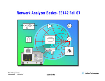
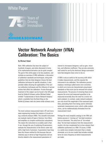
Scalar network analyzerconfigurationThe most economical instrument forFTD tests is a scalar network analyzer.A scalar network analyzer uses diodedetectors that can detect a very wideband of frequencies. This capabilityenables a scalar network analyzerto detect signals when the receiverfrequency is different from the sourcefrequency. Magnitude-only measurements such as conversion loss,absolute output power, return loss andisolation can be made, as well asnonlinear magnitude measurementssuch as gain compression. Group delayinformation is available in some scalarnetwork analyzers using an AM-delaytechnique, which employs amplitudemodulation.AM-delay measurements are lessaccurate than group delay measurements obtained with a vector networkanalyzer. AM delay typically has anuncertainty of around 10 to 20 ns,whereas group delay with a vectornetwork analyzer has an uncertaintyas good as 150 ps. Advantages of thescalar solution include low cost andgood magnitude accuracy. As shown inFigure 1, fully integrated scalarnetwork analyzers such as the 8711Cor 8713C provide economical RFmeasurements up to 3 GHz, andinclude AM delay capability. The8757D scalar network analyzer, shownin Figure 2, measures up to 110 GHz,and provides very good absolutepower measurements, particularlywhen installed with an internal powercalibrator and used with precisiondetectors. In certain cases, such asmeasuring FTDs with an internal filter,the 8757D with internal powercalibrator and precision detector cantypically make more accurate magnitude measurements than a vectornetwork analyzer.8711CRF network analyzerExternal LO source10 dBLowpass filter10 dBFigure 1. 8711C scalar network analyzer configuration8757Dscalar network analyzerSweeperDirectional bridgeExternal LO sourceLowpass filterPrecision detectorFigure 2. 8757D scalar network analyzer configuration4
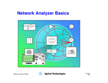
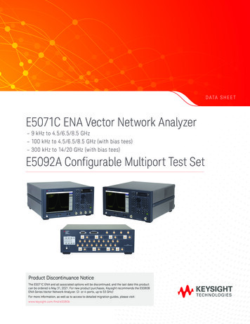
Vector network analyzer in frequencyoffset mode configurationThe upconversion/downconversion techniqueA more versatile solution for FTD testis a vector network analyzer. A vectornetwork analyzer uses a tuned-receiver narrowband detector, which allowsmeasurements of both magnitude andrelative phase. The vector networkanalyzer’s frequency offset mode offsets the analyzer’s receiver from it’ssource by a given LO frequency, andmakes frequency-translation measurements possible.A vector network analyzer in normaloperating mode can also be configuredfor frequency-translation measurements. This configuration has twomain advantages. First, the instrumentcan be used to measure a FTD’smagnitude and relative phase responsewithout the need for frequency offset.There are two common vector network analyzer configurations for FTDmeasurements. The simplest configuration is shown in Figure 3, and ispractical for testing upconverters anddownconverters. This configurationallows magnitude-only measurementswith a limited dynamic range. Forexample, if you are interested in themagnitude response of the FTD’spassband, the 8753E vector networkanalyzer has 35 dB of dynamic rangein the R channel and provides a quickand easy solutionTo also measure the FTD’s relativephase and out-of-band response,Figure 4 illustrates a high-dynamicrange configuration. An alter-nativehigh-dynamic range configuration canbe achieved by splitting the analyzer’sRF output power between the deviceunder test (DUT) and the referencemixer (This configuration is similar tothe one shown in Figure 24). In bothconfigurations the vector networkanalyzer has around 100 dB of dynamic range. A signal into the reference Rchannel is always necessary for properphase-locking of the vector networkanalyzer. In addition, the R channelprovides a reference for ratioed measurements such as relative phase ormagnitude and phase tracking. Vectornetwork analyzers such as the 8720Dseries and the 8753E have frequencyoffset capability to 40 GHz and 6 GHz,respectively.As shown in Figure 5, two mixers areused to upconvert and downconvertthe signals, ensuring the samefrequencies at the network analyzer’ssource and receiver ports. Second, thisconfiguration provides a potentiallymore accurate method for measuringabsolute group delay. You can simplymeasure two mixers and halve theresponse, accepting the resultinguncertainty.FREQ OFFSON offVector Network AnalyzerLOMENUDOWNCONVERTERLowpassfilterRF inUPCONVERTER10 dB10 dBStart: 900 MHzStop: 650 MHzRF LORF LOStart: 100 MHzStop: 350 MHzVIEWMEASUREFixed LO: 1 GHzLO power: 13 dBmRETURNFigure 3. Vector network analyzer in frequency offset modeCH1 CONV MEASlog MAG10 dB/REF 10 dBVector Network AnalyzerSTART 640.000 000 MHzSTOP 660.000 000 MHzRF outLowpass filterRF in10 dBReference mixer10 dBExternal LO sourcePowersplitterFigure 4. Vector network analyzer, high dynamic range configurationVector network analyzerRF6 dBDUTBandpassfilterIFLOExternal LO source6 dBIF6 dBMixerBandpassfilterRFLO6 dB6 dBPowersplitterFigure 5. Upconversion/downconversion configuration5
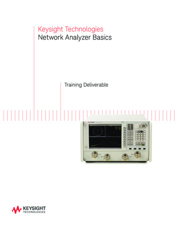
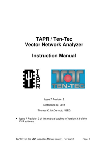
Conversion lossDefinition and importance ofconversion lossPower levelLOConversion lossFrequencyFigure 6. Conversion lossConv loss vs IF freq(fixed LO freq)RFConv loss vs RF freq(fixed IF freq)RFIFLO0IFLOLossLossConversion loss, as shown in Figure 6,measures how efficiently a mixerconverts energy from one frequencyto another. It is defined as the ratio ofthe output power to the input powerat a given LO (local oscillator) power.A specified LO power is necessarybecause while the conversion loss of amixer is usually very flat within thefrequency span of its intendedoperation, the average loss will varywith the level of the LO, as the diodeimpedance changes. As shown inFigure 7, conversion loss is usuallymeasured versus frequency, either theIF frequency (with a fixed LO) or theRF frequency (with a fixed IF). Theconfiguration for a fixed IF measurement is different from those describedup to this point. (See the Fixed IFMeasurement section.) Figure 8illustrates the importance of a flatconversion-loss response. The DUT isa standard television-channel converter. The input signal consists of a visualcarrier, audio carrier and a colorsubcarrier. Since the frequencyresponse of the converter has a notchin the passband, the color subcarrieris suppressed and the resulting outputsignal no longer carries a valid colorinformation signal.Conversion loss mag(f IF )20*log []mag(f RF)IFRF0IF freqRF freqFigure 7. Two types of conversion loss measurementsConverter olor sub-carrierattenuatedLOInput SignalDUTOutput signalFigure 8. TV tuner conversion loss example6
Measurement considerationsConversion-loss measurements can bemade with either a scalar networkanalyzer or a vector network analyzer,using the configurations shown inFigures 1 through 5. The measurement uncertainties are different foreach type of analyzer. For both typesof analyzers, the two main systematicerrors are port mismatch and frequency response. The scalar network analyzer approach requires additionalcare to minimize errors due to theanalyzer’s broadband detector. Forsome vector network analyzers, aninternal process, called sampling, andphase-lock requirements can also create errors. Next we will examine eachof these error terms and explore techniques to minimize their effects.Once the DUT is connected, interaction between the DUT’s ports and thenetwork analyzer’s ports cause mismatch errors. As shown in Figure 9,mismatch effects generate three firstorder error signals. The first isinteraction between the networkanalyzer’s source port and the DUT’sinput port. The second is between thenetwork analyzer’s receiver port andthe DUT’s output port.Mismatch errorsMismatch errors result when there isa connection between two ports thathave different impedances. Commonly,a device’s behavior is characterizedwithin a Z0 environment, typicallyhaving an impedance of 50 or 75 ohms.Although the test ports of a networkanalyzer are designed to be perfect Z0impedances, they are not. The imperfect source and receiver ports of thenetwork analyzer create errors in thecalibration stage. Therefore, evenbefore a device under test (DUT) isconnected, some errors have alreadybeen created in the calibration stage(see Figure 9). Once the DUT isconnected, the total measurementuncertainty is equal to the sum of thecalibration error plus the measurementerror.The third is between the networkanalyzer’s source port and receiverport. For an FTD measurement, thisthird interaction is usually negligiblebecause the conversion loss andisolation of the FTD will attenuate thereflected signals. As frequency translation precludes conventional two-porterror correction, attenuators can beused to improve port match.Calibration:SourceCalibration planeReceiverMeasurement:ρSourceDUTRFIFρsource receiverReceiverLO(ρρ)source DUT input(ρρ)receiver DUT output(ρρ)source receiverTotal Uncertainty Calibration Error Measurement ErrorFigure 9. Mismatch effects7
By adding a high-quality attenuator toa port, the effective port match isimproved by up to approximatelytwice the value of the attenuation.A high-quality attenuator has around32 dB of port match. The effectivematch is a function of the quality ofthe attenuator as well as its attenuation, as shown in Figure 10.ρE ff source matchAttenuatorSource(ρ)attenuator(ρsource )( attenuation ) 2ρ2E ff source match (ρattenuator ) (ρsource )( attenuation )Figure 10. Effective match as a function of attenuator’s match.Effective match (dB)3532 dB attenuator match3026 dB attenuator match2521 dB attenuator match2018 dB attenuator match15100510 15 20 25Original match (dB)3035Region when attenuatorno longer results in improved matchFigure 11. Effective match as a function of attenuator’s match (fixed 10 dB attenuator)35Effective match (dB)As shown in Figure 11 and Figure 12, awell-matched attenuator cansignifican
passband, the 8753E vector network analyzer has 35 dB of dynamic range in the R channel and provides a quick and easy solution To also measure the FTD’s relative phase and out-of-band response, Figure 4 illust