Transcription
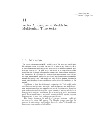
HP 8753E RF VectorNetwork AnalyzerTechnical Specifications30 kHz to 3 GHz or 6 GHzThe HP 8753E RF vector network analyzer providesall the performance and productivity features tosimplify and speed your component measurements in the30 kHz to 6 GHz frequency range. Its new processormakes measurement and data-transfer speeds up to seventimes faster than the previous model. Overall throughputis enhanced by new features such as simultaneous fourparameter display* and adapter-removal calibration. Anintegrated, synthesized source provides up to 10 mW ofoutput power (100 mW for Option 011), 1 Hz frequencyresolution, and linear-frequency, log-frequency, listfrequency, CW, and power sweep types. Three tunedreceivers allow independent power measurements orsimultaneous ratio measurements over a wide dynamicrange of 105 dB at 6 GHz (with Option 006 frequencyextension) or 110 dB at 3 GHz (standard). The integratedtest set allows you to measure transmission and reflectioncharacteristics of a device to 6 GHz, without a frequencydoubler.The HP 8753E network analyzer features two independentmeasurement channels. You can choose to display anycombination of reflection and transmission parameters,in magnitude, phase, group-delay, Smith-chart, polar, SWR,or time-domain formats. Softkeys let you quickly accessmeasurement functions, and you can view results in overlay or split-screen format on the LCD color display. AVGA-compatible output has been added to drive largerexternal monitors for optimum viewing.*available Q298HP 8753E maximizes versatilityand performance Frequency range from 30 kHz to 3 GHz, oroptionally 6 GHz. Built-in S-parameter test set provides completeforward and reverse measurements, allowing youto characterize your component with a singleconnection. 50 and 75-ohm solutions. Superb accuracy. Comprehensive calibrationguarantees accurate measurements. TRL*/LRM*make calibration in noncoaxial environments easierand more convenient. Mixer testing. Quickly and easily characterizefrequency translating devices such as mixers. Add swept harmonic measurements. Characterizeamplifier parameters — gain, 1 dB compression,match — and 2nd and 3rd harmonic distortion withthe same test setup. Built-in 3.5 inch floppy disk drive providesconvenient storage of instrument states and data. Parallel and serial ports provide interfaces topopular printers and plotters. The parallel portcan also be used as a general I/O bus, with usercontrollable TTL inputs and outputs. Users canalso connect a DIN keyboard to speed up entry oftitles, labels, or file names, and for remote frontpanel operation.
2Definitions and test conditionsThis document provides two types of performanceinformation:Specifications describe the instrument’s warranted performance over the temperature range of 23 3 C, unlessotherwise stated. Specifications for frequencies above 3GHz do not apply to instruments with Option 075 (75-ohmimpedance).Supplemental characteristics are typical but nonwarranted performance parameters. These are denotedas “typical,” “nominal,” or “approximate.”Dynamic rangeSystem dynamic range is the noise level relative to a“through.” It is calculated as the difference between themaximum receiver input level and the receiver’s noisefloor. System dynamic range applies to transmissionmeasurements only, since reflection measurements arelimited by directivity.Noise floor is specified as the mean of the noise trace overfrequency. A signal at this level would have a signal/noisepower ratio of 3 dB. Noise floor is measured with the testports terminated in loads, full two-port error correction(with 16 averages used during isolation), 10 Hz IF bandwidth (BW), maximum test port power, and no averagingduring the measurement.Measurement uncertaintyCurves show the worst-case magnitude and phase uncertainty for reflection and transmission measurements, aftera full two-port calibration (including isolation with anaveraging factor of 16) using the specified cal kit, with10 Hz IF bandwidth (BW) and no averaging.Calibration is the process of measuring known standardsfrom a calibration kit to characterize a network analyzer’ssystematic (repeatable) errors.Reflection measurement uncertainty is plotted as afunction of S11 (reflection coefficient, linear). The curvesassume a one-port device (S21 S12 0).Transmission measurement uncertainty is plotted as afunction of S21 (transmission gain/loss) in dB from thereference level. The curves assume that the device iswell-matched (S11 S22 0).The reference level for HP 8753E measurements is–10 dBm test port power.Measurement port characteristicsCorrected (residual) indicates performance after errorcorrection (calibration). It is determined by the quality ofcalibration standards and how well “known” they are, plussystem repeatability, stability, and noise.Uncorrected (raw) indicates intrinsic performancewithout error correction. This is related to the ultimatestability of a calibration.Organization of dataThe information in this document is organized into thefollowing sections. All data is subject to change.System performance summaryThe measurement uncertainty curves and measurementport characteristics given for HP 8753E systems alsoapply to the HP 8753E with Options 006 and 011 and theHP 85047A test set (50-ohm), or the HP 8753E Option 011with an HP 85046B test set (75-ohm).Test-port output characteristicsTest-port input characteristicsSeparate sections are provided for an HP 8753E (noOption 011), and HP 8753E with Option 011.Supplemental characteristicsHP 8753E test set specificationsThis section provides information on test sets that areavailable for use with the HP 8753E Option 011.HP 8753E accessoriesThese sections contain information about calibration kits,cables, adapters, and other accessories.
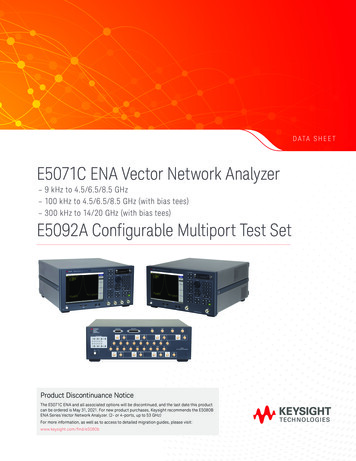
3System performance summaryHP 8753E (50-ohm systems) 7-mm test portsThe following specifications describe the system performance of the HP 8753E network analyzer with anintegrated 50-ohm S-parameter test set configuration.System hardware includes the following:Network analyzerCalibration kitTest-port cablesHP 8753E Option 006HP 85031BHP 11857DDynamic rangeThese specifications apply to transmission measurementsin the 30 kHz to 6 GHz frequency range at 10 Hz IF BWwith full two-port error correction. Dynamic range is limited by maximum receiver input level and the receiver’snoise floor.System dynamic range30 kHz to 300 kHz300 kHz to 1.3 GHz1.3 GHz to 3 GHz3 GHz to 6 GHzMeasurement port characteristicsThe following specifications show the residual HP 8753Esystem uncertainties for uncorrected performance andafter accuracy enhancement using full two-port errorcorrection. These characteristics apply for an environmental temperature of 25 5 C, with less than 1 C deviationfrom the calibration temperature.Frequency RangeCorrected30 kHz-300 kHz5 300 kHz-1.3 GHz 1.3 GHz-3 GHz55 dB55 dB51 dB46 dBSource Match55 dB51 dB49 dB43 dBLoad Match55 dB55 dB51 dB46 dB 0.001 dB 0.001 dB 0.005 dB 0.020 dBTransmission tracking 0.008 dB 0.006 dB 0.009 dB 0.021 dB25 dBReflection trackingUncorrected5100 dB1,6110 dB2110 dB105 dBSpecified measurement uncertainty3The following graphs show the specified measurementuncertainty for the HP 8753E over the full frequency rangeusing full two-port error correction.Directivity20 dB*35 dB30 dBSource Match18 dB**16 dB16 dB14 dBLoad Match20 dB**18 dB16 dB14 dBReflection tracking 2.0 dB 1.5 dB 1.5 dB 2.5 dBTransmission tracking 2.0 dB 1.5 dB 1.5 dB 2.5 dBCrosstalk100 dB100 dB90 dB90 dB*15 dB, 30 kHz to 50 kHz**10 dB, 30 kHz to 50 kHzTransmission measurementsMagnitudePhaseReflection measurements4Magnitude1.2.3.4.5.6.3 GHz- 6 GHzDirectivity90 dB, 30 kHz to 50 kHz.100 dB, 300 kHz to 16 MHz due to fixed spurs.These measurement uncertainty curves utilize an RSS model for the contribution of randomerrors such as noise, typical connector repeatabilities, and test set switch; with a worst-casemodel for the contributions of dynamic accuracy and residual systematic errors.The graphs shown for reflection measurements apply to either a one-port device or a two-portdevice with more than 6 dB insertion loss.Typical performance.Typical below 300 kHz.Phase
4System performance summaryHP 8753E (50-ohm systems) type-N test portsThe following specifications describe the system performance of the HP 8753E network analyzer with anintegrated 50-ohm S-parameter test set configuration.System hardware includes the following:Network analyzerCalibration kitTest-port cablesHP 8753E Option 006HP 85032BHP 11857DMeasurement port characteristicsThe following specifications show the residual HP 8753Esystem uncertainties for corrected performance afteraccuracy enhancement using full two-port error correction. These characteristics apply for an environmentaltemperature of 25 5 C, with less than 1 C deviationfrom the calibration temperature.Frequency rangeDynamic rangeThese specifications apply to transmission measurementsin the 30 kHz to 6 GHz frequency range at 10 Hz IF BWwith full two-port error correction. Dynamic range islimited by maximum receiver input level and the receiver’snoise floor.System dynamic range30 kHz to 300 kHz300 kHz to 1.3 GHz1.3 GHz to 3 GHz3 GHz to 6 GHzCorrected30 kHz-300 kHz5300 kHz-1.3 GHzDirectivity50 dB50 dB47 dB40 dBSource match49 dB42 dB36 dB31 dBLoad match50 dB50 dB47 dB40 dBReflection tracking 0.005 dB 0.009 dB 0.019 dB 0.070 dBTransmission tracking 0.014 dB 0.013 dB 0.026 dB 0.065 dB100 dB1,5110 dB2110 dB105 dBTypical measurement uncertainty3The following graphs show the typical measurementuncertainty for the HP 8753E over the full frequency rangeusing full two-port error correction.Transmission measurementsMagnitudePhaseReflection measurements4Magnitude1.2.3.4.5.1.3 GHz-3 GHz 3 GHz-6 GHz90 dB, 30 kHz to 50 kHz.100 dB, 300 kHz to 16 MHz due to fixed spurs.These measurement uncertainty curves utilize an RSS model for the contribution of randomerrors such as noise, typical connector repeatabilities, and test set switch; with a worst-casemodel for the contributions of dynamic accuracy and residual systematic errors.The graphs shown for transmission measurements assume a well-matched device (S11 S22 0).device with more than 6 dB insertion loss.Typical below 300 kHz.Phase
5System performance summaryHP 8753E (50-ohm systems) 3.5-mm test portsThe following specifications describe the system performance of the HP 8753E network analyzer with anintegrated 50-ohm S-parameter test set configuration.System hardware includes the following:Network analyzerCalibration kitTest-port cablesHP 8753E Option 006HP 85033DHP 11857DMeasurement port characteristicsThe following specifications show the residual HP 8753Esystem uncertainties for corrected performance afteraccuracy enhancement using full two-port error correction. These characteristics apply for an environmentaltemperature of 25 5 C, with less than 1 C deviationfrom the calibration temperature.Frequency RangeDynamic rangeThese specifications apply to transmission measurementsin the 30 kHz to 6 GHz frequency range at 10 Hz IF BWwith full two-port error correction. Dynamic range is limited by maximum receiver input level and the receiver’snoise floor.System dynamic range30 kHz to 300 kHz300 kHz to 1.3 GHz1.3 GHz to 3 GHz3 GHz to 6 GHzCorrected30 kHz-300 kHz5 300 kHz-1.3 GHz 1.3 GHz-3 GHz 3 GHz-6 GHzDirectivity49 dB46 dB44 dB38 dBSource Match49 dB44 dB41 dB37 dBLoad Match49 dB46 dB44 dB38 dBReflection tracking 0.010 dB 0.005 dB 0.007 dB 0.009 dBTransmission tracking 0.016 dB 0.014 dB 0.022 dB 0.048 dB100 dB1,5110 dB2110 dB105 dBTypical measurement uncertainty3The following graphs show the typical measurementuncertainty for the HP 8753E over the full frequencyrange using full two-port error correction.Transmission measurementsMagnitudePhaseReflection measurements4Magnitude1.2.3.4.5.90 dB, 30 kHz to 50 kHz.100 dB, 300 kHz to 16 MHz due to fixed spurs.These measurement uncertainty curves utilize an RSS model for the contribution of randomerrors such as noise, typical connector repeatabilities, and test set switch; with a worst-casemodel for the contributions of dynamic accuracy and residual systematic errors.The graphs shown for reflection measurements apply to either a one-port device or a two-portdevice with more than 6 dB insertion loss.Typical below 300 kHz.Phase
6System performance summaryHP 8753E (75-ohm systems) type-N test portsThe following specifications describe the system performance of the HP 8753E network analyzer with an integrated 75-ohm S-parameter test configuration. Systemhardware includes the following:Network analyzerCalibration kitTest-port cablesHP 8753E Option 075HP 85036BHP 11857BMeasurement port characteristicsThe following specifications show the residual HP 8753Esystem uncertainties for uncorrected performance andafter accuracy enhancement using full two-port error correction. These characteristics apply for an environmentaltemperature of 25 5 C, with less than 1 C deviationfrom the calibration temperature.Frequency RangeDynamic rangeThese specifications apply to transmission measurementsin the 30 kHz to 3 GHz frequency range at 10 Hz IF BWwith full two-port error correction. Dynamic range islimited by maximum receiver input level and the receiversnoise floor.Corrected530 kHz - 300 kHz300 kHz - 1.3 GHzDirectivity48 dB48 dB43 dBSource Match47 dB41 dB35 dBLoad Match1.3 GHz - 3 GHz48 dB48 dB43 dBReflection tracking 0.004 dB 0.010 dB 0.019 dBTransmission tracking 0.018 dB 0.015 dB 0.033 dBUncorrected5System dynamic range30 kHz to 300 kHz300 kHz to 1.3 GHz1.3 GHz to 3 GHz95 dB1,6105 dB2105 dBTypical measurement uncertainty3The following graphs show the typical measurementuncertainty for the HP 8753E over the full frequency rangeusing full two-port error correction.Directivity20 dB735 dB30 dBSource Match10 dB16 dB16 dBLoad Match14 dB18 dB16 dBReflection tracking 2.0 dB 1.5 dB 1.5 dBTransmission tracking 2.0 dB 1.5 dB 1.5 dB90 dB100 dB100 dBCrosstalkTransmission measurementsMagnitudePhaseReflection measurements4Magnitude1.2.3.4.5.6.7.90 dB, 30 kHz to 50 kHz.100 dB, 300 kHz to 16 MHz due to fixed spurs.These measurement uncertainty curves utilize an RSS model for the contribution of randomerrors such as noise, typical connector repeatabilities, and test set switch; with a worst-casemodel for the contributions of dynamic accuracy and residual systematic errors.The graphs shown for reflection measurements apply to either a one-port device or a two-portdevice with more than 6 dB insertion loss.Typical performance.Typical below 300 kHz.15 dB from 30 to 50 kHz.Phase
7System performance summaryHP 8753E (75-ohm systems) type-F test portsThe following specifications describe the system performance of the HP 8753E network analyzer with an integrated 75-ohm S-parameter test configuration. Systemhardware includes the following:Network analyzerCalibration kitTest-port cablesHP 8753E Option 075HP 85039BHP 11857BDynamic rangeThese specifications apply to transmission measurementsin the 30 kHz to 3 GHz frequency range at 10 Hz IF BWwith full two-port error correction. Dynamic range is limited by maximum receiver input level and the receiversnoise floor.System dynamic range30 kHz to 300 kHz300 kHz to 1.3 GHz1.3 GHz to 3 GHzMeasurement port characteristicsThe following specifications show the residual HP 8753Esystem uncertainties for uncorrected performance andafter accuracy enhancement using full two-port errorcorrection. These characteristics apply for an environmental temperature of 25 5 C, with less than 1 C deviationfrom the calibration temperature. Data is shown fortype-F female reflection port and type-F maletransmission port.Frequency RangeCorrected630 kHz-300 kHz300 kHz-1.3 GHz1.3 GHz-3 GHzDirectivity38 dB38 dB32 dBSource Match36 dB36 dB30 dBLoad Match38 dB38 dB32 dBReflection tracking 0.008 dB 0.008 dB 0.032 dBTransmission tracking 0.062 dB 0.035 dB 0.078 dB95 dB1,6105 dB2105 dBTypical measurement uncertainty3The following graphs show the typical measurementuncertainty for the HP 8753E over the full frequency rangeusing full two-port error correction.Transmission measurementsMagnitudePhaseReflection measurements4Magnitude1.2.3.4.5.6.90 dB, 30 kHz to 50 kHz.100 dB, 300 kHz to 16 MHz due to fixed spurs.These measurement uncertainty curves utilize an RSS model for the contribution of randomerrors such as noise, typical connector repeatabilities, and test set switch; with a worst-casemodel for the contributions of dynamic accuracy and residual systematic errors.The graphs shown for reflection measurements apply to either a one-port device or a two-portdevice with more than 6 dB insertion loss.Typical performance.Typical below 300 kHz.Phase
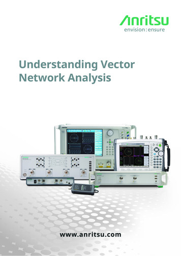
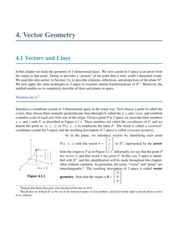
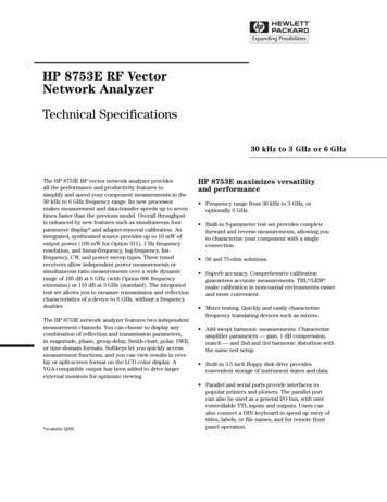
8HP 8753E specificationsTest-port output characteristics7Test port input characteristicsFrequency characteristicsRange30 kHz to 3 GHz (6 GHz with Opt. 006)Resolution1 HzStabilitytypically 7.5 ppm 0 to 55 Ctypically 3 ppm/yearWith Option 1D5typically 0.05 ppm 0 to 55 Ctypically 0.5 ppm/yearAccuracy 10 ppm at 25 C 5 CPower range–85 to 10 dBm2,6Resolution0.05 dBLevel accuracy1,2,5 1.0 dBLevel linearity1,2,5(–15 dBm to 5 dBm) 0.2 dB(5 dBm to 10dBm)6 0.5 dBImpedance50 Ω; typically 16 dB RL ( 1.38 SWR) to 3 GHz 14 dB RL ( 1.50 SWR) to 6 GHzSpectral purity2nd harmonic3 –25 dBc at 106 dBm –40 dBc at 0 dBm (typical) –50 dBc at –10 dBm (typical)3rd harmonic4 –25 dBc at 106 dBm –40 dBc at 0 dBm (typical) –50 dBc at –10 dBm (typical)Nonharmonic spuriousMixer related –30 dBc at 106 dBm (typical) –55 dBc at –10 dBm (typical)Frequency rangeAverage noise level2SourceRF Out30 kHzto 3 GHz3.8 to6.8 GHzMaximum input levelDamage levelImpedance, 50 ohms30 kHz to 3 GHz (6 GHz with Opt. 006)–82 dBm (3 kHz BW, 3 GHz)–102 dBm (10 Hz BW, 3 GHz)–110 dBm (10 Hz BW, 3 GHz) (typical)–77 dBm (3 kHz BW, 3 to 6 GHz)–97 dBm (10 Hz BW, 3 to 6 GHz)–105 dBm (10 Hz BW, 3 to 6 GHz) (typical)10 dBm26 dBm or 35 VDC 10 dB RL, 30 kHz to 50 kHz2 20 dB RL, 50 kHz to 300 kHz2 18 dB RL, 300 kHz to 1.3 GHz 16 dB RL, 1.3 GHz to 3 GHz 14 dB RL, 3 GHz to 6 GHz 1.0 dB, 300 kHz to 3 GHz 2.0 dB, 3 GHz to 6 GHzFrequency response2,5(25 5 C)Harmonics (Option 002)2nd harmonic3 –15 dBc at 8 dBm –35 dBc at 0 dBm (typical) –45 dBc at –15 dBm (typical)3rd harmonic4 –30 dBc at 8 dBm –50 dBc at 0 dBm (typical) –50 dBc at –15 dBm (typical)Harmonic measurement accuracy (25 5 C)16 MHz to 3 GHz 1.5 dB3 GHz to 6 GHz 3 dB (with Opt. 006)Harmonic measurement dynamic range–40 dBc (output –10 dBm,input –15 dBm)ReceiverBA/DA1 MHzR outR inR3.8 GHzMainProcessorROM/RAM4 kHzI/OFrontPanelPhase e Gen.HP 8753E block diagram1.2.3.4.5.6.7.At 25 C 5 C, relative to 0 dBm output power for the HP 8753E, 10 dBm output powerfor the HP 8753E Option 011.Typical below 300 kHz.16 MHz to 3 GHz.16 MHz to 2 GHz.Typical from 2 to 3 GHz for instruments with Option 075. 8 dBm with Option 075.Test performed on port 1 only.FastProcessor
9HP 8753E specificationsTest-port input characteristics (continued)Frequency offset mode3Frequency range300 kHz to 3 GHz(6 GHz with Opt. 006)R channel input requirementsPower level0 to –35 dBm to 3 GHz0 to –30 dBm, 3 GHz to 6 GHzSpectral purityMaximum spurious input –25 dBcResidual FM 20 kHzLO frequency accuracy–1 to 1 MHz of nominal frequencyExternal source mode4 (CW time sweep only)Frequency range300 kHz to 6 GHzR channel input requirements1Power level0 to –25 dBmSpectral purityMaximum spurious input –30 dBcResidual FM 20 kHzTypical settling time500 ms (automatic)50 ms (manual)Frequency readout accuracy0.1% typical (automatic)Input frequency margin1Manual: –0.5 to 5 MHzAutomatic: 50 MHz, 5 MHz 50 MHz, 10% CW frequencyAccuracy(See magnitude and phasecharacteristics)Display resolutionMarker resolution5Trace noise2Reference levelStability20.001 dB/division0.001 dB 0.006 dB rms, 30 kHz to 3 GHz 0.010 dB rms, 3 GHz to 6 GHz( 5 dBm at test-port, ratiomea
The HP 8753E network analyzer features two independent measurement channels. You can choose to display any combination of reflection and transmission parameters, in magnitude, phase, group-delay, Smith-chart, polar, SWR