Transcription
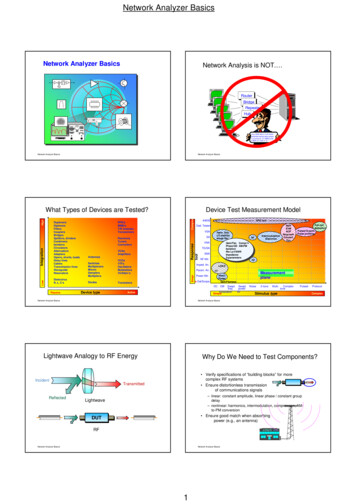
Network Analyzer BasicsNetwork Analyzer BasicsNetwork Analysis is NOT. RouterBridgeRepeaterHubYour IEEE 802.3 X.25 ISDNswitched-packet data streamis running at 147 MBPS with-9a BER of 1.523 X 10 . . .Network Analyzer BasicsNetwork Analyzer BasicsLowDielectricsR, L, C'sPassiveComplexRFICsMMICsT/R plersMultipliersDiodesDevice typeVCOsVTFsOscillatorsModulatorsVCAtten’sRFIC testHarm. Dist.LO stabilityImage Rej.VNATG/SASNANF Mtr.Param. An.Power Mtr.TransistorsDet/ScopeFull callsequencePulsed S-parm.Pulse /FlatnessDC CW Swept lat. Compr'nPhase/GD AM-PMIsolationRtn Ls/VSWRImpedanceS-parametersImped. An.Network Analyzer BasicsNoise2-toneMulti-ComplextonePulsed-Stimulus typeProtocolComplexNetwork Analyzer BasicsLightwave Analogy to RF EnergyIncidentReflected84000Ded. ltersCouplersBridgesSplitters, aptersOpens, shorts, loadsDelay linesCablesTransmission linesWaveguideResonatorsDevice Test Measurement ModelSimpleHighWhat Types of Devices are Tested?Why Do We Need to Test Components? Verify specifications of “building blocks” for morecomplex RF systems Ensure distortionless transmissionof communications signalsTransmitted– linear: constant amplitude, linear phase / constant groupdelay– nonlinear: harmonics, intermodulation, compression, AMto-PM conversionLightwave Ensure good match when absorbingpower (e.g., an antenna)DUTRFKPWRNetwork Analyzer BasicsNetwork Analyzer Basics1FM 97
Network Analyzer BasicsThe Need for Both Magnitude and PhaseAgendaS211. Completecharacterization oflinear networks S11S22S122. Complex impedanceneeded to designmatching circuits4. Time-domaincharacterization Mag3. Complex valuesneeded for devicemodelingHigh-frequency transistor modelTime 5. Vector-error correctionErrorBase CollectorMeasured What measurements do we make? Transmission-line basics Reflection and transmissionparameters S-parameter definitionNetwork analyzer hardware Signal separation devices Detection types Dynamic range T/R versus S-parameter test setsError models and calibration Types of measurement error One- and two-port models Error-correction choices Basic uncertainty calculationsExample measurementsAppendixActualEmitterNetwork Analyzer BasicsNetwork Analyzer BasicsTransmission line ZoTransmission Line Basics-I Zo determines relationship between voltage and currentwavesZo is a function of physical dimensions and εrZo is usually a real impedance (e.g. 50 or 75 ohms)1.5Twisted-pair1.3a1.2bHigh frequencies wavelength or length of transmissionmedium need transmission lines for efficient powertransmission matching to characteristic impedance (Z o) isvery important for low reflection and maximumNetwork Analyzer Basicspower transfer measured envelope voltage dependent onεrCoaxialw2Coplanar50 ohm standard1.00.90.8power handling capacitypeaks at 30 ohms0.6w0.5102030405060 70 80 90 100characteristic impedancefor coaxial airlines (ohms)MicrostripNetwork Analyzer BasicsTransmission Line Terminated with ZoZs ZoLoad Power(normalized)1.10.7w1RSFor complex impedances, maximumpower transfer occurs when ZL ZS*(conjugate match)Rs1.2hhPower Transfer EfficiencyRLattenuation islowest at 77 ohms1.4Waveguidenormalized values Low frequencies wavelengths wire length current (I) travels down wires easily for efficientpower transmission measured voltage and current not dependent onposition along wireZo characteristicimpedanceoftransmission lineZo jX1-jX0.8Vinc0.6RL0.40.2Vrefl 0! (all the incident poweris absorbed in the load)0012345678910RL / RSFor reflection, a transmission lineterminated in Zo behaves like an infinitelylong transmission lineMaximum power is transferred when RL RSNetwork Analyzer BasicsNetwork Analyzer Basics2
Network Analyzer BasicsTransmission Line Terminated with 25 ΩTransmission Line Terminated withShort, OpenZs ZoZs ZoZL 25 ΩVincVincVreflNetwork Analyzer BasicsVreflIn-phase (0o) for open,out-of-phase (180o) for shortFor reflection, a transmission lineterminated in a short or open reflectsall power back to sourceNetwork Analyzer BasicsHigh-Frequency Device CharacterizationReflection RVreflectedΓ VincidentReturn loss -20 log(ρ),BReflectedStanding wave patterndoes not go to zero aswith short or openAReflectedIncident ATransmittedRIncidentSWRS-ParametersS11, S22ReflectionCoefficientΓ, ρReturnLossImpedance,AdmittanceR jX,G jBρΦ ZL ZOZ L ZOΓ Voltage Standing WaveRatioEmaxVSWR Emin 1 ρ1-ρB RGroupDelayTransmissionCoefficientΤ,τFull reflection(ZL open, short)No reflection(ZL Zo)Gain / LossS-ParametersS21, S12ρEmaxEminTRANSMISSIONREFLECTION ρ1 dBRL0 dB1VSWR 0InsertionPhaseNetwork Analyzer BasicsNetwork Analyzer BasicsSmith Chart ReviewTransmission Parameters. jXPolar plane90oV IncidentDUT1.0.8V Transmitted.60 R.4 180 o-o.20Transmission Coefficient 0-jXRectilinear impedanceplane-90VConstant XΓ Γ 1V0 180ZL Γ 1O(open)0TransInsertion Loss (dB) - 20 LogConstant RZ L 0 (short) V Incident oZ L ZoSmith Chart mapsrectilinearimpedanceplane onto polarplaneV TransmittedΤVOGain (dB) 20 LogVSmith chartNetwork Analyzer BasicsNetwork Analyzer Basics3TransInc - 20 logInc 20 logτττ φ
Network Analyzer BasicsCriteria for Distortionless TransmissionLinear NetworksLinear Versus Nonlinear BehaviorA * Sin 360o * f (t - to)ALinear behavior: TimetoA phase shift to * 360o * fDUTInputFrequencyMagnitudef1TimeLinear phase overbandwidth ofinterestConstant amplitude overbandwidth of interestOutputFrequencyPhaseSin 360o * f * tinput and output frequencies arethe same (no additionalfrequencies created)output frequency only undergoesmagnitude and phase changeNonlinear behavior:f1 FrequencyTime fFrequency1output frequency mayundergo frequency shift(e.g. with mixers)additional frequenciescreated (harmonics,intermodulation)FrequencyNetwork Analyzer BasicsNetwork Analyzer BasicsPhase Variation with FrequencyMagnitude Variation with FrequencyF(t) sin wt 1 /3 sin 3wt 1 /5 sin 5wtF(t) sin wt 1/3 sin 3wt 1/5 sin 5wtLinear FrequencyFrequency0 FrequencyFrequency-360 Network Analyzer BasicsDeviation from Linear PhaseGroup DelayUse electrical delay toremove linear portion ofphase responseLinear electrical lengthaddedRF filter responseFrequencyωAverage delay φPhase 1 /DivoyieldsFrequencyGroup delay rippletoφPhaseDeviation from linearphaseoPhase 45 /Div tg ω(Electrical delay function)Low resolutionFrequency-180 FrequencyNetwork Analyzer BasicsFrequencyTimeFrequencyGroup Delay (tg) d φdωFrequencyφωφHigh resolution 1360 o*dφdf in radians/sec in degreesf in Hertz (ω 2 π f)Network Analyzer BasicsNetwork Analyzer Basics4 in radiansgroup-delay ripple indicates phase distortionaverage delay indicates electrical length of DUTaperture of measurement is very important
Network Analyzer BasicsCharacterizing Unknown DevicesUsing parameters (H, Y, Z, S) to characterizedevices:PhasePhaseWhy Measure Group Delay? ff d φdω GroupDelayGroupDelay d φdωgives linear behavioral model of our devicemeasure parameters (e.g. voltage and current) versusfrequency undervarious source and load conditions(e.g. short and open circuits)compute device parameters from measured datapredictcircuit performanceunder any sourceand V1 h11I1 h12V2I1 y11V1 y12V2V1 z11I1 z12I2I2 h21I1 h22V2I2 y21V1 y22V2V2 z21I1 z22I2ffSame p-p phase ripple can result in differentgroup delayNetwork Analyzer Basics V2 0(requires short circuit)h12 V1V2I1 0(requires open circuit)Network Analyzer BasicsMeasuring S-ParametersWhy Use S-Parameters? h11 V1I1Reflectedb1b1TransmittedS 21 Incidenta2 0b1 1Z0S 11ForwardS 11 SIncidenta1relatively easy to obtain at high frequencies measure voltage traveling waves with a vector network analyzer don't need shorts/opens which can cause active devices to oscillateor self-destructrelate to familiar measurements (gain, loss, reflection coefficient .)can cascade S-parameters of multiple devices to predict systemperformancecan compute H, Y, or Z parameters from S-parameters if desiredS 21IncidentTransmittedcan easily importanduse S-parameterfiles in our electronica1b2simulation tools S11a2 0S 22 2 a1a2 0S 12 ReflectedIncidentTransmittedIncidentb2 a2ba1 01 a2a1 0DUTS22Port 2 ReflectedPort 1a2IncidentSTransmitted12a1 0Z0DUTLoadb1 S11a1 S12 a 2b1b 2 S21 a1 S22 a 2Network Analyzer BasicsTransmittedS 12S 22b2ReverseReflecteda2IncidentNetwork Analyzer BasicsEquating S-Parameters with CommonMeasurement TermsCriteria for Distortionless TransmissionNonlinear Networks S11 forward reflection coefficient (input match)S22 reverse reflection coefficient (output match)S21 forward transmission coefficient (gain or loss)S12 reverse transmission coefficient (isolation) Remember, S-parameters areinherently complex, linearquantities -- however, we oftenexpress them in a log-magnitudeformatSaturation, crossover,intermodulation, and other nonlineareffects can cause signal distortionEffect on system depends on amountand type of distortion and systemarchitectureTimeFrequencyNetwork Analyzer BasicsNetwork Analyzer Basics5TimeFrequency
Network Analyzer BasicsWhat is the Difference BetweenNetwork and Spectrum Analyzers?Measuring Nonlinear Behavior8563ALPFSPECTRUM ANALYZER.RL 0 dBmATTEN10 dB10 dB / DIVMeasuresknownsignalAmplitude8563AAmplitude RatioMost common measurements: using a network analyzer andpower sweeps gain compression AM to PM conversion using a spectrum analyzer source(s) harmonics, particularly secondand third intermodulation products resultingfrom two or more RFcarriersSPECTRUM ANALYZERGHz9 k Hz -2 6.5MeasuresunknownsignalsFrequencyFrequency9 k Hz -2 6.5 GHzNetwork analyzers: DUT CENTER 20.00000 MHzRB 30 HzVB 30 HzLPFSPAN 10.00 kHzST 20 sec Network Analyzer BasicsSpectrum analyzers:measure components, devices,circuits, sub-assembliescontain source and receiverdisplay ratioed amplitude and phase(frequency or power sweeps)offer advanced error correction measure signal amplitude characteristicscarrier level, sidebands, harmonics.)can demodulate (& measure) complexsignalsare receivers only (single channel)can be used for scalar component test (nophase) with tracking gen. or ext. source(s)Network Analyzer BasicsAgendaGeneralized Network AnalyzerBlock Diagram IncidentWhat measurements do we make?Network analyzer hardwareError models and calibrationExample B)RECEIVER / DETECTORPROCESSOR / DISPLAYNetwork Analyzer BasicsNetwork Analyzer BasicsIncidentSourceSignal ATION INCIDENT ( R)Supplies stimulus for systemSwept frequency or powerTraditionally NAs used separatesourceMost Agilent analyzers soldtoday have integrated,synthesized sourcesREFL ECT ED(A)TRANSMITT ED(B)RECEIVER / DETECTORPROCESSOR / DISPLAY measure incident signal for referenceseparate incident and reflected signalssplitterbridgedirectionalcouplerNetwork Analyzer BasicsNetwork Analyzer Basics6DetectorTest Port
Network Analyzer BasicsInteraction of Directivity with theDUT (Without Error Correction)DirectivityDirectivity is a measure of how well acoupler can separate signals movingin opposite directionsData MaxDevice(desired reflectedsignal)DirectivityDUT RL 40 dBReturn Loss(undesired leakagesignal)030Add in-phase60DeviceFrequencyDirectivityDirectional CouplerNetwork Analyzer BasicsDeviceTest portData MinData Vector SumDirectivityAdd out-of-phase(cancellation)Network Analyzer BasicsIncidentDetector TypesTransmittedBroadband Diode DetectionDUTReflectedSOURCEScalar broadband(no phaseinformation)DiodeSIGNALSEPARATIONINCIDENT ( R)REFL ECT ED(A)TRANSMITT ED(B)RECEIVER / DETECTORPROCESSOR / DISPLAYDCEasy to make broadbandInexpensive compared to tuned receiver Good for measuring frequency-translating devices Improve dynamic range by increasing power Medium sensitivity / dynamic range RFAC Tuned ReceiverIF F LO F RFRFADC / DSPVector(magnitude andphase)IF FilterLO10 MHzNetwork Analyzer Basics26.5 GHzNetwork Analyzer BasicsNarrowband Detection - Tuned ReceiverComparison of Receiver TechniquesBroadband(diode)detectionADC / DSP0 dBBest sensitivity / dynamic range Provides harmonic / spurious signalrejection Improve dynamic range by increasingpower, decreasing IF bandwidth, oraveraging Trade off noise floor andmeasurement speed0 dBNarrowband(tuned-receiver)detection 10 MHz-50 dB-50 dB-100 dB-100 dB-60 dBm Sensitivityhigher noise floor false responses -100 dBm Sensitivity high dynamic rangeharmonic immunityDynamic range maximum receiver power receiver noise floor26.5 GHzNetwork Analyzer BasicsNetwork Analyzer Basics7
Network Analyzer BasicsT/R Versus S-Parameter Test SetsDynamic Range and AccuracySourceSource-10Transfer switch Error (dB, deg)S-Parameter Test SetTransmission/Reflection Test SetError Due to Interfering Signal100Dynamic rangeis very importantfor measurementaccuracy!phase error1magn error0.1RRBAPort 1Port RF always comes out port1 port 2 is always receiver response, one-port calNetwork Analyzer Basicsavailable-70Interfering signal (dB)Network Analyzer BasicsProcessor / DisplayIncidentPort 2Port 1DUT 0.001BA DUTRevRF comes out port 1 or port2forward and reversemeasurementstwo-port calibrationpossibleInternal Measurement AutomationTransmittedDUTSimple: recall statesMore powerful:50 MH-20GHzNETWORK ANYZERACTIVECHANNELC H 2 S TA R T 775. 000 000 MH zC H 1 S TA R T 775. 000 000 MH zReflectedENTRYS TO P 925. 000 000 MH zS TO P 925. 000 000 MH zH ldSOURCERESPONSEPA S S2C orP RmSIGNALSEPARATION880.435 000 M H z1PA S S1REFL ECT ED(A)STIMULUSH ldTRANSMITT ED(B)P Rm R CHANNELINSTRUMENTSTATED uplex er T est - Tx -A nt and Ant - RxTR LS 839.470 000 M H zCH2CH1S 12S 21log MA Glog MA G10 dB/10 dB/Test sequencing1C orINCIDENT(R)R E F 0 dBR E F 0 dBHP-IB STATUS1 - 1.2468 dB1 - 1.9248 dBPORT 1PORT 2RECEIVER / DETECTOR PROCESSOR / DISPLAYCH2 START 775.000 000 MHzCH1 START 775.000 000 MHz STOP 925.000 000 MHzSTOP 925.000 000 MHzHld PASS2IBASIC Cor markerslimit linespass/fail indicatorslinear/log formatsgrid/polar/SmithchartsPRm 880.435 000 MHz1available on 8753/ 8720familieskeystroke recordingsome advanced functionsABCDEFGHIJKLMNOPQRSTUVWXYZ0123456789 - / * ( ) & "" " , . / ? ; : ' [ ]1 ASSIGN @Hp8714 TO 8002 OUTPUT @Hp8714;"SYST:PRES; *WAI"3 OUTPUT @Hp8714;"ABOR;:INIT1:CONT OFF;*WAI"available on 8712 familysophisticated programscustom user interfaces4 OUTPUT @Hp8714;"DISP:ANN:FREQ1:MODE SSTOP"5 OUTPUT @Hp8714;"DISP:ANN:FREQ1:MODE CSPAN"6 OUTPUT @Hp8714;"SENS1:FREQ:CENT 175000000 HZ;*WAI"7 OUTPUT @Hp8714;"ABOR;:INIT1:CONT OFF;:INIT1;*WAI"8 OUTPUT @Hp8714;"DISP:WIND1:TRAC:Y:AUTO ONCE"9 OUTPUT @Hp8714;"CALC1:MARK1 ON"PASSHld10 OUTPUT @Hp8714;"CALC1:MARK:FUNC BWID"11 OUTPUT @Hp8714;"SENS2:STAT ON; *WAI"112 OUTPUT @Hp8714;"SENS2:FUNC 'XFR:POW:RAT 1,0';DET NBAN; *WAI"1CorPRm13 OUTPUT @Hp8714;"ABOR;:INIT1:CONT OFF;:INIT1;*WAI"Duplexer Test - Tx-Ant and Ant-Rx839.470 000 MHzCH2CH1S12S21log MAGlog MAG10 dB/10 dB/REF 0 dBREF 0 dB14 OUTPUT @Hp8714;"DISP:WIND2:TRAC:Y:AUTO ONCE"1 -1.2468 dB1 -1.9248 dB15 OUTPUT @Hp8714;"ABOR;:INIT1:CONT ON;*WAI"16 ENDNetwork Analyzer BasicsNetwork Analyzer BasicsAgilent’s Series of HF Vector AnalyzersAgilent’s LF/RF Vector AnalyzersMicrowave Combination NA / SA8510C series8720ET/ES series 13.5, 20, 40 GHzeconomicalfast, small, integratedtest mixers, high-poweramps 110 GHz in coaxhighest accuracymodular, flexiblepulse systemsTx/Rx moduletest4395A/4396B RF8712ET/ES series 1.3, 3 GHzlow costnarrowband andbroadbanddetectionIBASIC / LANE5100A/B8753ET/ES series 500 MHz (4395A), 1.8 GHz (4396B)impedance-measuring optionfast, FFT-based spectrum analysistime-gated spectrum-analyzer optionIBASICstandard test fixtures3, 6 GHzhighest RFaccuracyflexible hardwaremore featuresOffset and harmonicRF sweeps LF Network Analyzer BasicsNetwork Analyzer Basics8180, 300 MHzeconomicalfast, smalltarget markets: crystals, resonators, filtersequivalent-circuit modelsevaporation-monitor-function option
Network Analyzer BasicsAgendaSpectrum Analyzer / Tracking GeneratorRF in IF8563ASPECTRUM ANALYZER9 k Hz -2 6.5 GHzLO DUT Spectrum analyzer TG out f IFDUTTracking generatorWhy do we even need error-correction andcalibration? It is impossible to make perfect hardware It would be extremely expensive to make hardwaregood enough to eliminate the need for errorcorrectionKey differences from network analyzer: What measurements do wemake?Network analyzer hardwareError models and calibrationExample measurementsAppendixone channel -- no ratioed or phase measurementsMore expensive than scalar NA (but better dynamic range)Only error correction available is normalization (and possiblyopen-short averaging)Poorer accuracySmall incremental cost if SA is required for other measurementsNetwork Analyzer BasicsNetwork Analyzer BasicsMeasurement Error ModelingCalibration TopicsWhat measurements do wemake? Network analyzer hardware Error models and calibration measurement errors what is vector errorcorrection? calibration types accuracy examples calibration considerations Example measurements Appendix CAL-CREALSystematic errors due to imperfections in the analyzer and test setup assumed to be time invariant (predictable)Random errors vary with time in random fashion (unpredictable) main contributors: instrument noise, switch and connectorrepeatabilityDrift errors due to system performance changing after a calibration hasbeen done primarily caused by temperature eRANDOMDRIFTNetwork Analyzer BasicsNetwork Analyzer BasicsSystematic Measurement ErrorsTypes of Error Correction RACrosstalkDirectivityresponse (normalization)simple to performonly corrects for tracking errorsthrustores reference trace in memory,then does data divided by memoryvectorrequires more standardsrequires an analyzer that can measure phaseaccounts for all major sources of systematic error B DUT Frequency response reflection tracking (A/R) transmission tracking (B/R)SourceMismatchLoadMismatchSHORTS11aSix forward and six reverse errorterms yields 12 error terms for twoport devicesNetwork Analyzer BasicsNetwork Analyzer Basics9thruOPENS11mLOAD
Network Analyzer BasicsWhat is Vector-Error Correction? Reflection: One-Port ModelError AdapterIdealRF inProcess of characterizing systematic error termsmeasure known standardsremove effects from subsequent measurements1-port calibration (reflection measurements)only 3 systematic error terms measureddirectivity, source match, and reflection trackingFull 2-port calibration (reflection and transmission measurements)12 systematic error terms measuredusually requires 12 measurements on four known standards(SOLT)Standards defined in cal kit definition filenetwork analyzer contains standard cal kit definitionsCAL KIT DEFINITION MUST MATCH ACTUAL CAL KIT USED!User-built standards must be characterized and entered into usercal-kitRF in1ED Directivity S11AED S11A ActualTo solve for error terms,S11Awe measure 3 standardsS11M ED to generate 3 equations1ES S11AERTand 3 unknownsAssumes good termination at port two if testing two-port devicesIf using port 2 of NA and DUT reverse isolation is low (e.g., filter passband):assumption of good termination is not validtwo-port error correction yields better results S11M MeasuredERT ES
Network Analyzer Basics 3 Network Analyzer Basics Transmission Line Terminated with Short, Open Zs Zo Vrefl Vinc For reflection, a transmission line terminated in a short or open reflects all power back to source In-phase (0 o) for open, out-of-phase (180o) for short Network Analyzer Basics