Transcription
Series GMGas BoilersInstallation,Operation &MaintenanceManual
TABLE OF CONTENTSTABLE OF CONTENTSUSING THIS MANUAL1A. INSTALLATION SEQUENCE . . . . . . . . . . . . .1B. SPECIAL ATTENTION BOXES . . . . . . . . . . . .11. PREINSTALLATION2A. ACCESSIBILITY CLEARANCES . . . . . . . . . . .2B. CLEARANCE FROM COMBUSTIBLECONSTRUCTION . . . . . . . . . . . . . . . . . . . . . .2C. COMBUSTION AND VENTILATION AIR . . . .2D. INSTALLATION SURVEY . . . . . . . . . . . . . . . .5E. CIRCULATORS . . . . . . . . . . . . . . . . . . . . . . . .5F. PLANNING THE LAYOUT . . . . . . . . . . . . . . . .52. BOILER SET-UP63. WATER PIPING AND CONTROLS7A. BOILER SUPPLY AND RETURN . . . . . . . . . . .7B. SAFETY RELIEF VALVE . . . . . . . . . . . . . . . . .8C. PIPING FOR ZONED SYSTEMS . . . . . . . . . . .9D. EXPANSION TANK . . . . . . . . . . . . . . . . . . . .10E. INDIRECT-FIRED WATER HEATER . . . . . . .10F. FREEZE PROTECTION . . . . . . . . . . . . . . . . .107. CSD CODE REQUIREMENTS23A. GENERAL . . . . . . . . . . . . . . . . . . . . . . . . . . .23B. CSD PART CF REQUIREMENTS . . . . . . . . .23C. CSD PART CW REQUIREMENTS . . . . . . . .23D. CSD MODULAR AND MULTIPLE BOILERREQUIREMENTS . . . . . . . . . . . . . . . . . . . . .23E. CSD PART CE ELECTRICALREQUIREMENTS . . . . . . . . . . . . . . . . . . . . .248. START-UP PROCEDURES25A. COMPLETING THE INSTALLATION . . . . . . .25B. CONTROL DESCRIPTIONS . . . . . . . . . . . . .30C. ADJUSTMENT OF GAS PRESSUREREGULATOR . . . . . . . . . . . . . . . . . . . . . . . . .30D. CHECKING BURNER INPUT . . . . . . . . . . . . .30E. CHECK-OUT PROCEDURE . . . . . . . . . . . . . .319. TROUBLESHOOTING32A. SHUT-DOWN CAUSED BY PILOT OUTAGE,VENT SAFETY SHUTOFF SWITCH ORFLAME ROLLOUT SAFETY SHUTOFFSWITCH . . . . . . . . . . . . . . . . . . . . . . . . . . . .32B. TROUBLESHOOTING GUIDES . . . . . . . . . .324. VENTING11A. DRAFT HOOD . . . . . . . . . . . . . . . . . . . . . . .11B. AUTOMATIC VENT DAMPERINSTALLATION – GENERAL . . . . . . . . . . . .12C. VENT PIPING AND CHIMNEY . . . . . . . . . . .12D. BOILER REMOVAL FROM COMMONVENTING SYSTEM . . . . . . . . . . . . . . . . . . .1310. MAINTENANCE35A. GENERAL . . . . . . . . . . . . . . . . . . . . . . . . . . .36B. DAILY (WITH BOILER IN USE) . . . . . . . . . . .36C. WEEKLY (WITH BOILER IN USE) . . . . . . . . .36D. MONTHLY (WITH BOILER IN USE) . . . . . . .36E. ANNUALLY (BEFORE START OF HEATINGSEASON) . . . . . . . . . . . . . . . . . . . . . . . . . . .375. GAS PIPING11. BOILER DIMENSIONS & RATINGS146. ELECTRICAL16A. WIRING . . . . . . . . . . . . . . . . . . . . . . . . . . . . .16B. CIRCULATOR/ZONE VALVE WIRING . . . . . .16C. LOW WATER CUTOFF . . . . . . . . . . . . . . . . .163812. REPAIR PARTS39A. BASE . . . . . . . . . . . . . . . . . . . . . . . . . . . . . . .39B. GAS MANIFOLD, ORIFICE SPUDS, ANDMAIN BURNERS . . . . . . . . . . . . . . . . . . . . . .40C. BLOCK AND FLUE COLLECTOR . . . . . . . . .41D. JACKET . . . . . . . . . . . . . . . . . . . . . . . . . . . .42E. CONTROLS, DRAFT HOOD ANDAUTOMATIC VENT DAMPER . . . . . . . . . . .43
USING THIS MANUALUSING THIS MANUALA. INSTALLATION SEQUENCEFollow the installation instructions provided in thismanual in the order shown. The order of theseinstructions have been set in order to provide theinstaller with a logical sequence of steps that willminimize potential interferences and maximize safetyduring boiler installation.B. SPECIAL ATTENTION BOXESThroughout this manual you will see special attentionboxes intended to supplement the instructions and makespecial notice of potential hazards. These categoriesmean, in the judgment of PB Heat, LLC:DANGERIndicates a condition or hazard which will causesevere personal injury, death or major propertydamage.WARNINGIndicates a condition or hazard which may causesevere personal injury, death or major propertydamage.CAUTIONIndicates a condition or hazard which will or cancause minor personal injury or property damage.NOTICEIndicates special attention is needed, but not directlyrelated to potential personal injury or propertydamage.1
PREINSTALLATION1. PREINSTALLATIONNOTICEThe equipment must be installed in accordance with installation requirements of the authority havingjurisdiction or, in the absence of such requirements, to the current edition of the National Fuel Gas Code, ANSIZ223.1/NFPA 54 or CAN/CGA B149 Installation Codes.Where required by the authority having jurisdiction, the installation must conform to American Society ofMechanical Engineers Safety Code for Controls and Safety Devices for Automatically Fired Boilers, ASME CSD-1.Carefully read these instructions before beginning work. Understand all aspects of the installation. Contact your PB Heat salesrepresentative or customer service for help in answering questions.This boiler must be installed by a qualified contractor. The boiler warranty can be voided if the boiler is not installed, maintainedand serviced correctly.Install boiler with not less than 24" (610 mm) betweenthe top and front of the boiler and adjacent wall or otherappliance, when access is required for servicing.B. CLEARANCE FROM COMBUSTIBLECONSTRUCTIONThe design of this boiler is certified for alcove installationwith the following clearances from combustibleconstruction:1.2.3.4.5.6.Sides: 6" (152 mm)Top of Jacket: 36" (914 mm)Draft Hood: 6" (152 mm)Vent Pipe: 6" (152 mm )[1" (25 mm) for Type B vent]Rear of Jacket: 6" (152 mm)Hot Water Pipes: 1" (25 mm)WARNINGDo not install this boiler on combustible flooring.Boiler installation on combustible flooring is a firehazard.7. If it is necessary to build a non-combustible floor padover top of an existing combustible floor, constructpad as stated in the current edition of National FuelGas Code Handbook under “Installation of SpecificEquipment”, or CAN/CGA B149 Installation Codesunder “General”.WARNINGDo not install boiler on carpeting. Boiler installationon carpeting is a fire hazard.C. COMBUSTION AND VENTILATION AIR1. Provide adequate facilities for combustion andventilation air in accordance with current edition ofNational Fuel Gas Code under “Air for Combustionand Ventilation”, or applicable provisions of the localbuilding code, or CAN/CGA B149 InstallationCodes. Subsections 2 through 8 below are based onNational Fuel Gas Code requirements.2. Required Combustion Air Volume: The total requiredvolume of indoor air is to be the sum of the requiredvolumes for all appliances located within the space.Rooms communicating directly with the space inwhich the appliances are installed and throughcombustion air openings sized as indicated inSubsection 3 are considered part of the requiredvolume. The required volume of indoor air is to bedetermined by one of two methods.a. Standard Method: The minimum requiredvolume of indoor air (room volume) shall be 50cubic feet per 1000 BTU/Hr (4.8 m3/kW). Thismethod is to be used if the air infiltration rate isunknown or if the rate of air infiltration is knownto be greater than 0.6 air changes per hour. Asan option, this method may be used if the airinfiltration rate is known to be between 0.6 and0.4 air changes per hour. If the air infiltration rateis known to be below 0.4 then the Known AirInfiltration Rate Method must be used. If thebuilding in which this appliance is to be installedis unusually tight, PB Heat recommends that theair infiltration rate be determined.b. Known Air Infiltration Rate Method: Wherethe air infiltration rate of a structure is known,the minimum required volume of indoor air forappliances other than fan assisted and for theSeries GM Boiler shall be determined as follows:Required Volumeother 221 ft3ACH I other 1000Btu/hr A. ACCESSIBILITY CLEARANCES
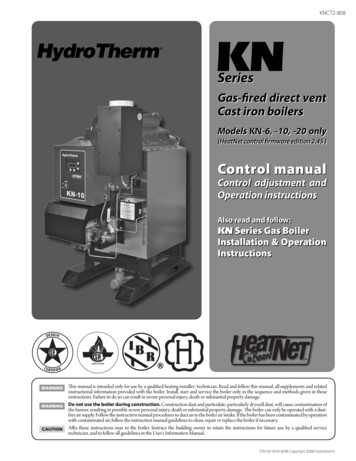
PREINSTALLATIONwhere:Iother Input of appliances other than fanassisted in Btu/hrACH air change per hour (percent of thevolume of the space exchanged perhour, expressed as a decimal)For fan assisted appliances, calculate the requiredvolume of air using the following equation:15 ft3ACH I fan 1000Btu/hr Required Volumefan Ifan Input of the fan assisted appliances inBtu/hrNote: These calculations are not to be used forinfiltration rates greater than 0.60 ACH.3. Indoor Air Opening Size and Location: Openingsconnecting indoor spaces shall be sized and locatedas follows:a. Combining spaces on the same floor:Provide two permanent openings communicatingwith additional spaces that have a minimum freearea of 1 in² per 1000 Btu/hr (22 cm² per 1000 W)of the total input rating of all gas fired equipmentbut not less than 100 in² (645 cm²). Oneopening is to begin within 12 inches (305 mm)of the top of the space and the other is to beginwithin 12 inches (305 mm) of the floor. Theminimum dimension of either of these openingsshall be 3 inches (76 mm). See Figure 1.1 for anillustration of this arrangement.Figure 1.2:4. Outdoor Combustion Air: Outdoor combustion air isto be provided through one or two permanentopenings. The minimum dimension of these airopenings is 3 inches (76 mm).a. Two Permanent Opening Method: Providetwo permanent openings. One opening is tobegin within 12 inches (305 mm) of the top ofthe space and the other is to begin within 12inches (305 mm) of the floor. The openings areto communicate directly or by ducts with theoutdoors or with spaces that freely communicatewith the outdoors. The size of the openings shallbe determined as follows:i.Figure 1.1:Air Openings – All Air from Indoorson Different FloorsWhere communicating directly or throughvertical ducts with the outdoors each openingshall have a minimum free area of 1 in² per4000 Btu/hr (22 cm² per 4000 W) of totalinput rating for all equipment in the space.See Figure 1.3 for openings directlycommunicating with the outdoors or Figure1.4 for openings connected by ducts to theoutdoors.Air Openings – All Air from Indoorson the Same Floorb. Combining spaces on different floors:Provide one or more permanent openingscommunicating with additional spaces that havea total minimum free area of 2 in² per 1000Btu/hr (44 cm² per 1000 W) of total input ratingof all equipment. See Figure 1.2 for anillustration of this arrangement. D.LIQUEFIED PETROLEUM (LP) GASFigure 1.3:Air Openings – All Air Directly fromOutdoors3
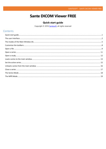
PREINSTALLATIONFigure 1.4:Air Openings – All Air from Outdoorsthrough Vertical Ductsii. Where communicating with the outdoorsthrough horizontal ducts, each opening shallhave a minimum free area of 1 in² per 2000Btu/hr (22 cm² per 2000 W) of total ratedinput for all appliances in the space. SeeFigure 1.5.Figure 1.6:Air Openings – All Air from Outdoorsthrough One Opening5. Combination Indoor and Outdoor Combustion Air: Ifthe required volume of indoor air exceeds theavailable indoor air volume, outdoor air openings orducts may be used to supplement the availableindoor air provided:a. The size and location of the indoor openingscomply with Subsection 3.b. The outdoor openings are to be located inaccordance with Subsection 4.c. The size of the outdoor openings are to be sizedas follows: V 1 – availVreq Areq Afull xwhere:Areq minimum area of outdoor openings.Afull full size of outdoor openings calculatedin accordance with Subsection 4.Vavail available indoor air volumeVreq required indoor air volumeFigure 1.5:Air Openings – All Air from Outdoorsthrough Horizontal Ductsb. One Permanent Opening Method: Provideone permanent opening beginning within 12inches (305 mm) of the top of the space. Theopening shall communicate directly with theoutdoors, communicate through a vertical orhorizontal duct, or communicate with a spacethat freely communicates with the outdoors. Theopening shall have a minimum free area of 1 in²per 3000 Btu/hr of total rated input for allappliances in the space and not less than thesum of the cross-sectional areas of all ventconnectors in the space. The gas-fired equipmentshall have clearances of at least 1 inch (25 mm)from the sides and back and 6 inches (150 mm)from the front of the appliance. See Figure 1.6for this arrangement.46. Engineered Installations: Engineered combustion airinstallations shall provide an adequate supply ofcombustion, ventilation, and dilution air and shall beapproved by the authority having jurisdiction.7. Mechanical Combustion Air Supply:a. In installations where all combustion air isprovided by a mechanical air supply system, thecombustion air shall be supplied from theoutdoors at the minimum rate of 0.35 ft3/min per1000 Btu/hr (0.034 m3/min per 1000 W) of thetotal rated input of all appliances in the space.b. In installations where exhaust fans are installed,additional air shall be provided to replace theexhaust air. GAS
PREINSTALLATIONg. The remaining space surrounding a chimneyliner, gas vent, special gas vent, or plastic pipinginstalled within a masonry, metal, or factory builtchimney shall not be used to supply combustionair.c. Each of the appliances served shall beinterlocked to the mechanical air supply toprevent main burner operation when themechanical air supply system is not in operation.d. In buildings where the combustion air is providedby the mechanical ventilation system, the systemshall provide the specified combustion air rate inaddition to the required ventilation air.h. Combustion air intake openings located on theexterior of buildings shall have the lowest side ofthe combustion air intake opening at least 12inches (305 mm) above grade.8. Louvers & Grills:a. The required size of openings for combustion,ventilation, and dilution air shall be based on thenet free area of each opening.i.Where the free area through a louver or grilleis known, it shall be used in calculating theopening size required to provide the free areaspecified.WARNINGLiquefied Petroleum (LP) is heavier than air and maycollect or “pool” in a low area in the event of a leakfrom defective equipment. This gas may then ignite,resulting in a fire or explosion.D. INSTALLATION SURVEYFor new and existing installations, a Water InstallationSurvey is available from PB Heat. The survey willprovide information on how a hot water boiler workswith your specific system and will provide an overviewof hot water system operation in general.ii. Where the free area through a louver or grilleis not known, it shall be assumed that woodenlouvers will have 25% free area and metallouvers and grilles will have 75% free area.iii. Nonmotorized dampers shall be fixed in theopen position.b. Motorized dampers shall be interlocked with theequipment so that they are proven in the fullopen position prior to ignition and duringoperation of the main burner.i.The interlock shall prevent the main burnerfrom igniting if the damper fails to openduring burner startup.E. CIRCULATORSThe Series GM boiler is not equipped with a circulatoror a means to control circulator operation. Providecirculator and zone controls, such as Taco zoningcirculator or Honeywell R845.F.PLANNING THE LAYOUTPrepare sketches and notes of the layout to minimize thepossibility of interferences with new or existingequipment, piping, venting and wiring.ii. The interlock shall shut down the burner ifthe damper closes during burner operation.9. Combustion Air Ductsa. Ducts shall be constructed of galvanized steel oran equivalent corrosion- resistant material.b. Ducts shall terminate in an unobstructed space,allowing free movement of combustion air to theappliances.c. Ducts shall serve a single space.d. Ducts shall not serve both upper and lowercombustion air openings where both suchopenings are used. The separation between ductsserving upper and lower combustion airopenings shall be maintained to the source ofcombustion air.e. Ducts shall not be screened where terminating inan attic space.f. Horizontal upper combustion air ducts shall notslope downward toward the source of thecombustion air.5
BOILER SET-UP2. BOILER SET-UP61. Provide a sound, level foundation. Locate boiler asnear to the chimney or outside wall as possible andcentralized with respect to the heating system.3. Separate the wood shipping pallet from the boilerbase by removing two (2) hold-down bolts at eachend of the boiler base.2. Locate boiler in front of installation position beforeremoving crate.4. Move boiler into final position.
WATER PIPING AND CONTROLS3. WATER PIPING AND CONTROLSDesign piping and size circulator(s) to suit the system. Refer tothe I B R - Residential Hydronic Heating Installation/DesignGuide and the PB Heat Water Survey for guidance.A. BOILER SUPPLY AND RETURNInstall boiler to protect the gas ignition systemcomponents from water (dripping, spraying, etc.) duringappliance operation and service (circulator replacement,condensate trap, control replacements, etc.).1. Remove shipping nipple from supply tapping.2. Install temperature-pressure gage with tee insupply tapping. Nipple, tee, bushing and gage arelocated in trim carton. See Figure 3.1.3. Install drain valve. Remove jacket front panel.Install drain valve with tee in return tapping. Nipple,tee, bushing and drain valve are located in trimcarton. See Figure 3.3. Tee may be installed with runin either horizontal or vertical orientation.Figure 3.1: Temperature-Pressure Gage Installation4. Install supply piping, return piping and circulator.See Figure 3.2.a. If boiler is installed above radiation level, providea low water cutoff device in the supply pipingabove boiler. See Figure 3.2.Figure 3.2: Typical Supply and Return Piping7
WATER PIPING AND CONTROLSb. When system return water temperature will bebelow 130 F (54 C), pipe the boiler with abypass arrangement to blend the system returnand hot supply to obtain at least 130 F (54 C)entering the boiler. For more information onbypass piping, consult the PB Heat WaterInstallation Survey.c. If this boiler and distribution system is used inconjunction with a refrigeration system, pipe thechilled medium in parallel with the boiler andinstall the proper valve to prevent the chilledmedium from entering the boiler. See Figure 3.4.d. When the boiler is connected to heating coilslocated in air handling units where they may beexposed to refrigerated air circulation, install flowcontrol valves or other automatic means toprevent gravity circulation of the boiler waterduring the cooling cycle.Figure 3.3: Drain Valve InstallationB. SAFETY RELIEF VALVE1. Locate safety relief valve and nipple in trim carton.2. Install safety relief valve in 3/4 NPT tapping behindsupply tapping. Safety relief valve must be installedwith spindle in vertical position. See Figure 3.5.CAUTIONPipe the discharge of safety relief valve to preventinjury in the event of pressure relief. Pipe thedischarge to a drain. Provide piping that is the samesize as the safety relief valve outlet.Figure 3.4: Parallel Hook-up with Water ChillerFigure 3.5: Safety Relief Valve Installation8
WATER PIPING AND CONTROLSC. PIPING FOR ZONED SYSTEMS1. See Figures 3.6 and 3.7 for basic zoned systemlayouts. Circulators may be installed in either supplyor return piping. Refer to PB Heat Water InstallationSurvey for additional information.2. Run each zone pipe down then up to zone toprevent air accumulation in piping.3. If required, provide means to isolate and drain eachzone separately.Figure 3.6: Zone Piping with Zone ValvesFigure 3.7: Zone Piping with Circulators9
WATER PIPING AND CONTROLSD. EXPANSION TANKF.For new or existing systems that must be freezeprotected:1. Consult the tank manufacturer’s instructions forspecific information relating to tank installation. Sizethe expansion tank for the required system volumeand capacity. See Table 11.1 for boiler’s watercontent.2. Expansion tanks are available with built-in fill valvesand check valves for reducing supply water pressureand maintaining minimum system pressure. Checkthe design features of the tank and provide valves asnecessary.FREEZE PROTECTIONWARNINGUse only inhibited propylene glycol solutions of up to50% by volume with water. Ethylene glycol is toxicand can attack gaskets and seals used in hydronicsystems.Refer to Figure 3.2 for typical expansion tank piping.E. INDIRECT-FIRED WATER HEATERBoiler may be used as heat source for indirect-firedwater heater. Refer to Figure 3.8 for typical piping.Follow the instructions provided by the water heatermanufacturer. Pipe the water heater as if a separatespace heating zone.1. Glycol for hydronic applications is speciallyformulated with inhibitors which prevent the glycolfrom attacking metallic system components. Makecertain that the system fluid is checked for thecorrect glycol concentration and inhibitor level.2. Antifreeze solutions expand more than water. Forexample, a 50% by volume solution expands 4.8%in volume for a temperature increase from 32 F(0 C) to 180 F (82 C), while water expands 3% withthe same temperature rise. Allowance must be madefor this expansion in system design.3. For more information, consult the PB Heat WaterInstallation Survey and the antifreeze manufacturer.Figure 3.8: Typical Piping with Indirect-Fired Water Heater10
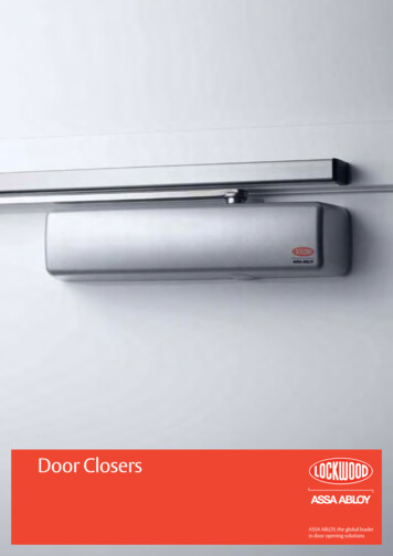
VENTING4. VENTINGA. DRAFT HOOD1. The boiler is equipped with a draft hood designed to:a. provide for the ready escape of flue gases fromthe boiler in the event of no draft.b. prevent a backdraft from entering the boiler.c. control stack draft during operation.The draft hood must be installed without alteration.Make certain there are no obstructions to airflow tothe relief opening.2. Position draft hood with 1" (25 mm) diameter hole inconical portion of draft hood (for vent safety shutoffswitch) towards front right corner of boiler. Secure toflue collector with sheet metal screws. See Figure 4.1.3. The boiler is equipped with a vent safety shutoffswitch. The switch is shipped in a cloth bag attachedto the harness on the exterior of the boiler. Attachswitch to holes in the conical portion of the drafthood using the screws provided in bag. SeeFigure 4.1.Figure 4.1: Draft Hood and Vent Safety ShutoffSwitch InstallationVent safety shutoff switch wiring harness must extendto vent safety shutoff switch without excessive slack.To adjust harness length, squeeze strain relief bushingto release from jacket. Adjust harness to properlength. Reinsert strain relief bushing.Figure 4.2: Venting Multiple Appliances11
VENTINGB. AUTOMATIC VENT DAMPERINSTALLATION – GENERALC. VENT PIPING AND CHIMNEY1. Do not use one vent damper to control two or moreheating appliances. See Figure 4.2.2. Follow these and the installation instructions includedwith the vent damper. Observe the cautions andwarnings that accompany all instructions.3. Provide minimum 6 inch (152 mm) clearancebetween automatic vent damper and combustibleconstruction. Increase clearance if required by ventdamper manufacturer’s instructions. Provideadequate space for vent damper access and service.2. Inspect the existing chimney and lining for structuralsoundness, corrosion and perforations. Repair asnecessary.3. Install vent pipe to slope upward at least 1/4" perlineal foot (21 mm per meter) between the drafthood outlet and the chimney.4. The automatic vent damper can be mounted directlyonto the draft hood outlet or in vent piping close tothe boiler.4. Before connection of joints, inspect the vent pipeinterior for foreign objects such as tools, equipment,rags, etc. and remove if present.See Figure 4.3 for installation with vent dampermounted in vertical position. See Figure 4.4 forinstallation with vent damper mounted in horizontalposition. Mount the unit to avoid excessive heat onthe operator or condensation drips into the operator.5. Insert vent pipe into but not beyond the inside wallof the chimney flue.a. Orient the vent damper operator to facilitateconnection of the vent damper harness toknockout on right side of boiler. See Figure 6.1.b. Orient vent damper direction arrow in directionof vent gas flow. Direction arrow must be visiblefrom front of boiler.Figure 4.3: Venting with Vent Damper in Vertical Position121. Install vent piping in accordance with current editionof National Fuel Gas Code, ANSI Z223.1/NFPA 54under “Venting of Equipment”, or applicableprovisions of the local building codes, or CAN/CGAB149 Installation Codes.6. Do not connect vent connectors serving appliancesvented by natural draft into any portion ofmechanical draft systems operating under positivepressure.7. Support horizontal portions of the venting system toprevent sagging by use of metal strapping orequivalent means. Locate supports at no more thanfour (4) foot (122 cm) intervals, or in accordance withvent system manufacturer’s installation instructions.
VENTINGFigure 4.4: Venting with Vent Damper in Horizontal PositionD. BOILER REMOVAL FROM COMMONVENTING SYSTEMAt the time of removal of an existing boiler, follow thesesteps with each appliance remaining connected to thecommon venting system placed in operation, while theother appliances remaining connected to the commonventing system are not in operation:a. Seal any unused openings in the common ventingsystem.b. Visually inspect the venting system for proper sizeand horizontal pitch and determine there is noblockage or restriction, leakage, corrosion and otherdeficiencies which could cause an unsafe condition.c. Insofar as is practical, close all building doors andwindows and all doors between the space in whichthe appliances remaining connected to the commonventing system are located and other spaces of thebuilding. Turn on any clothes dryers and anyappliance not connected to common venting system.Turn on any exhaust fans, such as range hoods andbathroom exhausts, so they will operate at maximumspeed. Do not operate a summer exhaust fan. Closefireplace dampers.d. Place in operation the appliance being inspected.Follow the lighting instructions. Adjust thermostat soappliance will operate continuously.e. Test for spillage at the draft hood relief opening after5 minutes of main burner operation. Use the flameof a match or candle, or smoke from a cigarette,cigar, or pipe.f. After it has been determined that each applianceremaining connected to the common venting systemproperly vents when tested as outlined above, returndoors, windows, exhaust fans, fireplace dampers andany other gas-burning appliance to their previousconditions of use.g. Any improper operation of the common ventingsystem should be corrected so that the installationconforms with the National Fuel Gas Code, ANSIZ223.1/NFPA 54 or CAN/CGA B149 InstallationCodes. When resizing any portion of the commonventing system, the common venting system shouldbe resized to approach minimum size as determinedusing the appropriate tables located in the chapter“Sizing of Category I Venting Systems,” of theNational Fuel Gas Code, ANSI Z223.1/NFPA 54 orCAN/CGA B149 Installation codes.13
GAS PIPING5. GAS PIPING1. Size and install the gas supply piping to provide asupply of gas sufficient to meet the maximumdemand of all appliances without undue loss ofpressure between the meter and the boiler.Maximum permissible gas supply pressure to theboiler is 13.5 inches (3.4 kPa) water column.2. Determine the volume of gas to be provided to theboiler. Obtain this value by dividing the Btu per hour(Watts) rating (on the boiler rating plate) by theheating value of the gas in Btu per cubic feet (Joulesper cubic meter). Obtain the heating value of the gasfrom the gas supplier. As an alternative, use Table5.1 to obtain the volume of gas to be provided tothe boiler.Table 5.1: InputNatural GasLP Gas(Cubic Feet(Cubic Meter(Cubic Feet(Cubic MeterModelPer Hour)Per Hour)Per Hour)Per 373.9GM-0839911.31604.5Natural gas based on 1000 Btu/Cubic Foot (37,300 kJ/m³).LP gas based on 2,500 Btu/Cubic Foot (93,145 kJ/m³).3. Table 5.2 shows the maximum flow capacity ofseveral pipe sizes based on 0.3" w.c. (.08 kPa) ofwater pressure drop. These values are based on aspecific gravity of 0.60. Apply the factors indicated inTable 5.3 for gas with specific gravity other than 0.60to obtain corrected capacities.Table 5.2: Capacity of Schedule 40 PipeCapacity of Schedule 40 pipe [cu. ft. per hour (cu. m perhour)] with pressure drop of 0.3 in. (75 Pa) and specific gravityof 0.60. No allowance for an ordinary number of fittings .³1,050730590500440400m³3021171412114. Connection of boiler to the gas piping system maybe made on the left side or top of the boiler. SeeFigure 11.1 for jacket opening locations.WARNINGUse a pipe joint sealing compound that is resistant tothe action of liquefied petroleum gas. A non-resistantcompound may lose sealing ability in the presence ofthis gas, resulting in a gas leak and fire or explosionpotential.5. Install a sediment trap. See Figure 5.1. Locate a teein the drop pipe at same elevation as the gas inletconnection to the boiler. Extend the drop pipe to apipe cap. As an alternate, the sediment trap may belocated in the boiler vestibule. See Figure 5.2.6. Install a ground joint union ahead of the gas controlassembly to permit servicing of the control. Somelocal codes require an additional equipment shutoffvalve when using the combination gas controls. Ifyour code requires such a valve, a suggestedlocation is shown in Figure 5.1 or 5.2.7. Check piping for leaks. Use an approved gasdetector, a non-corrosive leak detection fluid or otherleak detection method. If leaks are found, turn off allgas flow and repair as necessary.WARNINGWhen checking for leaks, do not use matches,candles, open flames or other methods that provide asource of ignition. This can ignite a gas leak,resulting in fire or explosion.1-1/2"Pipeft.³m³1,600 451,100 3125890227601967017610Table 5.3: Maximum Capacity Correction FactorsSpecific Gravity other than 0.60Specific GravityCorrection FactorSpecific GravityCorrection FactorSpecific GravityCorrection 0.610.700.931.100.741.700.590.750.901.200.711.800.
This boiler must be installed by a qualified contractor. The boiler warranty can be voided if the boiler is not installed, maintained and serviced correctly. Do not install this boiler on combustible flooring. Boiler installation on combustible flooring is a fire hazard. WARNING Do not install boiler on carpeting. Boiler installation