Transcription
EnglishIND560TerminalInstallation Manual
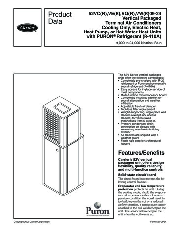
No part of this manual may be reproduced or transmitted in any form or by anymeans, electronic or mechanical, including photocopying and recording, for anypurpose without the express written permission of METTLER TOLEDO.U.S. Government Restricted Rights: This documentation is furnished withRestricted Rights.Copyright 2005 METTLER TOLEDO. This documentation contains proprietaryinformation of METTLER TOLEDO. It may not be copied in whole or in partwithout the express written consent of METTLER TOLEDO.METTLER TOLEDO reserves the right to make refinements or changes to theproduct or manual without notice.COPYRIGHT METTLER TOLEDO is a registered trademark of METTLER TOLEDO. All otherbrand or product names are trademarks or registered trademarks of theirrespective companies.METTLER TOLEDO RESERVES THE RIGHT TO MAKE REFINEMENTSOR CHANGES WITHOUT NOTICE.FCC NoticeThis device complies with Part 15 of the FCC Rules and the Radio InterferenceRequirements of the Canadian Department of Communications. Operation issubject to the following conditions: (1) this device may not cause harmfulinterference, and (2) this device must accept any interference received, includinginterference that may cause undesired operation.This equipment has been tested and found to comply with the limits for a ClassA digital device, pursuant to Part 15 of FCC Rules. These limits are designed toprovide reasonable protection against harmful interference when the equipmentis operated in a commercial environment. This equipment generates, uses, andcan radiate radio frequency energy and, if not installed and used in accordancewith the instruction manual, may cause harmful interference to radiocommunications. Operation of this equipment in a residential area is likely tocause harmful interference in which case the user will be required to correct theinterference at his or her own expense.Declaration of conformity is located on the documentation CD.English METTLER TOLEDO 2005
READ this manual BEFORE operating or servicing this equipment and FOLLOWthese instructions carefully. SAVE this manual for future reference.WARNING!FOR CONTINUED PROTECTION AGAINST SHOCK HAZARD CONNECT TOPROPERLY GROUNDED OUTLET ONLY. DO NOT REMOVE THE GROUNDPRONG.CAUTIONBEFORE CONNECTING/DISCONNECTING ANY INTERNAL ELECTRONIC COMPONENTS ORINTERCONNECTING WIRING BETWEEN ELECTRONIC EQUIPMENT ALWAYS REMOVE POWERAND WAIT AT LEAST THIRTY (30) SECONDS BEFORE ANY CONNECTIONS ORDISCONNECTIONS ARE MADE. FAILURE TO OBSERVE THESE PRECAUTIONS COULD RESULTIN DAMAGE TO OR DESTRUCTION OF THE EQUIPMENT AND/OR BODILY HARM.CAUTIONOBSERVE PRECAUTIONS FOR HANDLING ELECTROSTATIC SENSITIVE DEVICES.WARNING!A. NOT ALL VERSIONS OF THE IND560 ARE DESIGNED FOR USE INHAZARDOUS (EXPLOSIVE) AREAS. REFER TO THE DATA PLATE OF THEIND560 TO DETERMINE IF A SPECIFIC TERMINAL IS APPROVED FOR USEIN AN AREA CLASSIFIED AS HAZARDOUS BECAUSE OF COMBUSTIBLE OREXPLOSIVE ATMOSPHERES.WARNING!WHEN THIS EQUIPMENT IS INCLUDED AS A COMPONENT PART OF ASYSTEM, THE RESULTING DESIGN MUST BE REVIEWED BY QUALIFIEDPERSONNEL WHO ARE FAMILIAR WITH THE CONSTRUCTION ANDOPERATION OF ALL COMPONENTS IN THE SYSTEM AND THE POTENTIALHAZARDS INVOLVED. FAILURE TO OBSERVE THIS PRECAUTION COULDRESULT IN BODILY HARM AND/OR PROPERTY DAMAGE.EnglishPRECAUTIONS
ContentsIntroduction . 1-1IND560 Terminal Versions . 1-1Warnings and Precautions . 1-2Operating Environment. 1-3Inspection and Contents Checklist . 1-3Model Identification . 1-4Physical Dimensions . 1-5Specifications . 1-7Main PCB. 1-8Options . 1-9Scale Bases.1-9Discrete I/O.1-9Ethernet/Serial Ports.1-10PLC Interfaces .1-10Fill-560 (Application Software) .1-11InSite Configuration Tool.1-11Chapter 2.0Installation. 2-1Opening the Enclosures . 2-1Panel-Mount Enclosure .2-1Harsh Enclosure.2-2Mounting the Terminal . 2-2Panel-Mount Enclosure .2-3Harsh Enclosure.2-4Installing Cables and Connectors . 2-7Ferrites .2-7Harsh Enclosure Cable Glands.2-7Main Board Wiring Connections .2-8Wiring Connections for Options .2-13PCB Switch Settings. 2-19Main PCB Switches.2-19Discrete I/O (Relay) Switch .2-20PCB Jumper Positions . 2-21Main PCB Jumper .2-21Sealing the Enclosure . 2-22External Sealing of the Panel-Mount Enclosure.2-22External Sealing of the Harsh Enclosure .2-23Internal Sealing of Both Enclosure Types .2-24EnglishChapter 1.0
IND560 Technical ManualFor your notes
EnglishChapter 1.0IntroductionThis chapter covers IND560 Terminal Versions Warnings and Precautions Operating Environment Inspection and Contents Checklist Model Identification Physical Dimensions Specifications Main PCB OptionsThank you for purchasing the IND560 industrial terminal—thelatest in METTLER TOLEDO technology and the most versatileweighing terminal available today. The IND560 terminal is ahigh-performance single- or multiple-range weighing terminalfor use with analog load cells or high-precision IDNet scaleinterfaces used in industrial automation applications.For information about operation, configuration, service andmaintenance, and other technical specifications, refer to theIND560 Technical Manual. For information about typicalIND560 terminal operation, refer to the IND560 User’s Guide.IND560 Terminal VersionsThe IND560 terminal is available in the following versions: Harsh enclosure with analog load cell connection Harsh enclosure with high-precision (IDNet) base connection Panel-mount enclosure with analog load cell connection Panel-mount enclosure with high-precision (IDNet) base connectionStandard IND560 Features Basic weighing terminal used in safe areas Panel-mount or harsh desk/wall-mount enclosures Connect one analog load cell scale base (or up to eight 350 ohm load cells)or an IDNet base depending upon the version of the IND560 128 64 dot-matrix graphic vacuum fluorescent display (VFD) with21mm-high weight display Real-time clock (battery backup) One serial port for asynchronous, bidirectional communication and print output 85–264 VAC power input range1-1
IND560 Installation Manual Support of the following option boards:–Analog Output interface–PROFIBUS-DP interface–Ethernet and dual serial ports–Discrete I/O interface–Allen Bradley RIO interface Basic weighing functions including zero, tare, and printing Selectable over/under classifying mode of operation with graphics Selectable material transfer mode for simple filling or dosing SmartTrac graphical display Two memory tables—25 tare memories and 25 target memories Unit switching between three different units including custom units Alibi memory storage for up to 60,000 records Grand total and subtotal registers for accumulating weight Five customizable print templates and report printing TraxDSP digital filtering for analog load cells TraxEMT performance monitoring and recording CalFREE calibration without test weightsFor information regarding METTLER TOLEDO Technical Training contact:METTLER TOLEDO US1900 Polaris ParkwayColumbus, Ohio 43240Phone (US and Canada): (614) 438-4511Phone (International): (614) 438-4888www.mt.comWarnings and PrecautionsPlease read these instructions carefully before putting the new terminal into operation.Before plugging in the terminal, make sure that the voltage stated on the terminal'slabel matches the local power supply voltage. If this is not the case, do notconnect the terminal under any circumstances.Although the IND560 is ruggedly constructed, it is nevertheless a precisioninstrument. Use care in handling and installing the terminal.1-2
IND560 Installation ManualEnglishOperating EnvironmentWhen selecting a location: Choose a stable, vibration-free surface Ensure there are no excessive fluctuations in temperature and no directexposure to sunlight Avoid drafts (for example, from fans or air conditioning) Readjust (calibrate) the terminal after any major change of geographicalpositionTemperature and HumidityThe IND560 can be operated at temperatures and relative humidity conditions aslisted under Operating Environment in Table 1-2. The terminal can be stored attemperatures ranging from –20 to 60 C (–4 to 140 F) at 10 to 95% relativehumidity, non-condensing.Environmental ProtectionPanel-mount front panel sealing provides type 4 and type 12 protection—comparable to IP65 rating (UL approval pending). The harsh enclosure meetsIP69K requirements (approval pending).Hazardous AreasNot all versions of the IND560 can be operated in areas classified as Hazardousby the National Electrical Code (NEC) because of the combustible or explosiveatmospheres in those areas. Contact an authorized METTLER TOLEDOrepresentative for information about hazardous applications.Inspection and Contents ChecklistVerify the contents and inspect the package immediately upon delivery. If theshipping container is damaged, check for internal damage and file a freight claimwith the carrier if necessary. If the container is not damaged, remove the IND560terminal from its protective package, noting how it was packed, and inspect eachcomponent for damage.If shipping the terminal is required, it is best to use the original shipping container.The IND560 terminal must be packed correctly to ensure its safe transportation.The package should include: IND560 Terminal InSite CD (PC configuration tool) Installation manual Bag of miscellaneous parts Documentation CD (includes all manuals)1-3
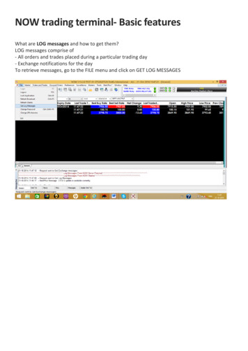
IND560 Installation ManualModel IdentificationThe IND560 model number is located on the data plate on the back of the terminalalong with the serial number. Refer to Figure 1-1 to verify the IND560 that wasordered.Model IND560Enclosure/Display TypeScaleAlways 000Ethernet/Serial portsLocal I/OConnectivity OptionApplication SoftwareModuleLine Cord, PlugRegion/Language/ Character56H40000BPF0B0000 – English,Spanish, French,German, andItalian0 - Panel enclosure, 100 - 240 VAC, no plugA - 120 VAC, US PlugB - 230 VAC, Schuko PlugC - 240 VAC, UK PlugD - 240 VAC, Australian PlugE - 230 VAC, Swiss PlugF - 230 VAC, Danish PlusG - 220 VAC, US PlugH - 230 VAC, India Plug0 - No Module0 - Basic FunctionalityF - Fill-5600 - NoneA - Analog outputB - A-B Remote I/OP - Profibus (panel enclosure)R - Profibus (harsh enclosure)0 - NoneB - Local Discrete I/O, Relay0 - NoneA – Ethernet/Dual Serial Ports0- None1 - Single ALC, Standard4 - IDNet StandardH - Harsh, Graphic VFDP - Panel, Graphic VFDFigure 1-1: IND560 Model Identification Numbers1-4
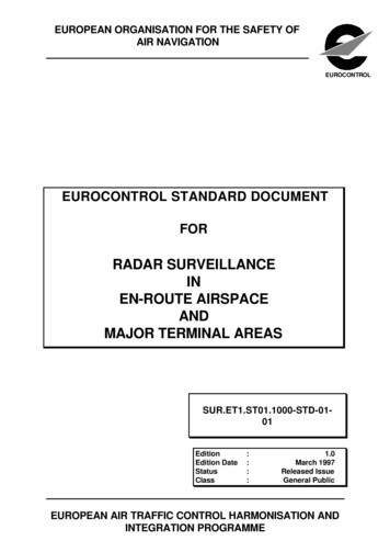
IND560 Installation ManualEnglishPhysical DimensionsThe IND560 terminal physical dimensions for the panel-mount enclosure areshown in Figure 1-2 in inches and [mm].Figure 1-2: IND560 Panel-Mount Enclosure DimensionsThe IND560 terminal physical dimensions for the panel cutout are shown in Figure1-3 in inches and [mm].Figure 1-3: IND560 Panel-Mount Cutout Dimensions1-5
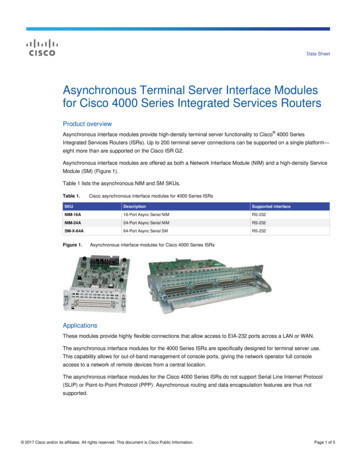
IND560 Installation ManualThe IND560 terminal physical dimensions for the harsh desk/wall-mount enclosureare shown in Figure 1-4 in inches and [mm].Desk-MountWall-Mount(with optional brackets)Figure 1-4: IND560 Harsh Desk/ Enclosure Dimensions1-6
IND560 Installation ManualEnglishSpecificationsThe IND560 terminal conforms to the specifications listed in Table 1-2.Table 1-2: IND560 SpecificationsIND560 SpecificationsEnclosure TypePanel-mount stainless steel front panel with analuminum frameHarsh environment desk/wall/column-mount type 304Lstainless steel enclosureDimensions (l w d)Panel Mount: 265 mm 160 mm 92 mm(10.4 in. 6.3 in. 3.6 in.)Harsh Environment: 265 mm 160 mm 170 mm(10.4 in. 6.3 in. 6.7 in.)Shipping Weight3.5 kg (8 lb)Environmental ProtectionPanel-mount front panel sealing provides type 4 andtype 12 protection—comparable to IP65 rating (ULapproval pending).Harsh Environment meets IP69K requirements (ULapproval pending)Operating EnvironmentThe terminal (both enclosure types) can be operated attemperatures ranging from 10 to 40 C (14 to 104 F) at 10% to 95% relative humidity non-condensing.Hazardous AreasNot all versions of the IND560 can be operated in areasclassified as Hazardous by the National Electrical Code(NEC) because of the combustible or explosiveatmospheres in those areas. Contact an authorizedMETTLER TOLEDO representative for information abouthazardous applications.PowerOperates at 85–264 VAC, 49–61 Hz, 750 mA (bothenclosure types).Panel-mount version provides a terminal strip for ACpower connections.Harsh environment version includes a power cordconfigured for the country of use.Display128 64 dot-matrix graphic VFD display, 21 mmDisplay Update Rate: 10/secondWeight DisplayDisplayed resolution of 100,000 counts for analog loadcell scalesDisplay resolution for high-precision IDNet bases isdetermined by the specific base used1-7
IND560 Installation ManualIND560 SpecificationsScale TypesAnalog load cells orIDNet, High-Precision K Line (T-Brick type standard)Number of CellsEight 350-ohm load cells (2 or 3 mv/V)Number of ScalesInterface for one analog or one IDNet scaleAnalog/Digital Update RatesInternal: Analog: 366 Hz; IDNet: determined by base;Target Comparison: 50 Hz;PLC Interface: 20 HzLoad Cell Excitation Voltage10 VDCMinimum Sensitivity0.1 microvoltsKeypad25 keys; 1.22-mm thick polyester overlay (PET) withpolycarbonate display lensCommunicationsSerial InterfacesStandard: One serial port (COM1)RS-232/RS-422/RS-485, 300 to 115,200 baudOptional Ethernet/Serial Ports: Ethernet 10 Base-T withtwo additional serial ports (COM2 and COM3)ProtocolSerial Inputs: ASCII characters, ASCII commands forCTPZ (Clear, Tare, Print, Zero), SICS (most level 0 andlevel 1 commands)Serial Outputs: Continuous or Demand with up to fiveconfigurable print templates or SICS host protocol, reportprinting, interfaces with external ARM100 Input/Outputmodules and DeviceNet BridgeApprovalsWeights and MeasuresUSA: NTEP Class II, 100,000 d; Class III/IIIL,10,000 d, CoC #05-057Canada: Class III, 10,000 d, approval pendingEurope: OIML; Class II, III, 7,500 e, TC 6812Product SafetyUL, cUL, CEMain PCBThe IND560 terminal’s main printed circuit board (PCB) provides the scaleinterface for analog load cell or IDNet.The main board also contains the COM1 serial port that provides RS-232, RS-422,or RS-485 communication. The port is bidirectional and can be configured forvarious functions such as demand output, SICS host communications, continuousoutput, ASCII command input (C, T, P, Z), ASCII character input, report printing,totals printing, or connection to a remote ARM100 module.The main board also contains the AC power input connections, keyboard interfaceand bus connectors for the option boards.1-8
IND560 Installation ManualScale BasesEnglishThe IND560 supports two types of scale bases: Analog or IDNet.Analog Load Cell Scale BaseThe IND560 supports this scale type by an analog load cell interface. The terminalcan drive up to eight 350-ohm analog load cells.IDNet Scale BaseThe IND560 supports the newer T-brick style of high-precision base through themain board IDNet port. This port provides the 12 volts and communicationrequired to operate this newer style base. The older K module and Pik-brick cellsrequire the addition of an adapter board and new power supply (to support the 32 volt requirement) to the IND560. The adapter board and power supply areavailable as an option.OptionsThe following options are available for the IND560: Discrete I/O–Internal, high-level discrete I/O (4 inputs and 6 outputs)–Remote discrete I/O via ARM100 module Ethernet/Dual Serial Ports Programmable Logic Control (PLC) interfaces, including:–Analog Output–Allen-Bradley (A-B) RIO–PROFIBUS L2DP Fill-560 (application software) Installation kit for older pre-2003 high-precision bases using a Pik-Brick weigh cell InSite Configuration Tool Various brackets for wall and column mounting of the harsh enclosureDiscrete I/OThe discrete I/O interface options include both internal and remote I/O. The internal version is available with dry-contact relay outputs. The relaycontacts will switch up to 30 volts DC or 250 volts AC. The inputs are switchselectable as either active (for simple pushbutton control) or passive (forconnection to PLCs or other devices that supply their own power for the I/O).1-9
IND560 Installation Manual The remote I/O is supported with the ARM100 remote module that providesdry-contact outputs. The inputs are passive on the ARM100. An external24-volt DC supply is required to operate the ARM100. A total of 12 inputs and 18 outputs are supported through a maximum of threeoptions.Ethernet/Serial PortsThe Ethernet port can be used for FTP transfer of tare and target tables andcomplete setup files. It also provides a TCP/IP port to transmit a demand templateor continuous data for remote configuration using the METTLER TOLEDO InSite program, and for direct access to data via a shared data server.COM2 provides RS-232 communication at rates from 300 to 115.2k baud. COM 3supports the same baud rates and provides an RS-232, RS-422, or RS-485connection.PLC InterfacesThe IND560 PLC interface options include Analog Output, A-B RIO, and PROFIBUSL2DP.Analog OutputAnalog Output refers to the representation of an internal system variable using aproportional electrical signal. Analog Output can be used to transmit a measuredvalue, such as the gross or net weight. Another use for Analog Output is as acontrol signal for some external device, such as a control valve, where the amountof valve opening is proportional to the analog signal commanding its operation.Such outputs are used to control the flow rate of material into or out of a vessel.Both 0-10 volt DC and 4-20 mA signals are provided.A-B RIOThe A-B RIO option enables data exchange by bi-dire
latest in METTLER TOLEDO technology and the most versatile weighing terminal available today. The IND560 terminal is a high-performance single- or multiple-range weighing terminal for use with analog load cells or high-precision IDNet scale interfaces used in industrial automation applications.File Size: 1MB