Transcription
IND560TerminalPLC Interface Manualwww.mt.com72184339(05/2009).R05
METTLER TOLEDO 2009No part of this manual may be reproduced or transmitted in any form or by anymeans, electronic or mechanical, including photocopying and recording, for anypurpose without the express written permission of METTLER TOLEDO.U.S. Government Restricted Rights: This documentation is furnished withRestricted Rights.Copyright 2009 METTLER TOLEDO. This documentation contains proprietaryinformation of METTLER TOLEDO. It may not be copied in whole or in partwithout the express written consent of METTLER TOLEDO.METTLER TOLEDO reserves the right to make refinements or changes to theproduct or manual without notice.COPYRIGHTMETTLER TOLEDO is a registered trademark of Mettler-Toledo, Inc. All otherbrand or product names are trademarks or registered trademarks of theirrespective companies.METTLER TOLEDO RESERVES THE RIGHT TO MAKE REFINEMENTS ORCHANGES WITHOUT NOTICE.FCC NoticeThis device complies with Part 15 of the FCC Rules and the Radio InterferenceRequirements of the Canadian Department of Communications. Operation issubject to the following conditions: (1) this device may not cause harmfulinterference, and (2) this device must accept any interference received, includinginterference that may cause undesired operation.This equipment has been tested and found to comply with the limits for a ClassA digital device, pursuant to Part 15 of FCC Rules. These limits are designed toprovide reasonable protection against harmful interference when the equipmentis operated in a commercial environment. This equipment generates, uses, andcan radiate radio frequency energy and, if not installed and used in accordancewith the instruction manual, may cause harmful interference to radiocommunications. Operation of this equipment in a residential area is likely tocause harmful interference in which case the user will be required to correct theinterference at his or her expense.Declaration of Conformity is located on the documentation CD.
CUSTOMER FEEDBACKYour feedback is important to us! If you have a problem with this product or its documentation, or a suggestion on how we canserve you better, please fill out and send this form to us. Or, send your feedback via email to: quality feedback.mtwt@mt.com. Ifyou are in the United States, you can mail this postpaid form to the address on the reverse side or fax it to (614) 438-4355. If youare outside the United States, please apply the appropriate amount of postage before mailing.Your Name:Organization Name:Address:Phone Number: ( )E-mail Address:Fax Number: ( )Date:METTLER TOLEDO Order Number:Part / Product Name:Part / Model Number:Serial Number:Company Name for Installation:Contact Name:Phone Number:Please check the appropriate box to indicate how well this product met your expectations in its intended use?Met and exceeded my needsMet all needsMet most needsMet some needsDid not meet my needsComments/Questions:DO NOT WRITE IN SPACE BELOW; FOR METTLER TOLEDO USE ONLYRetailLight IndustrialRESPONSE: Include Root Cause Analysis and Corrective Action Taken.Heavy IndustrialCustom
FOLD THIS FLAP FIRSTNO POSTAGENECESSARYIF MAILED IN THEUNITED STATESBUSINESS REPLY MAILFIRST CLASSPERMIT NO. 414COLUMBUS, OHPOSTAGE WILL BE PAID BY ADDRESSEEMettler-Toledo, Inc.Quality Manager - MTWTP.O. Box 1705Columbus, OH 43216USAPlease seal with tape
PRECAUTIONS READ this manual BEFORE operating or servicing this equipment and FOLLOWthese instructions carefully. SAVE this manual for future reference.WARNING!FOR CONTINUED PROTECTION AGAINST SHOCK HAZARD CONNECT TOPROPERLY GROUNDED OUTLET ONLY. DO NOT REMOVE THE GROUNDPRONG.WARNING!NOT ALL VERSIONS OF THE IND560 ARE DESIGNED FOR USE INHAZARDOUS (EXPLOSIVE) AREAS. REFER TO THE DATA PLATE OF THEIND560 TO DETERMINE IF A SPECIFIC TERMINAL IS APPROVED FOR USEIN AN AREA CLASSIFIED AS HAZARDOUS BECAUSE OF COMBUSTIBLE OREXPLOSIVE ATMOSPHERES.WARNING!WHEN THIS EQUIPMENT IS INCLUDED AS A COMPONENT PART OF ASYSTEM, THE RESULTING DESIGN MUST BE REVIEWED BY QUALIFIEDPERSONNEL WHO ARE FAMILIAR WITH THE CONSTRUCTION ANDOPERATION OF ALL COMPONENTS IN THE SYSTEM AND THE POTENTIALHAZARDS INVOLVED. FAILURE TO OBSERVE THIS PRECAUTION COULDRESULT IN BODILY HARM AND/OR PROPERTY DAMAGE.CAUTIONBEFORE CONNECTING/DISCONNECTING ANY INTERNAL ELECTRONIC COMPONENTS ORINTERCONNECTING WIRING BETWEEN ELECTRONIC EQUIPMENT ALWAYS REMOVE POWERAND WAIT AT LEAST THIRTY (30) SECONDS BEFORE ANY CONNECTIONS ORDISCONNECTIONS ARE MADE. FAILURE TO OBSERVE THESE PRECAUTIONS COULD RESULTIN DAMAGE TO OR DESTRUCTION OF THE EQUIPMENT AND/OR BODILY HARM.CAUTIONOBSERVE PRECAUTIONS FOR HANDLING ELECTROSTATIC SENSITIVE DEVICES.
IND560TerminalEssential Services for Dependable Performance of Your IND9R86 ControllerCongratulations on choosing the quality and precision of METTLER TOLEDO.Proper use of your new equipment according to this Manual and regular calibrationand maintenance by our factory-trained service team ensures dependable andaccurate operation, protecting your investment. Contact us about a ServiceXXLagreement tailored to your needs and budget. Further information is available atwww.mt.com/serviceXXL.There are several important ways to ensure you maximize the performance of yourinvestment:1. Register your product: We invite you to register your product atwww.mt.com/productregistration so we can contact you about enhancements,updates and important notifications concerning your product.2. Contact METTLER TOLEDO for service: The value of a measurement isproportional to its accuracy – an out of specification scale can diminishquality, reduce profits and increase liability. Timely service from METTLERTOLEDO will ensure accuracy and optimize uptime and equipment life.a. Installation, Configuration, Integration and Training: Our servicerepresentatives are factory-trained, weighing equipment experts. Wemake certain that your weighing equipment is ready for production in acost effective and timely fashion and that personnel are trained forsuccess.b. Initial Calibration Documentation: The installation environment andapplication requirements are unique for every industrial scale soperformance must be tested and certified. Our calibration services andcertificates document accuracy to ensure production quality andprovide a quality system record of performance.c. Periodic Calibration Maintenance: A Calibration Service Agreementprovides on-going confidence in your weighing process anddocumentation of compliance with requirements. We offer a variety ofservice plans that are scheduled to meet your needs and designed to fityour budget.
ContentsChapter 1.0 Analog Output Kit Option .1-1Specifications.1-1Analog Output Operation.1-2Installation.1-4Setup in the IND560 Terminal .1-5Analog Output Setup Sub-Block . 1-5Wiring.1-7Analog Output Kit Spare Parts .1-8Chapter 2.0 A-B RIO Interface .2-1Overview .2-1Communications . 2-2Node/Rack Address. 2-2Data Formats . 2-2Data Definition .2-3Data Integrity. 2-3Discrete Data . 2-3Byte Order. 2-4Message Slots. 2-5Integer and Division . 2-8Floating Point. 2-9Block Transfer . 2-10Block Transfer Formats. 2-11Controlling the Discrete I/O Using a PLC Interface . 2-14Hardware Setup.2-14Wiring . 2-14Software Setup .2-15A-B RIO Setup Sub-Block . 2-15Troubleshooting.2-16Status LEDs . 2-16Allen-Bradley RIO Interface Kit Part Numbers .2-17Interfacing Examples.2-18Chapter 3.0 DeviceNet Interface .3-1Preface.3-1Overview .3-1DeviceNet Characteristics.3-1Communications . 3-3
IND560 PLC Interface ManualNode Address. 3-3Data Formats . 3-3Data Definition .3-3Data Integrity. 3-3Data Formats . 3-3Byte Order. 3-5Message Slots. 3-5Floating Point.3-7Operational Overview . 3-7Floating Point Data Format and Compatibility. 3-8Controlling the Discrete I/O Using a PLC Interface . 3-9Hardware Setup.3-9Wiring . 3-9Software Setup .3-9DeviceNet Setup Blocks . 3-10Troubleshooting.3-10DeviceNet Option Kit .3-11DeviceNet Commissioning and Configuration Examples .3-12Configuring the IND560 Terminal with RSNetWorx for DeviceNet . 3-12PLC Programming . 3-23 Chapter 4.0 PROFIBUS Interface.4-1Overview .4-1Communications . 4-2Node/Rack Address. 4-4Data Formats . 4-4Data Integrity .4-5Discrete Data .4-5Byte Order. 4-6Floating Point.4-7Floating Point Numbers . 4-8Shared Data.4-9Discrete Data I/O Space Usage Comparison .4-10IND560 PROFIBUS Message Mapping.4-13Controlling Discrete I/O Using a PLC Interface.4-18Hardware Setup.4-18Wiring . 4-18Software Setup .4-19PROFIBUS Setup Sub-Block. 4-19PROFIBUS GSD or Type Files. 4-19
IND560 PLC Interface ManualPROFIBUS Option Kit Part Numbers.4-20Interfacing Examples.4-21Chapter 5.0 EtherNet/IP Interface.5-1Overview .5-1Definition of Terms. 5-2Communications . 5-4IP Address . 5-4Data Formats . 5-4Data Definition .5-4Data Integrity. 5-5Assembly Instances of Class 1 Cyclic Communications. 5-5Discrete Data . 5-5Byte Order. 5-6Message Slots. 5-7Controlling the Discrete I/O Using a PLC Interface . 5-10Software Setup .5-10EtherNet/IP Setup Block . 5-11Troubleshooting.5-11Status LEDs . 5-12EtherNet/IP Option Kit .5-12Programming Examples .5-13Chapter 6.0 Modbus TCP Interface .6-1Preface.6-1Overview .6-1Specifications. 6-1Modbus TCP Characteristics.6-2Modbus TCP Board.6-2Communications . 6-2IP Address . 6-3Data Formats . 6-3Data Definition .6-3Data Integrity. 6-3Discrete Data . 6-3Byte Order. 6-5Register Mapping. 6-5Message Slots. 6-6Integer and Division . 6-9Floating Point. 6-9Controlling the Discrete I/O Using a PLC Interface . 6-10
IND560 PLC Interface ManualSoftware Setup .6-11Modbus TCP Setup Block. 6-11Troubleshooting.6-12Status LEDs . 6-12Modbus TCP Option Kit .6-13Modbus TCP Configuration Example .6-13Integer Logic Examples . 6-19Appendix AAppendix BInteger and Division Data Formats. A-1Floating Point Data Format .B-1Operational Overview .B-1Appendix CASCII Characters.C-1Standard Characters.C-1Control Characters .C-2
Chapter 1.0Analog Output Kit OptionThe Analog Output option kit provides an isolated 4-20 mA or 0-10 VDC analogsignal output for displayed weight, gross weight or rate (if enabled in setup). Theanalog output uses a 16-bit D/A converter for a very precise output. The outputsignals will be at the lower limit (0 VDC or 4 mA) when the value represented is atzero. When the value reaches its maximum limit, the output signal will increase tohigher limit (10 VDC or 20 mA). Any value between zero and the maximum limitwill be represented as a percentage of the output proportional to the percentage ofthe value.The Analog Output sub-block lets you select the data source for the analog signaland provides a method to calibrate the analog zero and high limit values. TheIND560 terminal must be calibrated to the desired scale capacity before makingAnalog Output adjustments. If rate is to be used as the source for the analog outputsignal, it must be enabled in the Scale Rate branch of setup. The Analog Outputcard provides one channel - it may be either current (4-20 mA) or voltage (0-10VDC).SpecificationsMaximum Cable Length:0-10 VDC – 50 ft (15.2 m)4-20mA – 1000 ft (300 m)Min/Max Load Resistance:0-10 VDC – 100k ohms minimum4-20 mA – 500 ohms maximumOutputs:1 channel capable of supplying 4-20 mA or 0-10 VDCResolution:16 bit resolution - 65536 levels across entire rangeNote that if the load resistance ratings are exceeded, the analog output will notoperate properly.1-1
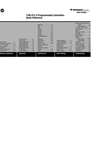
IND560 PLC Interface ManualFigure 1-1 shows an Analog Output Option Board with its connector at bottomcenter.Figure 1-1
Contact METTLER TOLEDO for service: The value of a measurement is proportional to its accuracy – an out of specification scale can diminish quality, reduce profits and increase liability. Timely service from METTLER TOLEDO will ensure accuracy and optimize uptime and equipment life.