Transcription
InstallationManual InstallationStartupMaintenancePartsNOTICEWhen installing Modelsmanufactured after July7th, 2008, you will noticeadditional selections onthe Installer Menu of theControl that will notapply to this unit. DONOT CHANGE THESEFACTORY SETTINGS.Refer to the ControlProgram Reference Chartwithin this manual forselections that apply tothis model.MH18082WARNINGThis manual must only be used by a qualified heating installer/service technician. Read all instructionsin this manual before installing. Perform steps in the order given. Failure to comply could result insevere personal injury, death or substantial property damage.
GAS-FIRED HEATERInstallation ManualWARNINGIf the information in this manual is not followed exactly, a fire or explosion may result causing property damage,personal injury or loss of life.Do not store or use gasoline or other flammable vapors and liquids in the vicinity of this or any other appliance.WHAT TO DO IF YOU SMELL GAS 1Do not try to light any appliance.Do not touch any electrical switch: do not useany phone in your building.Immediately call your gas supplier from aneighbor's phone. Follow the gas supplier'sinstructions. If you cannot reach your gas supplier, call the firedepartment. Installation and service must beperformed by a qualified installer, service agency orthe gas supplier.Installation and service must performed by aqualified installer, service agency or the gas supplier.
GAS-FIRED HEATERInstallation ManualCONTENTSPart 1 – Product and Safety Information. . . . . . . . . . . . . . . . . . . . . . . . . . . . . . . . . . . . . . 4,5Part 2 – How The Heater Operates. . . . . . . . . . . . . . . . . . . . . . . . . . . . . . . . . . . . . . . . . . . 6-8Part 3 – Prepare Heater Location . . . . . . . . . . . . . . . . . . . . . . . . . . . . . . . . . . . . . . . . . . . 8-11A.B.C.D.E.F.G.Installations Must Comply With:Before Locating HeaterClearances for Service AccessResidential Garage InstallationAir Intake and Exhaust VentPrevent Combustion Air ContaminationWhen Removing an Appliance from an Existing Common Vent SystemPart 4 – Prepare Munchkin Contender Heater . . . . . . . . . . . . . . . . . . . . . . . . . . . . . . . 11-12A.B.C.D.Remove Munchkin Contender Heater from BoxPlacing Wall-Mounted Munchkin ContenderMunchkin Contender Wall Mounting InstructionInstallation StepsPart 5 – Munchkin Contender Piping . . . . . . . . . . . . . . . . . . . . . . . . . . . . . . . . . . . . . . . 13-24– Contender Piping Details . . . . . . . . . . . . . . . . . . . . . . . . . . . . . . . . . . . . . . . . . . . . 18-24A.B.C.D.E.F.G.H.I.J.K.L.M.Relief ValveGeneral Piping InformationSeparate Low Water CutoffBackflow PreventerSystem Water Piping MethodsCirculatorsHydronic Piping with Circulators, Zone Valves and Multiple HeatersCirculator SizingFill and Purge Heating SystemZoning with Zone ValvesZoning with CirculatorsMultiple HeatersContender Piping DetailsPart 6 – Contender Piping with Optional Vision 1 System . . . . . . . . . . . . . . . . . . . . . 25-35– Contender Piping Details With Vision I System . . . . . . . . . . . . . . . . . . . . . . . . . . 26-35A.B.C.D.Vision 1 System PipingZoning with Zone Valves Using Vision IZoning with Circulators Using Vision IContender Piping Details with the Vision I SystemPart 7 – Venting Combustion Air And Condensate Removal. . . . . . . . . . . . . . . . . . . . 36-44– Venting Details . . . . . . . . . . . . . . . . . . . . . . . . . . . . . . . . . . . . . . . . . . . . . . . . . . . . . 43,44A.B.C.D.E.Installing Exhaust Vent and Intake Air VentGeneralApproved Materials for Exhaust Vent and Intake Air VentExhaust Vent and Intake Air Vent Pipe Location.Exhaust Vent and Intake Air Vent Sizing2
GAS-FIRED HEATERInstallation ManualCONTENTS (CONT’D)F.G.H.I.Exhaust Vent and Intake Air Pipe Installation.Heater Removal from a Common Vent SystemCondensate Removal SystemDiagrams for Side Wall VentingPart 8 – Gas Piping . . . . . . . . . . . . . . . . . . . . . . . . . . . . . . . . . . . . . . . . . . . . . . . . . . . . . . 45,46A.B.C.D.Gas ConnectionGas PipingGas TableDungs Gas ValvePart 9 – Field Wiring. . . . . . . . . . . . . . . . . . . . . . . . . . . . . . . . . . . . . . . . . . . . . . . . . . . . . 47-49A.B.C.D.Installation Must Comply WithField WiringLine Voltage WiringThermostatPart 10 – Field Wiring – Vision 1 Option. . . . . . . . . . . . . . . . . . . . . . . . . . . . . . . . . . . . . . . 50Part 11 – Start Up Preparation . . . . . . . . . . . . . . . . . . . . . . . . . . . . . . . . . . . . . . . . . . . . 51-55A.B.C.D.E.F.G.H.I.Check/Control Water ChemistryFreeze Protection (when used)Fill and Test Water SystemAir Purging Procedure; Munchkin Contender Heat ExchangerPurge Air from Water SystemCheck for Gas LeaksCheck Thermostat Circuit(s)Condensate RemovalFinal Checks Before Starting The Munchkin ContenderPart 12 – Start-Up Procedure . . . . . . . . . . . . . . . . . . . . . . . . . . . . . . . . . . . . . . . . . . . . . 55-57A.B.C.D.Operating InstructionsAdjusting the Set PointStatus MenuTest ModePart 13 – Start-Up Procedures With The Vision 1 Option . . . . . . . . . . . . . . . . . . . . . . 57-60A. Programming the Vision I OptionB. Vision I Program AccessC. Vision I Program NavigationPart 14 – Troubleshooting. . . . . . . . . . . . . . . . . . . . . . . . . . . . . . . . . . . . . . . . . . . . . . . . 61-64A. Munchkin Error CodeB. Heater ErrorC. Heater FaultPart 15 – Maintenance. . . . . . . . . . . . . . . . . . . . . . . . . . . . . . . . . . . . . . . . . . . . . . . . . . . 64-68A. Maintenance ProceduresB. Combustion Chamber Coil Cleaning InstructionsPart 16 – Heater Inspection and Maintenance Start-Up Charts . . . . . . . . . . . . . . . . . 69-713
GAS-FIRED HEATERInstallation ManualPART 1: PRODUCT AND SAFETY INFORMATIONSPECIAL ATTENTION BOXESThe following defined terms are used throughout this manual to bring attention to the presence ofhazards of various risk levels or to important information concerning the product.DEFINITIONSDANGERDANGER indicates an imminently hazardoussituation which, if not avoided, will result indeath or serious injury.WARNINGWARNING indicates a potentially hazardoussituation which, if not avoided, could result indeath or serious injury.CAUTIONCAUTION Indicates a potentially hazardoussituation which, if not avoided, may result inminor or moderate injury.CAUTIONCAUTION used without the safety alert symbolindicates a potentially hazardous situation which,if not avoided, may result in property damage.NOTICEHeat Transfer Products, Inc., reserves the right to make product changes or updates without noticeand will not be held liable for typographical errors in literature.4
GAS-FIRED HEATERInstallation ManualPART 1: PRODUCT AND SAFETY INFORMATION (CONT’D)supply to circulator. Instead, shut off the gassupply at a location external to the appliance.WARNINGInstaller — Read all instructions in this manual,and Munchkin Contender Venting section,before installing. Perform steps in the ordergiven.User — This manual is for use only by aqualified heating installer/service technician.Refer to User’s Information Manual for yourreference.User — Have this heater serviced/inspected bya qualified service technician annually.Failure to comply with the above could result insevere personal injury, death or substantialproperty damage.WARNINGFailure to adhere to the guidelines on this pagecan result in severe personal injury, death orsubstantial property damage. Do not use this heater if any part has beenunder water. Immediately call a qualifiedservice technician to inspect the heater andto replace any part of the control system andany gas control that has been under water.HEATER WATERThe piping and components connected to theMunchkin Contender for space the heatingapplication shall be suitable for use with potablewater. Toxic chemicals, such a used for boilertreatment, shall not be introduced into thepotable water when the Munckin Contender isused for space heating.When the Munchkin Contender is used to supply potable water, it shall not be connected toany heating system or component(s) previouslyused with a non-potable water heating appliance.WARNINGWARNINGWHAT TO DO IF YOU SMELL GAS Do not try to light any appliance. Do not touch any electric switch; do not useany phone in your building. Immediately call your gas supplier from aneighbor's phone. Follow the gas suppliers'instructions. If you cannot reach your gas supplier, call thefire department.NEVER use any toxic chemical, includingautomotive or standard glycol antifreeze orethylene glycol made for hydronic (non-potable)systems. These chemicals are poisonous ifconsumed and can cause injury or death. Thesechemicals can also attack gaskets and seals inwater heaters. If you have an old system with cast ironradiators, thoroughly flush the system (withoutheater connected) to remove sediment. Thehigh-efficiency heat exchanger can be damagedby build-up or corrosion due to sediment. Do not use petroleum-based cleaning or sealingcompounds in heater system. Gaskets and sealsin the system may be damaged. This can resultin substantial property damage. Do not use “homemade cures” or “boiler patentmedicines.” Substantial property damage,damage to heater, and/or serious personal injurymay result. Continual fresh make-up water will reduce theheater life. Mineral buildup in heat exchangerreduces heat transfer, overheats the stainlesssteel heat exchanger, and causes failure.Addition of oxygen carried in by make-up waterBefore InstallingWHEN SERVICING THE MUNCHKIN CONTENDER To avoid electric shock, disconnect electricalsupply before performing maintenance. To avoid severe burns, allow heater to coolbefore performing maintenance.MUNCHKIN CONTENDER OPERATION Do not block flow of combustion orventilation air to heater. Should overheating occur or gas supply fail toshut off, do not turn off or disconnect electrical5
GAS-FIRED HEATERInstallation ManualPART 1: PRODUCT AND SAFETY INFORMATION (CONT’Dcan cause internal corrosion in systemcomponents. Leaks in heater or piping must berepaired at once to prevent make-up water.WINTERIZING THE MUNCHKIN CONTENDERTo winterize the Munchkin Contender, drain theentire system, then apply air pressure to thedrain valve and allow air and water to escapefrom the purge valve (see piping instructions).Once you have evacuated all of the water that ispossible, you will then need to pump in the nontoxic propylene glycol food grade NSF listedantifreeze (SAFE-T-THERM www.houghton.comor PARATHERM www.paratherm.com). Try tocalculate the entire volume of the piping systemto insure the entire system will be adequatelyprotected. Consult the glycol manufacturer formixture % recommendations to adequately protect the system for the local climate of the installation.With a pump, fill the system with the non-toxicpropylene glycol food grade NSF listedantifreeze, allowing the air and remaining waterto escape from the purge valve. Once thestream coming out of the purge valve matchesthe color of the non toxic propylene glycol foodgrade NSF listed antifreeze, the system shouldbe adequately filled. It is rcommended at thispoint to start any circulation pump and allow thesystem to circulate for at least 30 minutes tocompletely blend any trapped water that mightbe in the system with the NSF listed solution.At this point it is suggested that you check theconcentration of NSF antifreeze to be sure thatprotection is adequate. Consult the glycol manufacturer for specific instructions on the concentration % as well as the freeze and burst protection methods.FREEZE PROTECTION FLUIDSCAUTIONNEVER use automotive or standard glycolantifreeze, even ethylene glycol made forhydronic systems. Use only inhibited propyleneglycol solutions, which are specificallyformulated for hydronic systems. Ethyleneglycol is toxic and can attack gaskets and sealsused in hydronic systems.CAUTIONConsider piping and installation whendetermining heater location. Any claims fordamage or shortage in shipment must be filedimmediately against the transportationcompany by the consignee.PART 2: HOW THE MUNCKIN CONTENDER OPERATESMunchkin Contender Condensing Technology isan intelligent system that delivers highly efficienthydronic heating, while maximizing efficiency bymeasuring the Data Parameters of your heatingsystem.1. Stainless Steel Heat ExchangerThe highly efficient durable MunchkinContender Stainless Steel Heat Exchanger isdesigned to take the colder return water fromthe system and extract the last bit of energybefore it is exhausted. The heat exchangerdesign is separated by an internal baffle whichdiverts the exhaust gas through the primaryheat exchanger into the secondary heatexchanger where the colder return waterextracts the last residual heat.2. Modulating Combustion SystemModulation during the central heatingoperation is based on the supply temperature.The set point used for the control dependsupon the programmed central heating curve.The slope of the heating curve can be changedby the installer of the Munchkin Contender inthe sense that both turning points of the curvecan be moved. The control monitors thesystem to regulate the output of the burnerduring operation to match the systemdemand. This increase in efficiency allows forsubstantial fuel savings.3. Gas ValveThe gas valve senses suction from the blower,allowing gas to flow only if the gas valve is6
GAS-FIRED HEATERInstallation ManualPART 2: HOW THE MUNCHKIN CONTENDER OPERATES (CONT’D)powered and combustion air is flowing.4. Swirl Plate SystemThe Swirl Plate on the gas valve controls theair and gas flow into the burner, which willassure better mixing for improvedcombustion.5. Supply water temperature sensorThis sensor monitors heater output watertemperature (system supply). The controlmodule adjusts the heater firing rate so theoutlet temperature is correct.6. Return water temperature sensorThis sensor monitors the return watertemperature (system return). The controlmodule reduces or increases heater input,depending on how close the return watertemperature is to the outlet watertemperature.7. Temperature and pressure gaugeAllows the user to monitor the systemstemperature and pressure.8. ControlThe integrated control system monitors thereturn and supply water and regulates the fanspeed to regulate the unit’s BTU output. Thisallows the unit to only deliver the amount ofheated energy required and nothing more!9. Flue pipe adapterThe flue pipe adapter may be positioned sothat the installer is able to find a position thatwill best facilitate the exhaust and combustionair pipe connections with the least number ofelbows even in the most challengingapplications.10. BurnerMade with metal fiber and stainless steelconstruction, the burner uses pre-mixed airand gas and provides a wide range of firingrates.11. Electrical field connections with terminal stripsThe electrical cover plate allows access theline voltage terminal strip and the low voltageterminal strip. Attach line voltage conduits tothe three holes at the right of the line voltageterminal strip for power, CH pump and DHW7pump. Route low voltage wires through theopening to the left of the low voltage terminalstrip. (See Field Wiring Instructions Part 9.)12. Condensate drain connectionThis is a condensing high efficiency appliance,therefore this unit has a condensate removalsystem. Condensate is nothing more thanwater vapor, derived from the combustionproducts, similar to an automobile when it isinitially started. It is very important that thecondensate line is sloped away from theheater and down to a suitable inside drain, ifthe condensate outlet on the MunchkinContender is lower than the drain, you mustuse a condensate removal pump (kit p/n554200 available from Heat Transfer Products,Inc.) A condensate filter, if required by localauthorities can be made up of lime crystals,marble or phosphate chips and will neutralizethe condensate. This can be done in the fieldby the installer or you may purchase one fromHeat Transfer Products, Inc. (P/N N1100). It isalso very important that the condensate line isnot exposed to freezing temperatures or anyother type of blockage. Plastic tubing shouldbe the only material used for the condensateline. Steel, brass, copper or others will besubject to corrosion or deterioration. A secondvent may be necessary to prevent condensateline vacuum lock if a long horizontal run isused. Also, an increase in pipe size may benecessary to drain properly. Support of thecondensation line may be necessary to avoidblockage of the condensate flow.13. Spark ignitionThe burner flame is ignited by applying a highvoltage to the system spark electrode. Thiscauses a spark from electrode to ground.14. The Vision 1 Optional SystemThe Vision I System will allow the installingcontractor to take the highly efficientmodulating Munchkin Contender and make iteven more efficient by controlling thetemperature delivered to the central heatingcircuits based on the outside temperature. TheVision I system is also a two temperaturesystem, one temperature for central heatingand the other temperature to the Super StorUltra Indirect water heater. This allows the userto increase the temperature supplied to the
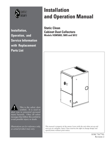
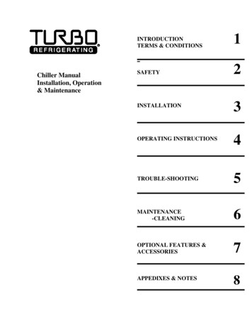
Installation ManualGAS-FIRED HEATERPART 2: HOW THE MUNCHKIN CONTENDER OPERATES (CONT’D)Super Stor Ultra Indirect Water Heater to get afast recovery by prioritizing the flow at a highertemperature than may be needed for thecentral heating circuits (this will require twoseparate circulators). You must follow thepiping, wiring and programming instructionslocated in the Vision One section of thismanual. Optional kit consists of the following Outdoor sensor – 7250P-319 Indirect tank sensor – 7250P-3251SYSTEM RETURN4COMBUSTION AIR INLET CONNECTION7ELECTRICAL BOX/CONTROL PANEL2SYSTEM SUPPLY5EXHAUST VENT CONNECTION8GAS LINE CONNECTION6CONDENSATE CUP/DRAIN ASSEMBLY3SYSTEM RELIEFA5GHM4NJBCO71DE8SQKL3P6R2FLEFT SIDEVIEWRIGHT SIDEVIEWFRONT VIEWBACK VIEWMUNCHKIN CONTENDER HEATER DIMENSIONS AND SPECIFICATIONSBTU/HR BUT/HRMODEL INPUTINPUTNUMBER LOWHIGHFIREFIRE1.2.ABCDEFGHJKLMNOPQRSCOMBUSTION AIRINLET/EXHAUSTSYSTEMVENTRELIEFCONNECTION PIPE SIZESIZESYSTEM SUPPLY/SYSTEM RETURN/PIPE SIZELOWGASHEATER ENERGY DOE WATERLINEWATER FACTOR EFF.EFF.AFUE 1CONN. VOLUMEEFLTAAE 06.5010.254.002.00.751.25.75.58.9392%98%71 751.25.75.67.9392%98%74 .751.25.75.96.9593%98%84 LBSMC12044,000 120,000 98%84 LBSTested by Heat Transfer Products to the ANSI/ASHRAE 103Tested by Heat Transfer Products to the ANSI/ASHRAE Standard 103 with 90 return and 110 supply waterLP-171-B Rev. 12/3/07PART 3: PREPARE MUNCHKIN CONTENDER LOCATIONA. INSTALLATIONS MUST COMPLY WITH: Local, state, provincial, and national codes,laws, regulations and ordinances. National Fuel Gas Code, ANSI Z223.1 – latestedition. National Electrical Code. For Canada only: B149.1 or B149.2Installation Code, CSA C22.1 CanadianElectrical Code Part 1 and any local codes.8
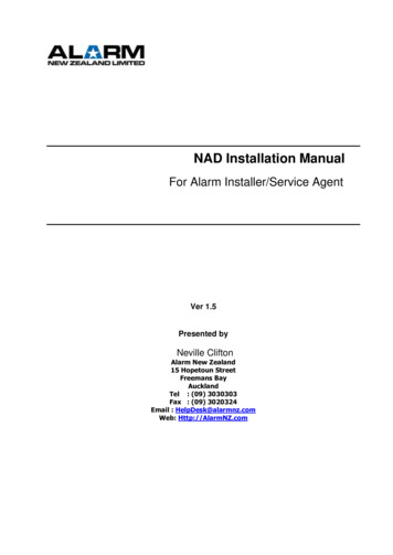
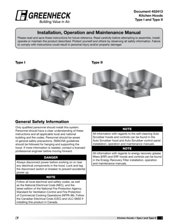
GAS-FIRED HEATERInstallation ManualPART 3: PREPARE MUNCHKIN CONTENDER LOCATION (CONTINUED)NOTICEThe Munchkin Contender Heater gas manifoldand controls met safe lighting and otherperformance criteria when heater underwenttests specified in ANSI Z21.10.3 — latest edition.BEFORE LOCATING THE MUNCHKINCONTENDER1. Check for nearby connection to: System water piping Venting connections Gas supply piping Electrical power24"FRONT CLEARANCE2. Check area around heater. Remove anycombustible materials, gasoline and otherflammable liquids.24"WARNINGFailure to keep heater area clear and f
used for space heating. When the Munchkin Contender is used to sup-ply potable water, it shall not be connected to any heating system or component(s) previously used with a non-potable water heating appli-ance. If you have an old system with cast iron radiators, thoroughly flush the system (without heater connected) to remove sediment. The