Transcription
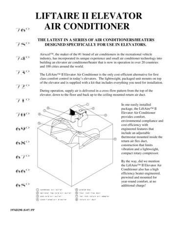
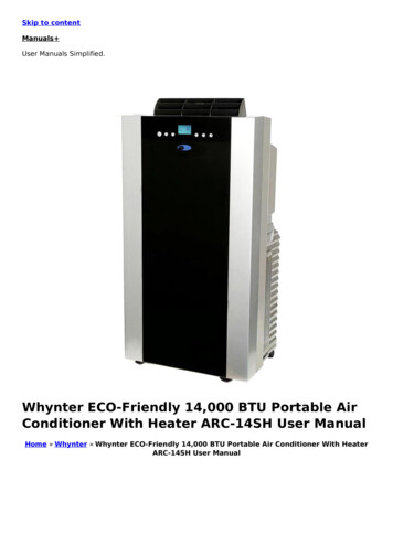
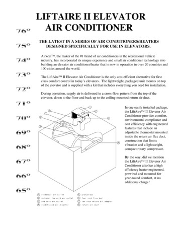
LIFTAIRE II ELEVATORAIR CONDITIONERTHE LATEST IN A SERIES OF AIR CONDITIONERS/HEATERSDESIGNED SPECIFICALLY FOR USE IN ELEVATORS.Airxcel , the maker of the #1 brand of air conditioners in the recreational vehicleindustry, has incorporated its unique experience and small air conditioner technology intobuilding an elevator air conditioner/heater that is now in operation in over 20 countries and100 cities around the world.The LiftAire II Elevator Air Conditioner is the only cost-efficient alternative for firstclass comfort control in today’s elevators. The lightweight, packaged unit mounts on topof the elevator and is supplied with a kit that includes everything you need for installation.During operation, supply air is delivered in a cross-flow pattern from the top of theelevator, down to the floor and back up to the ceiling mounted return air duct.In one easily installed package,the LiftAire II Elevator AirConditioner provides comfort,environmental compliance andcost efficiency with engineeredfeatures that include anadjustable thermostat mountedinside the return air flex duct,construction that limitsvibration and a lightweight,compact rotary compressor.By the way, did we mentionthe LiftAire II Elevator AirConditioner also has a highefficiency heater engineered,prewired and mounted foryear-round comfort, at noadditional charge!
1. WARNINGSWARNING - SHOCK HAZARDIMPORTANT NOTICETo prevent the possibility of severe personal injury orequipment damage due to electrical shock, always be sure theelectrical power source to the appliance is disconnected duringinstallation and service.These instructions are for qualified individuals specially trainedand experienced in installation of this type of electricalequipment and related system components.Installation and service personnel are required by some states tobe licensed. PERSONS NOT QUALIFIED SHALL NOTINSTALL NOR SERVICE THIS EQUIPMENT.CAREFULLY FOLLOW ALL INSTRUCTIONS ANDWARNINGS IN THIS BOOKLET TO AVOID DAMAGE TOTHE EQUIPMENT, PERSONAL INJURY OR FIRE.NOTEWARNINGThe words “Shall” or “Must” indicate a requirement which isessential to satisfactory and safe product performance andinstallation.Improper installation may damage equipment, can create ahazard and voids the warranty.The words “Should” or “May” indicate a recommendation oradvice which is not essential and not required but is useful orhelpful.The use of components not tested in combination with this unitwill void the warranty, may make the equipment in violation ofstate codes, may create a hazard and may ruin the equipment.2. COMPONENT MATCH-UP1.6533-892 (115 V, 60 Hz) or 6573-892(240 V, 50 Hz) Package Air Conditioner2.6533-625 Installation Kit (Included)3. SPECIFICATIONS AND UNIT IDENTIFICATIONSPECIFICATIONSMODEL NO. 6533-892MODEL NO. 6573-892150 PSIG330 PSIG150 PSIG305 PSIGVolts115240Hz6050Phase11Maximum Overcurrent Protective Device20 Amps*15 Amps*Minimum Circuit Ampacity20 Amps*15 Amps*Heater Amps13.310.8BTUH Heating Capacity56008800BTUH Cooling Capacity14,00014,000Fan Motor HP - Amps1/5 - 2.11/5 - 1.0Blower Motor HP - Amps1/5 - 2.41/5 - 1.2Compressor RLA - LRA11.3 - 675.5 - 32R-22 Charge Weight24.0 oz.20.5 oz.Maximum External Static Pressure.80 IN H20.60 IN H20Maximum Outlet Air Temperature161 F. (71.7 C.)178 F. (81.1 C.)0 in.0 in.Design Pressures - Low SideHigh SideMinimum Spacing To Combustible Surface* Air conditioner only. Does not include condensate evaporator.
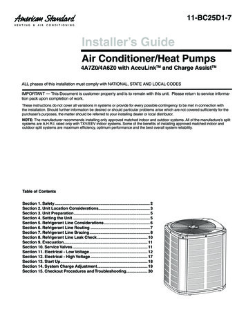
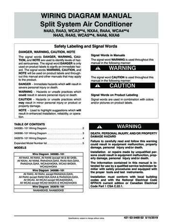
4. UNIT DEPICTION FIGURESFIGURE 1FIGURE 2FIGURE 3
5. GENERAL INFORMATIONThe 6533 (115 volt) and 6573 (240 volt) series package airconditioners are intended for installation on the roof ofelevator cabs or like-sized indoor use contrivances.Installation area should be sufficient to allow proper cutoutsand unit mounting without cutting vital frame members orelectrical wiring. Structural members should not createrestrictions to airway ducts.Recommended installations are shown in Figures 3 & 4.Actual mounting and placement can vary according toexisting conditions.Conditioned air is delivered from the air conditioner to theinterior of the enclosure through ducting that is supplied inInstallation Kit #6533-625 as shown in Figure 2.The system’s return air duct, thermostat, etc. are also foundin the Installation Kit.The air conditioner is powered by a 115 volt, 60 Hz, 1 Phase,20 Amp electrical service for the 6533 series and 240 volt, 50Hz, 1 Phase, 15 Amp electrical service for the 6573 series.6. UNIT INSTALLATIONRefer to Figure 3:1.The air conditioner draws in topside air to cool thecondensing coil. The air is drawn in from the end ofthe air conditioner (across the condensing coil), anddischarged out through the discharge opening.cable. Attach thermostat with mounting bracket to a10-inch collar assembly using two (2) sheet metalscrews.6.Cut a 10 1/8" square opening in the cab top as far aspossible from the intended location of the supply airdistribution scoops. Position 10-inch diameter collarassembly with the thermostat/bracket over theopening. Fasten the collar to the canopy with rivetsor screws. Using quality duct tape, seal the seamsaround the perimeter of the collar assembly.7.Install the four (4) supply air distribution scoops inan area as far as possible from the return air 10-inchdiameter collar assembly installed in Step 6. Airfrom the scoops should have a clear path into theconditioned cab. Attach the scoop with adhesive,straps, brackets or by fastening through the part. Ifattaching with fasteners, pre-drill any clearanceholes in the scoops to prevent cracking duringinstallation. It is also good practice to mount thescoop away from any heat producing devices such aslights, fixtures, etc.8.Attach one (1) 10-inch starting collar by crimpingthe existing tabs and attach four (4) 4-inch startingcollars to the plenum box. Mount the plenum boxbelow the cab top and run the 4 inch plenum supplyair flex duct from the plenum to the four (4) airdistribution scoops. Ensure that the most direct andshortest length of duct is used. Cut off any excess.Secure duct at plenum and scoops using the duct tiesprovided. Cut a 14-inch diameter hole in the cab topfor the 10-inch diameter insulated supply air flexduct to pass through. Connect duct to the top ofplenum and to the collar assembly installed in Step2. Ensure that the most direct and shortest length ofTo provide adequate condensing airflow, theinstaller must adhere to the following guidelines: The air path to the condensing coil shouldbe as direct and non-restrictive as possible. Do not block or restrict the dischargeopening. Ensure that there are no structural membersor panels which would serve to causecondenser discharge air to recirculate intothe condenser return air.2.Remove and discard the plate and styrofoam adapterfrom the desired supply air outlet (top or end).Attach the 10-inch diameter collar assembly usingthe existing screws supplied on top of the airconditioner.3.Mount the 10-inch diameter starting collar to thereturn air inlet by crimping the existing tabs.4.Mount the air conditioner using the four shippingbrackets or use band or brackets of your own. Ifusing a condensate evaporator with the airconditioner, elevate the air conditioner 4-5 inches toensure proper drainage of condensate from the airconditioner drain pan to the evaporator.5.Mount the thermostat to the thermostat mountingbracket using the screws provided with thethermostat. Connect extension cable to thermostats
duct is used. Cut off any excess. Secure the duct atthe plenum and collar assembly using the duct tiesprovided.9.10.11.Plug remaining end of cable to the air conditionersthermostat 4-pin connector.12.Attach the 7/8 inch ID condensate drain hose to thedrain pan on the air conditioner and secure with thehose clamp provided.Connect the 10-inch diameter uninsulated return airflex duct to the return air starting collar installed inStep 3. Secure the duct to the collar assembly usingthe duct ties provided.Determine the most direct and shortest length of ductto be used to connect the 10-inch diameteruninsulated return air flex duct to the 10 inchdiameter collar installed in Step 6. Cut a small slitthrough the 10-inch diameter uninsulated return airflex duct directly above the 10-inch diameter collarassembly and route the thermostat extension cablethrough the slit in the duct. Cut off any excess ductand attach duct to collar using the duct ties provided.Seal the duct where the thermostat cable exits with aquality duct tape.DANGER - SHOCK HAZARDDo not drill any openings into this air conditioner. Whenattaching any collars, ducts or adapters directly to the airconditioner, use only the pilot holes already provided.Drilling new openings and inserting screws may damageeither the refrigeration circuit or electrical wiring,causing possible equipment damage, personal injury ordeath.7. ALTERNATE UNIT INSTALLATIONensure proper drainage of condensate from the airconditioner drain pan to the evaporator.Refer to Figure 4:1.The air conditioner draws topside air to cool thecondensing coil. The air is drawn in from the end ofthe air conditioner, across the condensing coil, anddischarged through the discharge opening. Toprovide adequate condensing airflow, the installermust adhere to the following guidelines: The air path to the condensing coil shouldbe as direct and non-restrictive as possible. Do not block or restrict the dischargeopening. Ensure that there are no panels or structuralmembers that cause the condenser dischargeair to be recirculated into the condenserreturn air.2.Remove and discard the plate and styrofoam adapterfrom the desired supply air outlet (top or end).Attach the 10-inch diameter collar assembly usingthe existing screws supplied on top of the airconditioner.3.Mount the 10-inch diameter starting collar to thereturn air inlet by crimping the existing tabs.4.Mount the air conditioner using the four (4) shippingbrackets or use band or brackets of your own. Ifusing a condensate evaporator with the airconditioner, elevate the air conditioner 4-5 inches to5.Mount the thermostat to the thermostat mountingbracket using the screws provided with thethermostat. Connect extension cable to thermostatcable. Attach thermostat with mounting bracket to a10-inch collar assembly using two (2) sheet metalscrews.6.Cut a 10 1/8 inch square opening in the cab top asfar as possible from the intended location of thesupply air flex duct into the cab. Position 10-inchdiameter collar assembly with the thermostat/bracketover the opening. Fasten the collar to the cab topwith rivets or screws. Using quality duct tape, sealthe seams around the perimeter of the collarassembly.7.Install one (1) supply air distribution diffuser in thecab in an area as far as possible from the return air10-inch diameter collar assembly installed in Step 6.Air from the diffuser should have a clear path intothe conditioned cab. The diffuser used is to beprovided by the installer and should be capable ofusing the 10-inch diameter insulated supply air flexduct. It is also good practice to mount the diffuseraway from any heat producing devices such as lights,fixtures, etc.8.Cut a 14-inch diameter hole in the cab top for the10-inch diameter insulated supply air flex duct topass through. Connect duct to top of diffuser and tothe collar assembly installed in Step 2. Ensure that
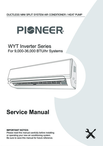
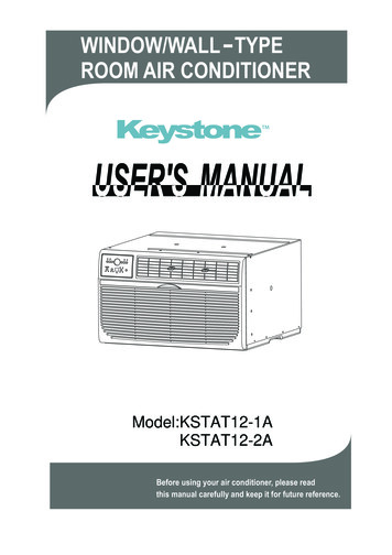
the most direct and shortest length of duct is used.Cut off any excess. Secure the duct at the diffuserand collar assembly using the duct ties provided.9.Connect the 10-inch diameter uninsulated returnair flex duct to the return air starting collarinstalled in Step 3. Secure the duct to thecollar assembly using the duct ties provided.10.Determine the most direct and shortest lengthof duct to be used to connect the 10-inchdiameter uninsulated return air flex duct to the10-inch diameter collar assembly installed in Step 6.Cut a small sli through the 10-inch diameteruninsulated return air flex duct directly above the10-inch diameter collar assembly and route thethermostat extension cable through the slit in theduct. Cut off any excess duct and attach the duct tothe collar using the duct ties provided. Seal the ductwhere the thermostat cable exits with a quality ducttape.11.Plug the remaining end of the cable into the airconditioners thermostat 4-pin connector.12.Attach the 7/8 inch ID condensate drain hose to thedrain pan on the air conditioner and secure withhose clamp provided.1.2.3.4.5.Optional Supply Air (Top) OutletSupply Air (End) Outlet With 10" Dia. Insulated Supply Air FlexDuctSupply Air Distribution Diffuser By Installer10" Dia. Uninsulated Return Air Flex Duct Connected To 10" Dia.AssembliesThermostat With Mounting BracketFIGURE 48. INSTALLATION NOTESThe LiftAire Series of air conditioners are specificallydesigned and constructed for use on new elevatorinstallations, modernizations and retrofits of existing elevatorcabs. They are provided with all the materials needed toproperly cool and/or heat an elevator cab. To ensuremaximum efficiency and operation, the following guidelinesshould be adhered to:1.Supply and return registers in the cab should notrestrict airflow into and out of the cab. Anyresistance of the airflow will limit the effectivenessof the unit and create wind noise. The return air andsupply air registers should be as far away from oneanother as possible to ensure proper air circulation inthe cab and back to the air conditioner.2.While the installation kit provides a sufficientamount of supply and return air flexible duct, inorder to limit airflow resistance, all ductconnections should be the most direct and theshortest possible. Cut any extra flexible duct notrequired, connect flexible duct per previousinstallation instructions and discard any extramaterial.3.Ensure that the thermostat is installed in thereturn duct or the cab. If using the standardthermostat, check that the temperature and operationsettings are correct. If using the automaticthermostat, make sure the unit is programmed forthe type of operation you require. When thermostatis installed in the cab, it must be able to sense cabtemperature to operate properly. If placed within the
4.fixture area of the cab, there must be a perforatedcover to allow cab air access to the thermostat.Locating the thermostat anywhere else affects theproper operation of the LiftAire unit and cooling ofthe elevator cab as designed.5.All supply and return registers with duct work intothe cab must be manufactured and installed toprevent any air leaks and losses of the cold supply airfrom the air conditioner and return air back to the airconditioner.If you are retrofitting an existing cab, it may not benecessary to use the fan supplied in the originalcab. The LiftAire air conditioner has a fan that willrun continuously with proper settings of thethermostat. If you allow the cab fan to operateduring normal conditions you will bring hot, cold orhumid hoistway air into the cab, thereby defeatingthe purpose of the air conditioner and itseffectiveness. If it is permitted, remove the originalfan to prevent warm hoistway air from entering thecab during ascent and descent of the elevator. Ifnecessary, you can use he original fan’s opening forthe return air register, provided it has 79 squareinches of open area and is far enough away from thesupply air register to ensure proper recirculation ofthe cool air. If using the LiftAire on a newinstallation, a cab fan is probably not required. If aseparate cab fan is required it is recommededthat the cab fan operate only during powerloss. In addition, the cab fan should utilize a springloaded or powered louver than opens during cab fanoperation. This prevents unregulated hoistway airfrom entering the cab during air conditioneroperation.6.Never install the condensate evaporator under thereturn or supply air ducts. This can cause wateraccumulation, damage to the ducts and damage tothe cab.7.It is the responsibility of the installer to ensure thatthe installation meets any and all building, electricaland other applicable codes.DANGER - SHOCK HAZARDDo not drill any openings into this air conditioner. Whenattaching any collars, ducts or adapters directly to the airconditioner, use only the pilot holes provided. Drillingnew openings or inserting screws may damage either therefrigeration circuit or electrical wiring, causing possibleequipment damage, personal injury or death.9. MAINTENANCE INSTRUCTIONSThe LiftAire Series of air conditioners require very littlemaintenance during normal operating conditions. Thefollowing are general requirements that should be performedevery 4-6 months.1.2.Air filters should be inspected and washed on aregular basis. Clogged filters will produce a loss ofair volume and possibly damage equipment. Do notoperate the unit without a return air filter. Thefilters are reusable after being washed.Evaporator and condenser coils should be inspectedand, if dirty, cleaned on a regular basis. Remove byhand any paper or debris that might have collectedon the coils and blow compressed air through thecoils. This should not have to be done very oftenunless the shaftway and installation are in a verydirty environment.3.Inspect and clean the condensate drain pan. Ensurethat the drain hole and hose are clear of debris toallow any condensate to properly drain.4.If a condensate evaporator is used, inspect to ensurethere is no debris on the guard or in the evaporatorpan. Ensure drain hole and hose are clear of debris.5.If an automatic thermostat is used, check the LCDdisplay and observe if the word “BATTERY” isflashing. If it is displayed, the “AA” alkalinebatteries are low and should be replaced. Seethermostat operating manual for battery replacementinstructions.
10. 115 (240) VOLT AC ELECTRICAL WIRINGWARNING - SHOCK HAZARD4.This unit is equipped with high and low pressureswitches to protect against fan failure and refrigerantloss. If either activates, the unit will lock out untilservice personnel inspect and repair any problem andreset the unit by depressing the reset button locatedon the air conditioner.5.The unit is equipped with a normally open contact(rated 30 amps at 115 volts). This contact closeswhen the high or low pressure switches are activatedor when line voltage is interrupted. It can be usedfor customer external alarms or operation.6.If line voltage is interrupted or there is a powerfailure, there will be a three (3) minute time delayafter resumption of power before compressor will beallowed to restart and the air conditioner will resumeoperation.To prevent the possibility of severe personal injury orequipment damage due to electrical shock, always by surethe electrical power is disconnected or off beforebeginning installation.1.Power supply wire size should be determined percode and losses for long cable runs should be takeninto account to insure the proper voltage to the airconditioner at unit startup amperage.2.This air conditioner contains a compressorrefrigeration system and requires power from a 115(240) volt electrical circuit. The circuit connects toterminal lugs inside the unit.3.High Voltage Routing Specifications - When routingthe high voltage supply wiring, the followingguidelines must be followed: High voltage wiring must be routed throughthe separate opening in the outer cabinet ofthe air conditioner. This opening is shownon Figure 1 as Field Wiring Line VoltageAccess. It is a 7/8 inch diameter openingfor ½ inch conduit. Do not allow excess wiring to contact theelectrical terminals or allow sharp screwends and edging that can damage the wireinsulation.CAfter connecting ground wire to groundinglug, verify the grounding wire cannot comeinto contact with any high voltageterminals.DANGERWhen using non-metallic sheath supply cables (Romex,etc.); if allowed by building, electrical or applicable codes,strip sheath back to expose 4-6 inches of the supply leads.Strip the individual wire lead ends for wire connection(about 3/4 inch bare wire). Insert the supply wires into
The LiftAire II Elevator Air Conditioner is the only cost-efficient alternative for first class comfort control in today’s elevators. The lightweight, packaged unit mounts on top of the elevator and is supplied with a kit that includes everything you need for installation.File Size: 1MB