Transcription
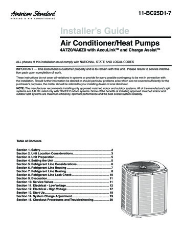
11-BC25D1-7Installer’s GuideAir Conditioner/Heat Pumps4A7Z0/4A6Z0 with AccuLinkTM and Charge AssistTMALL phases of this installation must comply with NATIONAL, STATE AND LOCAL CODESIMPORTANT — This Document is customer property and is to remain with this unit. Please return to service information pack upon completion of work.These instructions do not cover all variations in systems or provide for every possible contingency to be met in connection withthe installation. Should further information be desired or should particular problems arise which are not covered sufficiently for thepurchaser’s purposes, the matter should be referred to your installing dealer or local distributor.NOTE: The manufacturer recommends installing only approved matched indoor and outdoor systems. All of the manufacture’s splitsystems are A.H.R.I. rated only with TXV/EEV indoor systems. Some of the benefits of installing approved matched indoor andoutdoor split systems are maximum efficiency, optimum performance and the best overall system reliability.Table of ContentsSection 1. Safety. 2Section 2. Unit Location Considerations. 3Section 3. Unit Preparation. 5Section 4. Setting the Unit. 5Section 5. Refrigerant Line Considerations. 6Section 6. Refrigerant Line Routing. 7Section 7. Refrigerant Line Brazing. 8Section 8. Refrigerant Line Leak Check. 10Section 9. Evacuation. 11Section 10. Service Valves. 11Section 11. Electrical - Low Voltage. 12Section 12. Electrical - High Voltage. 17Section 13. Start Up. 18Section 14. System Charge Adjustment. 19Section 15. Checkout Procedures and Troubleshooting. 30
Section 1. Safety ! WARNINGThis information is intended for use by individualspossessing adequate backgrounds of electrical andmechanical experience. Any attempt to repair a centralair conditioning product may result in personal injuryand/or property damage. The manufacture or sellercannot be responsible for the interpretation of thisinformation, nor can it assume any liability in connection with its use. ! WARNINGThese units use R-410A refrigerant which operatesat 50 to 70% higher pressures than R-22. Use onlyR-410A approved service equipment. Refrigerantcylinders are painted a “Rose” color to indicate thetype of refrigerant and may contain a “dip” tube toallow for charging of liquid refrigerant into the system. All R-410A systems use a POE oil that readilyabsorbs moisture from the atmosphere. To limit this“hygroscopic” action, the system should remain sealedwhenever possible. If a system has been open to theatmosphere for more than 4 hours, the compressor oilmust be replaced. Never break a vacuum with air andalways change the driers when opening the systemfor component replacement. For specific handlingconcerns with R-410A and POE oil, reference RetrofitBulletin SS-APG006-EN and APP-APG012-EN. ! WARNINGLIVE ELECTRICAL COMPONENTS!During installation, testing, servicing, and troubleshooting of this product, it may be necessary to workwith live electrical components. Failure to follow allelectrical safety precautions when exposed to liveelectrical components could result in death or seriousinjury. ! CAUTIONIf using existing refrigerant lines make certain that alljoints are brazed, not soldered.! CAUTION Scroll compressor dome temperatures may be hot. Donot touch the top of compressor; it may cause minor tosevere burning.NOTE: It is recommended to install manufacturer approved matched indoor and outdoor systems.NOTE: All approved split systems are AHRI rated with onlyTXV/EEV indoor systems.NOTE: The benefits of installing approved indoor andoutdoor split systems are maxi mum efficiency, optimumperformance and the best overall system reliability. ! WARNINGUNIT CONTAINS R-410A REFRIGERANT!R-410A operating pressures exceed the limit of R-22.Proper service equipment is required. Failure to useproper service tools may result in equipment damageor personal injury.SERVICEUSE ONLY R-410A REFRIGERANT AND APPROVED POE COMPRESSOR OIL. ! WARNINGExtreme caution should be exercised when openingthe Liquid Line Service Valve. Turn counterclockwiseuntil the valve stem just touches the rolled edge. Notorque is required. Failure to follow this warning willresult in abrupt release of system charge and mayresult in personal injury and /or property damage.2 11-BC25D1-7
Section 2. Unit Location Considerations2.1 Unit Dimensions and WeightTable 2.1Unit Dimensions and WeightModelsH x D x W (in)Weight* (lb)4A7Z0024A45 x 34 x 373254A7Z0036B45 x 34 x 373254A7Z0048A/B45 x 34 x 374104A7Z0060A45 x 34 x 374104A6Z0024A45 x 34 x 373304A6Z0036B45 x 34 x 373354A6Z0048A/B45 x 34 x 374204A6Z0060A45 x 34 x 37420WH* Weight values are estimated (uncrated).DWhen mounting the outdoor unit on a roof, besure the roof will support the unit’s weight.Properly selected isolation is recommended toalleviate sound or vibration transmission to thebuilding structure.2.2 Refrigerant Piping Limits1. The maximum length of refrigerant linesfrom outdoor to indoor unit should NOTexceed sixty (60) feet.2. The maximum vertical change should notexceed twenty five (25) feet*.3. Service valve connection diameters areshown in Table 5.1.NOTE: For line lengths greater than sixty (60)feet, Refer to Refrigerant Piping ApplicationGuide, SS-APG006-EN or Refrigerant PipingSoftware Program, 32-3312-03 (or latest revision).StandardLine Set60’ MaxLine Length*35’ � MaxLineLength* Restricted to maximum vertical change of 25 ft.11-BC25D1-73
2.3 Suggested Locations for Best ReliabilityEnsure the top discharge area is unrestricted forat least five (5) feet above the unit.Avoid InstallNear BedroomsThree (3) feet clearance must be provided infront of the control box (access panels) and anyother side requiring service.Do not locate close to bedrooms as operationalsounds may be objectionable.Min 5’ UnrestrictedMin. 12” toShrubberyAvoid locations such as near windows wherecondensation and freezing defrost vapor canannoy a customer.Min 3’UnrestrictedAccess PanelPosition the outdoor unit a minimum of 12” fromany wall or surrounding shrubbery to ensureadequate airflow.Outdoor unit location must be far enough awayfrom any structure to prevent excess roof runoffwater or icicles from falling directly on the unit.Min. 12” toShrubberyMin. 12”to Wall2.4 Cold Climate Considerations (Heat Pump only)NOTE: It is recommended that these precautions be taken for units being installed in areaswhere snow accumulation and prolonged belowfreezing temperatures occur. Units should be elevated 3-12 inches abovethe pad or roof top, depending on localweather. This additional height will allowdrainage of snow and ice melted duringdefrost cycle prior to its refreezing. Ensurethat drain holes in unit base pan are not obstructed preventing draining of defrostwater.If possible, avoid locations that are likely toaccumulate snow drifts. If not possible, asnow drift barrier should be installed aroundthe unit to prevent a build-up of snow on thesides of the unit.Min. 12”SnowBarrierSnow Legs3-12” ElevationPad4 11-BC25D1-7
2.5 Coastal ConsiderationsIf installed within one mile of salt water, including seacoasts and inland waterways, models without factory supplied Seacoast Salt Shields require the addition of BAYSEAC001 (Seacoast Kit) at installation time.Section 3. Unit Preparation3.1 Prepare The Unit For InstallationSTEP 1 - Check for damage and report promptly to the carrier any damage found to the unit.STEP 2 - To remove the unit from the pallet,remove tabs by cutting with a sharp tool.Section 4. Setting the Unit4.1 Pad InstallationWhen installing the unit on a support pad, suchas a concrete slab, consider the following: The pad should be at least 1” larger than theunit on all sides. The pad must be separate from any structure. The pad must be level. The pad should be high enough above gradeto allow for drainage. The pad location must comply with National,State, and Local codes.11-BC25D1-75
Section 5. Refrigerant Line Considerations5.1 Refrigerant Line and Service Valve Connection SizesTable 5.1Line SizesService Valve Connection SizesModelVaporLineLiquidLineVapor LineConnectionLiquid A/B3/43/83/43/84A6Z0060A3/43/83/43/85.2 Factory ChargeAmerican Standard Heating & Air Conditioning outdoor condensing units are factory charged with the systemcharge required for the outdoor condensing unit, fifteen (15) feet of tested connecting line, and the smallestindoor evaporative coil match. See unit nameplate. If connecting line length exceeds fifteen (15) feet and/or a larger indoor evaporative coil is installed, then final refrigerant charge adjustment is necessary. UseCharge Assist or the Manual Charging procedure found in the outdoor unit Service Facts. Charge level canalways be verified with the Refrigerant Charging Chart found in the Service Facts.5.3 Required Refrigerant Line LengthDetermine required line length and lift. You willneed this later in STEP 2 of Section 14.Total Line Length Ft.Line LengthTotal Vertical Change (lift) Ft.5.4 Refrigerant Line InsulationImportant: The Vapor Line must always beinsulated. DO NOT allow the Liquid Line andVapor Line to come in direct (metal to metal)contact.Liquid LineVapor LineInsulation6 11-BC25D1-7
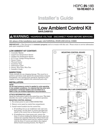
5.5 Reuse Existing Refrigerant Lines! CAUTION If using existing refrigerant lines make certainthat all joints are brazed, not soldered.For retrofit applications, where the existingindoor evaporator coil and/or refrigerant lineswill be used, the following precautions shouldbe taken: Ensure that the indoor evaporator coil andrefrigerant lines are the correct size. Ensure that the refrigerant lines are free ofleaks, acid, and oil.Important: For more information see publication number SS-APG006-EN.Section 6. Refrigerant Line Routing6.1 PrecautionsImportant: Take precautions to prevent noisewithin the building structure due to vibrationtransmission from the refrigerant lines.Comply with National, State, and Local Codes whenisolating line sets from joists, rafters, walls, or otherstructural elements.For Example: When the refrigerant lines have to be fastened to floor joists or other framing in a structure, use isolation typehangers. Isolation hangers should also be used when refrigerant lines are run in stud spaces or enclosed ceilings. Where the refrigerant lines run through a wall or sill, they should be insulated and isolated. Isolate the lines from all ductwork. Minimize the number of 90º turns.8 Feet MaximumJoist/RafterIsolatorSide View8 Feet MaximumLine SetSecure Vapor line from joists using isolators every 8 ft. SecureLiquid Line directly to Vapor line using tape, wire, or other appropriate method every 8 ft.Isolation From Joist/Rafter11-BC25D1-77
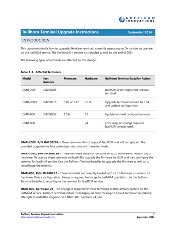
8 Feet MaximumWallIsolator8 Feet MaximumSide ViewLine SetSecure Vapor Line using isolators every 8 ft. Secure Liquid Linedirectly to Vapor Line using tape, wire, or other appropriatemethod every 8 ft.Isolation In Wall SpacesWallSealantDuctworkInsulationVapor LineIsolatorLine SetIsolation Through WallDO NOT hang line sets from ductworkSection 7. Refrigerant Line Brazing7.1 Braze The Refrigerant LinesSTEP 1 - Remove caps or plugs. Use a deburring tool to debur the pipe ends. Clean bothinternal and external surfaces of the tubingusing an emery cloth.8 11-BC25D1-7
STEP 2 - Remove the pressure tap cap andvalve cores from both service valves.STEP 3 - Purge the refrigerant lines and indoorcoil with dry nitrogen.STEP 4 - Wrap a wet rag around the valvebody to avoid heat damage and continue thedry nitrogen purge.Braze the refrigerant lines to the servicevalves.Continue the dry nitrogen purge. Do not remove the wet rag until all brazing is completed.Important: Remove the wet rag before stoppingthe dry nitrogen purge.NOTE: Precautions should be taken to avoidheat damage to basepan during brazing. It isrecommended to keep the flame directly off ofthe basepan.11-BC25D1-79
STEP 5 - Replace the pressure tap valve coresafter the service valves have cooled.Section 8. Refrigerant Line Leak Check8.1 Check For LeaksSTEP 1 - Pressurize the refrigerant lines andevaporator coil to 150 PSIG using dry nitrogen.150 PSIGSTEP 2 - Check for leaks by using a soapy solution or bubbles at each brazed location.Remove nitrogen pressure and repair any leaksbefore continuing.10 11-BC25D1-7
Section 9. Evacuation9.1 Evacuate the Refrigerant Lines and Indoor CoilImportant: Do not open the service valves untilthe refrigerant lines and indoor coil leak checkand evacuation are complete.0350MicronsSTEP 1 - Evacuate until the micron gauge readsno higher than 350 microns, then close off thevalve to the vacuum pump.ONOFFSTEP 2 - Observe the micron gauge. Evacuationis complete if the micron gauge does not riseabove 500 microns in one (1) minute.1 MIN.Once evacuation is complete blank off thevacuum pump and micron gauge, and close thevalves on the manifold gauge set.Section 10. Service Valves10.1 Open the Gas Service ValveImpo
American Standard Heating & Air Conditioning outdoor condensing units are factory charged with the system charge required for the outdoor condensing unit, fifteen (15) feet of tested connecting line, and the smallest indoor evaporative coil match. See unit nameplate. If connecting line