Transcription
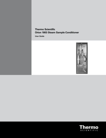
Thermo ScientificOrion 1803 Steam Sample ConditionerUser Guide
ROSS and the COIL trade dress are trademarks of Thermo Fisher Scientific Inc.AQUAfast, Cahn, ionplus, KNIpHE, No Cal, ORION, perpHect, PerpHecT, PerpHecTion, pHISA, pHuture, Pure Water, Sage, Sensing the Future, SensorLink,ROSS, ROSS Ultra, Sure-Flow, Titrator PLUS and TURBO2 are registered trademarks of Thermo Fisher.1-888-pHAX-ION, A , All in One, Aplus, AQUAsnap, AssuredAccuracy, AUTO-BAR, AUTO-CAL, AUTO DISPENSER, Auto-ID, AUTO-LOG, AUTO-READ,AUTO-STIR, Auto-Test, BOD AutoEZ, Cable-Free, CERTI-CAL, CISA, DataCOLLECT, DataPLUS, digital LogR, DirectCal, DuraProbe, Environmental ProductAuthority, Extra Easy/Extra Value, FAST QC, GAP, GLPcal, GLPcheck, GLPdoc, ISEasy, KAP, LabConnect, LogR, Low Maintenance Triode, Minimum StirRequirement, MSR, NISS, One-Touch, One-Touch Calibration, One-Touch Measurement, Optimum Results, Orion Star, Pentrode, pHuture MMS, pHuturePentrode, pHuture Quatrode, pHuture Triode, Quatrode, QuiKcheK, rf link, ROSS Resolution, SAOB, SMART AVERAGING, Smart CheK, SMART STABILITY,Stacked, Star Navigator 21, Stat Face, The Enhanced Lab, ThermaSense, Triode, TRIUMpH, Unbreakable pH, Universal Access are trademarks ofThermo Fisher. 2008 Thermo Fisher Scientific Inc. All rights reserved. All trademarks are the property of Thermo Fisher Scientific Inc. and its subsidiaries.The specifications, descriptions, drawings, ordering information and part numbers within this document are subject to change without notice.This publication supersedes all previous publications on this subject.
Table of ContentsGeneral Description . . . . . . . . . . . . . . . . . . . . . . . . . . . . . . . . . . . . 1Specifications . . . . . . . . . . . . . . . . . . . . . . . . . . . . . . . . . . . . . . . . . 2Principle of Operation . . . . . . . . . . . . . . . . . . . . . . . . . . . . . . . . . . 4Installation . . . . . . . . . . . . . . . . . . . . . . . . . . . . . . . . . . . . . . . . . . . . 5Operation . . . . . . . . . . . . . . . . . . . . . . . . . . . . . . . . . . . . . . . . . . . . . .6Shutdown . . . . . . . . . . . . . . . . . . . . . . . . . . . . . . . . . . . . . . . . . . . . . 7Troubleshooting . . . . . . . . . . . . . . . . . . . . . . . . . . . . . . . . . . . . . . . . 8Maintenance . . . . . . . . . . . . . . . . . . . . . . . . . . . . . . . . . . . . . . . . . . 8Assistance . . . . . . . . . . . . . . . . . . . . . . . . . . . . . . . . . . . . . . . . . . . . 9Warranty . . . . . . . . . . . . . . . . . . . . . . . . . . . . . . . . . . . . . . . . . . . . . . 9Ordering Information . . . . . . . . . . . . . . . . . . . . . . . . . . . . . . . . . . 10Thermo Scientific Orion 1803 Steam Sample Conditioner User Guide
IIThermo Scientific Orion 1803 Steam Sample Conditioner User Guide
General DescriptionThe Thermo Scientific Orion 1803 steam sample conditioning panel is apre-piped assembly that includes all the elements necessary to prepare steamand water samples for accurate and safe online analysis.There is a base configuration plus a variety of optional components. Thedrawing to the left shows a flow schematic and a general arrangementdrawing of the panel.The standard 1803 base model is 12” (width) x 36” (height) and is rated at3030 psig at 1000 F.Base Model Includes: Sample Shutoff Valve Sample Cooler (TF series) Variable Pressure Reduction Element, VREL Cooling Water Valves Temperature Indicator Back Pressure and Relief Valve Total Flow Indicator Thermal Shutoff Valve, TSVOptional Equipment: Pressure Gauge, Cat. No. 228714-A01 Cooling Water Site Gauge, Cat. No. 228710-A01 Position Switch Indicator for TSV, Cat. No. 228713-A01Thermo Scientific Orion 1803 Steam Sample Conditioner User Guide
SpecificationsThe base configuration includes a back panel with the sample isolationvalve, sample cooler, flow control valve, cooling water inlet and outletvalves, back pressure valve, temperature and flow indicators and a thermalshutoff valve.Sample Isolation Valve (V-1)The sample inlet isolation valve is used to isolate flow to the sample panelonly. It is not to be used for throttling, due to the damage that will occuron the seat. The valve is selected to meet the pressure and temperatureoperating conditions of the panel.Primary Sample Cooler (SC-1)The standard cooler used is a Model TLF-4225, which has a removableshell. Other models are available upon request. If chlorinated coolingwater or high chloride/bromide cooling water is used, the ModelTLF-42B5 should be used.Flow Control Valve (VREL)The VREL is a non-wearing rod-in-tube pressure reducing/flow controldevice. A unique advantage of this type device is the ease at which dirt canbe passed through the system.Cooling Water Throttling Valve (V-2)The cooling water is throttled on the downstream side of the cooler, not theinlet side. This valve allows adjustment of the sample temperature withoutwasting cooling water.Cooling Water Inlet Isolation/Vent Valve (V-3)The 3-way isolation/vent valve protects the cooler shell side by eliminatingthe possibility of isolating the cooler while the sample may still be flowing.Either cooling water will be available to the cooler shell or the cooler shellwill be vented to the atmosphere.Back Pressure/Relief Valve (BPR/RV)The fixed back pressure/relief valve will hold a constant 20 psi pressure tothe monitor(s) at all times. The discharge from the valve is used to takegrab samples. Thermo Scientific Orion 1803 Steam Sample Conditioner User Guide
Temperature Indicator (TI)The temperature indicator is used to read the temperature of the samplebefore it goes on to the monitor(s).Flow Indicator (FI)The flow indicator is used to read the total flow through the system. Thesample throttling, VREL, must be used to set the flow rate.Thermal Shutoff Valve (TSV-1)The thermal shutoff valve is a self contained, mechanical device thatprotects both the instrumentation as well as plant personnel from highsample temperatures. The TSV is a spring loaded, latching design with allwetted metals of 316 stainless steel.Optional ComponentsPressure Gauge (PI)Gives sample pressure readout at the monitor connection. Under normaloperation this gauge will read approximately 20 psig.Cooling Water Sight Glass (FG)Allows panel operator to view cooling water flow at outlet of sample cooler.High Temperature Indicating SwitchA position indicating switch can be provided on the TSV, to enable remoteindication of high sample temperature.Thermo Scientific Orion 1803 Steam Sample Conditioner User Guide
Principle of OperationCooling Water Circuit – ShellsideThe cooling water must be throttled on the outlet side of the cooler, notthe inlet side. This approach gives the maximum cooling water pressureinside the cooler shell, which in turn assures the highest possible boilingpoint. Boiling should be eliminated since it not only encourages scaling,but also causes tube vibration and eventual fatigue failure.Note: The sample isolation valve is only for shutting off the sampleline. It must never be used to throttle sample flow. When the pressure isreduced across a partly closed valve and the sample is at or near saturationtemperature, the sample will flash into a steam/water mixture. This candamage the valve seat so that it may no longer completely shut off sampleflow when repairs or replacements are needed downstream. It can alsocause water hammer in the sample cooler when the steam bubbles collapse.Sample CircuitThe sample first flows through an isolation valve.The sample then flows through the primary cooler, where most of the heatis removed, then into a VREL for pressure reduction and flow control. TheVREL is a pressure reducing/flow control device.The sample then flows through a flow meter and then into a constantpressure zone. The constant pressure is maintained by a fixed backpressure/relief valve. The pressure will remain constant, independent ofsource pressure variations.It is important to have constant sample flow past the sensor. Because thepressure is constant at this point, the flow through the monitor will remainconstant (if adequate total flow is available). The fixed back pressure/reliefvalve also acts as a sample line relief valve. There is a capped fitting at theoutlet of the flow meter for connecting to customer supplied monitors.The grab sample flow is the discharge from the fixed back pressure/reliefvalve. Thermo Scientific Orion 1803 Steam Sample Conditioner User Guide
InstallationReceiving and Mounting1. Examine the unit for any shipping damage. If in doubt, take picturesof the suspect area. Examine the unit for any visible damage. Reportdamages to the shipper immediately. This is the responsibility ofthe consignee.2. Bolt the unit to the wall using four 3/8” bolts. Mounting theunistrut to the wall then mounting the SL to the unistrut will simplifythe installation.ConnectionsStep 1: Connect the cooling water inlet and outlet connections onthe coolers.Inlet (bottom), connection #4 is 1/2” FNPTOutlet (top), connection #3 is 1/2” FNPTStep 2: Connect the sample inlet/outlet and optional sink drain lines.Sample lines are 1/4” compressionOptional sink drain line is 1” FPTThermo Scientific Orion 1803 Steam Sample Conditioner User Guide
Operation1. Open the sample cooler cooling water outlet valve (V-2) to the fullopen position.2. Open the sample cooler cooling water inlet valve (V-3) to the openposition (handle in the 9 o’clock position).3. Close the VREL by turning clockwise. Do not overtighten it. TheVREL is not a shutoff valve.Note: When starting up a sample line always be sure that the rods arefully inserted (turn handle clockwise to insert rods) before openingthe sample isolation valve. When the rods are fully inserted, the yokebottoms in the barrel. When the rods are fully retracted, the yoke isstopped by the seal. Do not try to turn the handle at these locationsby using extra force. The threads will be damaged. After opening theisolation valve, adjust the setting of the VREL until the desired flowrate is established.4. If the thermal shutoff valve (TSV-1) is present, make sure that the valveis reset by looking at the button. If the red indicator ring is not visible,it is ready for operation. If it is visible, push the button until the valvelatches and the red indicator ring is not visible.5. Open the sample inlet isolation valve (V-1) to the full open position.6. Adjust the VREL, by turning counterclockwise, until the desiredsample flow rate is achieved. The sample will be discharging throughthe BPR/RV. The sample must be discharging from the BPR/RV toensure that the sample flowing to the monitor will be at a constantpressure and therefore constant flow rate. The flow should be enoughto establish turbulent flow in the sample lines between the samplesource and the rack. The flow must also be in excess of that requiredby the monitors so that there is enough for a grab sample. Typically1200 cc/min is recommended for 1/4” sample lines.7. Monitor the temperature indicator (TI) to ensure that the sampletemperature is not exceeding either a limit determined by theinstrument requirements or personnel limitations. If the samplebecomes too hot, check for cooling water flow and temperatures andreduce the sample flow rate.8. Adjust the flow meter in each monitor line to set the proper flow foreach. Check to be sure that the sample is still flowing from the backpressure valve. If not, open the VREL until a solid sample stream isestablished. This is the grab sample source. If it takes too long to takea grab sample, temporarily open the flow control valve further. Whenfinished taking the grab sample, be careful not to cut back flow lowerthan the turbulent flow rate or the rate to maintain a solid stream. Thermo Scientific Orion 1803 Steam Sample Conditioner User Guide
9. If the thermal shutoff valve trip (the red indicating band is visible),the sample flow to the BPR/RV and instruments will be stopped.This tripped position indicates that the sample temperature exceededthe preset 104 F trip point. After verifying that the cooling water isavailable and flowing, close the VREL and then push the button in.It may be necessary to hold the button in momentarily until all hightemperature sample is flushed from the system. Re-establish flow asbefore, see step 6.Note: The VREL is a rod-in-tube device. The pressure of the incomingsample is reduced as the liquid is forced to travel through the narrow gapbetween the tapered rod and the tube inside diameter. Because the workis done over the entire length of the rod, localized stresses are held to aminimum. The result is a very long service life compared with devices inwhich the pressure drop is taken over a very short distance (fixed orifice,pressure regulator, etc.). In those devices material erosion frequently causesloss of function.Note: The VREL is not a shutoff valve. Minimum flow obtainable isabout 400 cc/min or less.Note: The flow through the VREL can be adjusted, while the sample isflowing, by changing the position of the rods in the tube. Turning thehandle moves the rods in or out on a lead screw. If dirt in the sampleblocks sample flow, the rods can be fully retracted to allow sample pressureto blow the dirt through. The sample line need never be shut off, northe VREL disassembled to accomplish this. This is very important to theoperator as he or she tries to get critical samples while boiler pressure isrising or falling during start-up or shutdown.Shutdown1. Close the sample inlet isolation valve (V-1).2. Close the VREL (cloc
Thermo Scientific Orion 1803 Steam Sample Conditioner User Guide 1 The Thermo Scientific Orion 1803 steam sample conditioning panel is a pre-piped assembly that includes all the elements necessary to prepare steam and water samples for accurate and safe online analysis. There is a base configuration plus a variety of optional components. The