Transcription
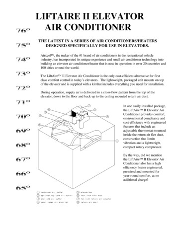
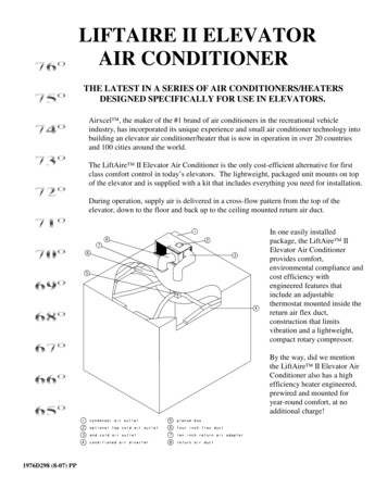
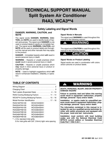
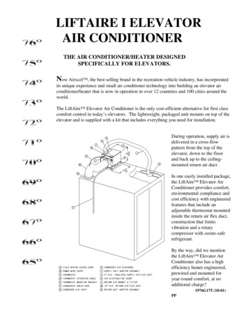
LIFTAIRE I ELEVATORAIR CONDITIONERTHE AIR CONDITIONER/HEATER DESIGNEDSPECIFICALLY FOR ELEVATORS.Now Airxcel , the best selling brand in the recreation vehicle industry, has incorporatedits unique experience and small air conditioner technology into building an elevator airconditioner/heater that is now in operation in over 12 countries and 100 cities around theworld.The LiftAire Elevator Air Conditioner is the only cost-efficient alternative for first classcomfort control in today’s elevators. The lightweight, packaged unit mounts on top of theelevator and is supplied with a kit that includes everything you need for installation.During operation, supply air isdelivered in a cross-flowpattern from the top of theelevator, down to the floorand back up to the ceilingmounted return air duct.In one easily installed package,the LiftAire Elevator AirConditioner provides comfort,environmental compliance andcost efficiency with engineeredfeatures that include anadjustable thermostat mountedinside the return air flex duct,construction that limitsvibration and a rotarycompressor with ozone-saferefrigerant.By the way, did we mentionthe LiftAire Elevator AirConditioner also has a highefficiency heater engineered,prewired and mounted foryear-round comfort, at noadditional charge?1976G175 (10-01)PP
SERVICE INFORMATIONWe believe that you will be pleased with the performance of the RVP LiftAire Elevator Air Conditioner. Thisunique product was specifically designed for installation on elevators. Should you need assistance in theinstallation of the product, or should you need service assistance after the unit is installed, please contact ourexclusive sales and service agent for this product line listed below:For Installations In North America:Elevator Motors Corporation80 Carolyn Blvd.Farmingdale, NY 11735-1525631-293-4220 (Voice)631-293-2714 (Fax)info@elevatormotors.com (E-Mail)Attention: Mark or Robert LaneFor Installations Outside North America:Global Elevator Products, Inc.P.O. Box 147Plainview, NY 11803-0147516-932-7968 (Voice)516-932-0987 (Fax)info@globalelevator.com (E-Mail)2
1. WARNINGSIMPORTANT NOTICEWARNING - SHOCK HAZARDThese instructions are for qualified individuals speciallytrained and experienced in installation of this type ofelectrical equipment and related system components.To prevent the possibility of severe personal injury orequipment damage due to electrical shock, always be surethe electrical power source to the appliance isdisconnected during installation and service.Installation and service personnel are required by somestates to be licensed. PERSONS NOT QUALIFIEDSHALL NOT INSTALL NOR SERVICE THISEQUIPMENT.CAREFULLY FOLLOW ALL INSTRUCTIONS ANDWARNINGS IN THIS BOOKLET TO AVOID DAMAGETO THE EQUIPMENT, PERSONAL INJURY OR FIRE.NOTEWARNINGThe words “Shall” or “Must” indicate a requirementwhich is essential to satisfactory and safe productperformance and installation.Improper installation may damage equipment, can createa hazard and voids the warranty.The use of components not tested in combination with thisunit will void the warranty, may make the equipment inviolation of state codes, may create a hazard and may ruinthe equipment.The words “Should” or “May” indicate a recommendationor advice which is not essential and not required but isuseful or helpful.2. COMPONENT MATCH-UP1.6531D692 (115 V, 60 Hz) or 6571B662(240 V, 50 Hz) Package Air Conditioner2.36531A625 Installation Kit (Included)
3. SPECIFICATIONS AND UNIT IDENTIFICATION Air Conditioner Only - Does Not Include Condensation Evaporator#Evaporator Dimensions:WeightWidthDepthHeight412 lbs.11.85"13.63"8.125"
4. UNIT DEPICTION FIGURES5. GENERAL INFORMATIONThe 6531 (115 volt) and 6571 (240 volt) series package airconditioners are intended for installation on the roof ofelevator cabs or like-sized indoor use contrivances.Installation area should be sufficient to allow proper cutoutsand mounting without cutting vital frame members orelectrical wiring. Structural members should not createrestrictions to airway ducts required by air conditioner.Conditioned air is delivered from the air conditioner to theinterior of the enclosure through ducting that is supplied inInstallation Kit #6531A625.The system return air duct, return air filter, return air bonnetand thermostat are also found in the Installation Kit.The air conditioner is powered by a 115 volt, 60 Hz, 1 Phase,20 Amp electrical service for the 6531 series and 240 volt, 50Hz, 1 Phase, 10 Amp electrical service for the 6571 series.A recommended installation is shown in Figure 1. Actualmounting and placement can vary according to existingconditions.5
6. UNIT INSTALLATIONThe air conditioner draws in topside air to cool thecondensing coil.9)Cut a 10 1/8" square opening in the cab top as far aspossible from the intended location of the supply airduct into the cab. Position 10" diameter return aircollar assembly with the thermostat/bracket over theopening. Fasten the collar to the cab top with rivetsor screws. Using quality duct tape, seal the seamsaround the perimeter of the collar assembly.10)Install the supply air distribution scoop inside theconditioned space in an area as far from the returnair as possible. Air from the scoop should have aclear path into the conditioned area. Attach thescoop with adhesive, straps, brackets or by fasteningthrough the part. If attaching with fasteners, predrill any clearance holes in the scoop to preventcracking during installation. It is good practice tomount the scoop away from possible heat producingdevices, such as lights, fixtures, etc.11)Provide a 6" dia. hole in the roof to allow passage ofthe insulated 4" flex duct. The duct connectsbetween the 4" collar at the unit and the ovalopening at the air scoop. Secure the duct with 2 ofthe 4 cable ties provided in the Installation Kit.12)Attach the 7/8" I.D. condensate drain hose to theunit drain pan. Secure with hose clamp.13)Determine the most direct and shortest length of ductto be used to connect the 10" diameter uninsulatedreturn air flex duct to the 10" diameter collarassembly installed in Step 8. Cut a small slitthrough the 10" diameter uninsulated return air flexduct directly above the 10" diameter collar assemblyand route the thermostat extension cable through theslit in the duct. Cut off any excess duct and attachthe duct to the return air bonnet using the duct tiesprovided. Seal the duct where the thermostat cableexits with a quality duct tape.14)Connect the 10" flex duct between the return airbonnet and the adapter installed at Step #8. Securewith 2 cable ties.15)Plug the remaining end of the cable into the airconditioners 4 pin thermostat connector.The condensing airflow is drawn in from the end of the airconditioner (across the condensing coil) and discharged outthrough the top of the appliance (through the dischargeopening).To provide adequate condensing airflow, the installer mustadhere to the following guidelines:1)The topside air path to the condensing coil should beas direct and non-restrictive as possible.2)Any decorative grille or louver used as an openingfor condenser airflow should have a minimum of 90square inches of free area.3)Do not block or restrict the discharge or return airopenings.4)Ensure that there are no structural members orpanels which would serve to cause condenserdischarge air to recirculate into the condenser returnair.5)Attach the crimped adapter to the air conditioningunit using the four (4) long screws found in thesmall parts package.6)The supply duct adapter is installed to exitconditioned air upward. Attach the adapter to theunit using the four (4) short screws supplied in thesmall parts package.7)Mount the air conditioning unit by securing it to themounting surface with bands or brackets. If usingcondensate evaporator with the air conditioner,elevate the air conditioner 4-5 inches to insureproper drainage of the condensate from the airconditioner drain pan to the evaporator.8)Mount the thermostat to the thermostat mountingbracket using the screws provided with thethermostat. Connect extension cable to thethermostat cable. Attach thermostat with mountingbracket to the 10" diameter return air collar assemblyusing two (2) sheet metal screws.DANGER - SHOCK HAZARDDo not drill any openings into this air conditioner. Whenattaching ducting directly to the air conditioner, use onlythe pilot holes already provided. Drilling new openingsand inserting screws may damage either the refrigerationcircuit or electrical wiring, causing possible equipmentdamage, personal injury or death.6
7. 115 (240) VAC - ELECTRICAL WIRING1.WARNING - SHOCK HAZARDA)High voltage wiring must be routed througha separate opening in the outer cabinet.This opening is referred to as the “powerwireentry” (See Figure 1 (B), page 3). RVProducts provides a 7/8" diameter openingfor ½" conduit. A knockout for 3/4"conduit is also provided.B)Do not allow excess wiring to contactelectrical terminals, sharp screw ends oredging that can cut or damage the wiringinsulation.C)After connecting the ground wire to thegrounding lug, verify that the ground wire(which in some instances will be barecopper) cannot come into contact with anyhigh voltage terminal.To prevent the possibility of severe personalinjury or equipment damage due to electricalshock, always ensure all the electrical power isdisconnected and removed before beginninginstallation.2.3.This air conditioner contains a compressorrefrigeration system and requires power from a 115(240) volt electrical circuit. The circuit connects to aterminal block inside the main unit.High Voltage Routing SpecificationsWhen routing the high voltage supply wiring, thefollowing guidelines must be followed:8. ADDITIONAL INSTALLATION INSTRUCTIONSthe type of operation you require. When thethermostat is installed in the cab, it must be able tosense cab temperature to operate properly. If placedwithin the fixture area of the cab, there must be aperforated cover to allow cab air access to thethermostat. Locating the thermostat anywhere elseaffects the proper operation of the LiftAire I unitand cooling of the elevator cab as designed.The LiftAire I Series of air conditioners are specificallydesigned and constructed for use on new elevatorinstallations, modernizations and retrofits of existing elevatorcabs. They are provided with all the materials needed toproperly cool and/or heat an elevator cab. To ensuremaximum efficiency and operation, the following should beadhered to:1.Supply and return registers in the cab should notrestrict airflow into and out of the cab. Anyresistance of the airflow will limit the effectivenessof the unit and create wind noise. The minimumamount of open area in the supply register shouldbe 13 square inches and the return register, 79square inches. The return air and supply airregisters should be as far away from each other toensure proper air recirculation in the cab and back tothe air conditioner.2.While the installation kit provides 12.5 feet of supplyand return air flexible duct, in order to limit airflowresistance, all duct connections should be the mostdirect and the shortest possible. Cut any extraflexible duct not required, connect flexible duct perprevious installation instructions (page 4) anddiscard any extra material.3.Ensure that the thermostat is installed in thereturn duct or the cab. If using the standardthermostat, check that the temperature and operationsettings are correct. If using the automaticthermostat, make sure the unit is programmed for4.7If you are retrofitting an existing cab for normaloperating conditions, it may not be necessary to usethe fan supplied in the original cab. The LiftAireI air conditioner has a fan that will run continuouslywith proper settings of the thermostat. If you allowthe cab fan to operate during normal conditions youwill bring hot, cold or humid hoistway air into thecab, thereby defeating the purpose of the airconditioner and its effectiveness. If it is permitted,remove the original fan to prevent allowing warmhoistway air into the cab during ascent anddescent of elevator. If available, you can use theoriginal fan’s opening for the return air registerprovided it has 79 square inches of open area and isfar enough away from the supply air register toensure proper recirculation of the cool air. If usingthe LiftAire I on a new installation, a cab fan isprobably not required.
5.All supply and return registers with duct work intothe cab must be manufactured and installed toprevent any air leaks and losses of the cold supply airfrom the air conditioner and return air back to the airconditioner.6.Never install the condensate evaporator under thereturn or supply air ducts. This can cause wateraccumulation, damage to the ducts and damage tothe cab.7.It is the responsibility of the installer to ensure thatthe installation meets any and all building, electricaland other applicable codes.9. MAINTENANCE INSTRUCTIONSThe LiftAire I Series of air conditioners require very littlemaintenance during normal operating conditions. Thefollowing are general requirements that should be performedevery 4-6 months.1.Air filters should be inspected and washed on aregular basis. The filters are reusable after beingwashed.2.Evaporator and condenser coils should be inspectedand, if dirty, cleaned on a regular basis. Remove byhand any paper or debris that might have collectedon the coils and blow compressed air through thecoils. This should not have to be done very oftenunless the shaftway and installation are in a verydirty environment.3.Inspect and clean the condensate drain pan. Ensurethe drain hole and hose are clear of debris to allowany condensate to properly drain.4.If a condensate evaporator is used, inspect to ensurethere is no debris on the guard or in the evaporatorpan. Ensure drain hole and hose are clear of debris.5.CONNECTION (ABOUT 3/4" BARE WIRE).INSERT THE SUPPLY WIRES INTO THEELECTRICAL CONNECTOR CLAMP.SHEATH MUST PROTRUDE PAST CLAMPBUSHING INSIDE THE BOX. MAKE SURESHEATH CABLE IS CENTERED IN CLAMPBEFORE TIGHTENING IT. DO NOTOVERTIGHTEN!! THIS COULD RESULTIN PINCHING THROUGH THE PLASTICWIRE INSULATION AND CAUSESHORTING OR “HOT” WIRES TOGROUND (SHOCK HAZARD). THE CLAMPIS INTENDED FOR STRAIN RELIEF OF THEWIRES. SLIGHT PRESSURE IS USUALLYSUFFICIENT TO ACCOMPLISH THIS.IF OTHER THAN NON-METALLIC CABLESARE USED FOR SUPPLY CONDUCTORS,APPROPRIATE STRAIN RELIEFCONNECTORS OR CLAMPS SHOULDBE USED.IN NO CASE SHOULD CLAMPING ORPINCHING ACTION BE APPLIED TO THEINDIVIDUAL SUPPLY LEADS (NEUTRALAND “HOT” WIRES).If an automatic thermostat is used, check the LCDdisplay and observe if the word “BATTERY” isflashing. If it is displayed, the “AA” alkalinebatteries are low and should be replaced. Seethermostat operating manual for battery replacementinstructions.DANGER - SHOCK HAZARDTO PREVENT THE POSSIBILITY OF SHOCKINJURY FROM APPLIANCE OPERATION:THE WHITE WIRE MUST BE CONNECTEDTO NEUTRAL IN THE SERVICE BOXENTRANCE AND THE MECHANICALGROUND MUST BE CONNECTED TO AGROUNDING LUG EITHER IN THESERVICE BOX OR THE MOTORGENERATOR COMPARTMENT.DANGERWHEN USING NON-METALLIC SHEATHSUPPLY CABLES (ROMEX, ETC.); IFALLOWED BY BUILDING, ELECTRICALOR APPLICABLE CODES, STRIP SHEATHBACK TO EXPOSE 4-6 INCHES OF THESUPPLY LEADS. STRIP THE INDIVIDUALWIRE LEAD ENDS FOR WIREIn order to utilize smaller gauge, less expensive followercables; it may be economical to provide a stepdowntransformer at the elevator car to provide power for the airconditioner.8
10. THERMOSTAT AND 24 VAC WIRINGThe thermostat should be mounted on the return air ductmounting bracket (See Figure 1 (C), page 5). The airconditioner and thermostat connect using the plug-inextension cable provided in the 6531A625 Installation Kit.THERMOSTAT OPERATING AND WIRINGREQUIREMENTSThe 6531 (115 volt) and 6571 (240 volt) series airconditioners are designed to be controlled by the 24 VACthermostat provided in the installation kit or by our optionalautomatic thermostat.The chart below details system functions.9
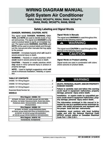
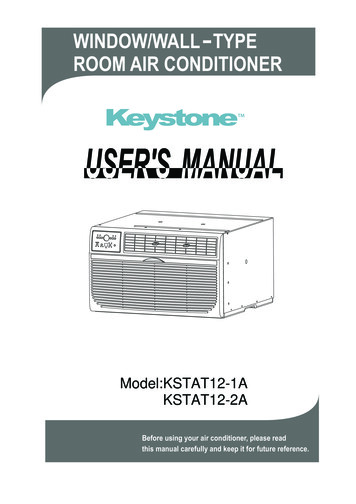
11. PRE-CHECK PRIOR TO POWER UP1.Before engaging power to any system, ensure thefollowing:A)All tools have been removed from theequipment;B)All wiring is attached, routed and properlysecured according to applicable codes;C)All panels (both mechanical and electrical)are properly in place;D)The thermostat system is switched to the“OFF” position; andE)All co-workers have been warned that theequipment is about to be energized.2.System wiring may be checked by referring to thewiring diagram located on either the back of thewiring box door or in this manual (See page 11).3.After complying with Steps 1 and 2, engage power toall systems and begin checkout procedure.12. INSTALLATION INSTRUCTIONS FOR6531-3251 (115 VAC-20 AMPS) AND 6571-3251 (240 VAC-10 AMPS)CONDENSATE EVAPORATORPACKAGE CONTENTS1 - Condensate Evaporator Assembly1 - Unit Drain Filter Pad2 - Filter Pad Hold-Down Clips1 - 3/8" I.D. x 4 Ft. Overflow Hose1 - Hose Clamp4 - Evaporator Mount Clips1 - Evaporator GuardC.Route a length of 7/8" I.D. drain hose provided withthe air conditioner through a grid section to providedrainage into the evaporator without touching theevaporator. The drain hose will fit snugly through agrid section. Do not allow the drain hose to routeabove the a/c unit drain pan at any point.D.Attach the 3/8" I.D. hose to the evaporator using theclamp provided. This hose will pass through anevaporator guard grid section. Free end of this hosewill be inserted and secured into the remaining 7/8"I.D. hose which passes to the bottom of the elevator.The 7/8" I.D. hose should be clamped to the elevatorside. Ensure that a minimum of 4 inches ofevaporator overflow hose is inserted and secured intothe larger drain hose. Do not allow the overflowhose to route above the evaporator pan at anypoint.E.Connect power supply per all building, electrical andother applicable codes.FILTER INSTALLATIONCenter filter pad over condensate drain fitting inside of unitdrain pan and secure filter pad with hold-down clips whichslide over the edge of the unit drain pan to hold the filter inplace (See Figure 2).EVAPORATOR INSTALLATIONA.B.The elevator air conditioner should first be installedfollowing the instructions provided with the unit.The air conditioner must be installed at least 5"higher than the mounting surface for the condensateevaporator to allow for proper drainage (SeeFigure 3).Install the condensate evaporator with four screwsthrough the mounting flanges so the evaporator islevel and will not shift. Position the evaporatorguard basket over the evaporator, routing the conduitthrough a grid section. Secure evaporator guard tothe base using the four clips provided. Position theguard to allow the overflow hose direct entry througha grid section to the evaporator.FIGURE 210
FIGURE 311
LIFTAIRE ELEVATOR AIR CONDITIONERFEATURES Lightweight, 75 lb. unit mounts easily in virtually any position on top of the elevator. Self-contained, packaged design for easy installation.Compact rotary compressor saves space and weight.Rated at 7,100 BTUH nominal cooling capacity.Mechanical heat/cool thermostat mounted in return air flex duct for secure settings and more accurate temperature sensing. 15' umbilicalfor remote thermostat mounting. Optional automatic changeover heat/cool thermostat available.Standard 1600 watt electric heater delivers 5,600 BTUH heat capacity.Fan can be set to operate continuously for improved air circulation and filtration.150 cubic feet per minute airflow rate.Compressor hermetically sealed at factory for leakproof refrigerant flow and efficient operation.Black finish on supply air diverter conceals it in the gap between the false ceiling and interior wall.Compressor and outer cabinet are mounted on shock absorbing rubber for added durability and noise reduction.Long lasting copper tubing is fabricated with shock loops to strengthen the system’s vibration resistance.Gas-flux brazed joints on the tub
The LiftAire Elevator Air Conditioner is the only cost-efficient alternative for first class comfort control in today’s elevators. The lightweight, packaged unit mounts on top of the elevator and is supplied with a kit that includes everything you need for installation.