Transcription
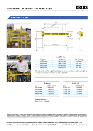
Sealing ElementsTechnical Handbook O-rings12. O-ring Gland DesignVisit: www.o-ring.infoWoque rldwidefeatuonli res nne!owuniSave time calculating and designing O-ring grooves and verify the O-ringsealing performance by checking parameters like o-ring compression, freegroove volume, o-ring inner diameter stretch and even much more.The ERIKS O-ring design calculator features the calculation of: o-ring dimensions for the use in a specific groove groove dimensions for the use of a specific o-ring evaluation of both, any combination of o-ring and groovefor axial seals with inner or outer pressure, piston seals and rod seals.Worldwide unique online calculation tool taking into consideration of thethermal expansion of the groove and the O-ring. As well as the chemicalvolume swell or shrinkage of the O-ring.Choose between more than 30 groove materials and 11 O-ring compounds!Benefit from a modern user friendly design and be guided from design recommendations from info boxes. Easy to use PDF output Saving of your designs Easy search for ERIKS standard O-rings131All the information in this documentation has been compiled with the greatest of care.Despite this we can bear no responsibility whatsoever for any errors present in the documentation. The recommendations are intended as guidelines.www.eriks.info
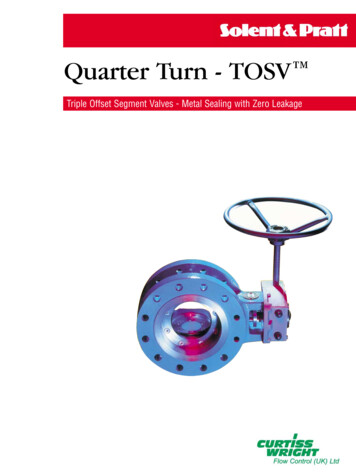
Sealing ElementsTechnical Handbook O-rings12. O-ring Gland DesignThe following pages contain basic O-ring gland design information. Please contact the local ERIKS representative if an application does not clearly fall into these design parameters.Dovetail sealAlso here there is a metal to metal contact as long as the construction will not deform under system pressure. (fig. 1-30).Static ApplicationsThere are five types of static O-ring applications: Flange seal Radial seal Dovetail seal Boss seal Crush sealBoss sealThe groove dimensions are incorporated in the standard dimensions.Surface Finish Static GroovesStraight-sided grooves are best to prevent extrusion or nibbling.Five degree sloping sides are easier to machine and are suitablefor lower pressures. Surface finishes up to 64 to 125 RMS withno burrs, nicks, or scratches are recommended.Flange Seal (Axial Seal)In flange seal glands, the two flanges are assembled with metalto metal contact. So in fact there is no remarkable gap and norisk for extrusion of the O-ring as long as the construction doesnot deform under system pressure. (fig. 1-26).When system pressure is from the outside, the groove insidediameter is of primary importance and the groove width thendetermines the outside diameter. When system pressure is fromthe inside the reverse is true.Radial SealBecause the metal parts are pressed or screwed together there isalways a clearance gap with risk for extrusion. (fig. 1-27).PressureoutsideThe method used to produce the finish is important. If the finish is produced by machining the part on a lathe, or by someother method that produces scratches and ridges that follow thedirection of the machinehead, a very rough surface will still sealeffectively.Other methods, however, such as end milling, will producescratches that cut across the O-ring. Even these may have arather high roughness value if the profile across them showsrounded scratches that the rubber can readily flow into.PressureinsideFig. 1-26Fig. 1-27x surface finish in µ Ra132Fig. 1-30All the information in this documentation has been compiled with the greatest of care.Despite this we can bear no responsibility whatsoever for any errors present in the documentation. The recommendations are intended as guidelines.www.eriks.info
Sealing ElementsTechnical Handbook O-rings12. O-ring Gland DesignDynamic ApplicationsThere are three types of dynamic applications: Reciprocating Seal Oscillating Seal Rotating SealApplication in reciprocating and oscillating motionsGroove dimensions for reciprocating and oscillating applicationsare the same.Dynamic applications, due to the motion against the O-ring, aremore complicated than static applications. Fluid compatibilitymust be more carefully scrutinized because a volume swell ofmore than 20% may lead to difficulties with high friction problems and only a minimum of shrinkage, at most 4%, can be tolerated to avoid leakage problems.Because of the movement between the gland parts there always isa clearance gap with a potential risk for extrusion of the O-ring.O-ring seals are best in dynamic applications when used onshort stroke, relatively small diameter applications. Long stroke,large diameter seals are more susceptible to spiral failure.Application of O-rings in rotary motionsIn a rotating application a shaft continuously rotates in the insidediameter of the O-ring, causing friction and heat. Because rubber is a poor conductor of heat, the O-ring can loose its properties. To minimize or reduce wear, the following could be done;however consult the local ERIKS representative: confirm amount of squeeze. use the smallest possible cross section. select an O-ring with internal lubri cation or use low frictionminerals. do not exceed a temperature of 212 F (100 C). do not use a shaft which is larger than the inside diameter ofthe O-ring. provide lubrication. do not let the O-ring rotate in the groove, only relative to theshaft. rough sealing surfaces of the groove will prevent rotation. check surface finish (may be too rough)Installing the O-ringMating metal surfaces are generally of different metals, with onemetal being softer than the other. The O-ring groove should beput in the softer of the metals. In the event that the metals wearon each other the harder metal will be less damaged, thus insuring a good sealing surface.Surface Finish for Dynamic GroovesStraight-sided grooves are best to prevent extrusion or nibbling.Five degree sloping sides are easier to machine and are suitablefor pressures up to 1500 psi. (100 bar). The rubbing surfacesshould be 8 to 16 RMS without longitudinal or circumferentialscratches. Best surfaces are honed, burnished, or hard chromeplated. Finishes of dynamic contacting surfaces have a lot to dowith the life of the O-ring seals. Appropriate surface finishes areimportant. Limits of maximum roughness for glands are given.Rougher finishes will cause excessive wear. Finer finishes reducelubrication to the O-ring and may result in stick slipping andirregular wear. Surface roughness values less than 5 micro inches (0,15µmRa) are not recommended for dynamic O-ring seals.The surface must be rough enough to hold small amounts of oil.Finishes below 5 RMS wipe too clean for good moving seal life.Steel or cast iron cylinder bores are preferred. They should bethick enough not to expand or breathe with pressure, otherwisethe radial clearance gap may expand and contract with pressurefluctuations-causing nibbling of the O-ring.133All the information in this documentation has been compiled with the greatest of care.Despite this we can bear no responsibility whatsoever for any errors present in the documentation. The recommendations are intended as guidelines.www.eriks.info
Sealing ElementsTechnical Handbook O-rings12. O-ring Gland DesignFrictionIn normal applications harder materials provide less friction thansofter materials. However, the higher the hardness of the O-ring,above 70 Shore A, the greater the friction. This is because thecompressive force at the same squeeze, is greater than withsofter materials.Compound swell decreases the hardness and may increase friction. The lower the operating temperature the harder the sealbecomes which can also increase friction. However, thermal contraction of the seal material which reduces effective squeeze mayoffset any increased friction caused by an increase of hardness.Seal extrusionIf the radial clearance gap between the sealing surface and thegroove corners (clearance gap) is too large and the pressureexceeds the deformation limit of the O-ring, extrusion of theO-ring material will occur.When this happens, the extruded material wears or frays withcycling and the seal starts to leak.Breakout friction is the force necessary to start relative motion.This is dependent upon the length of the time between cycles. Italso depends on the surface finish of the metal, the rubber hardness, squeeze, and other friction-affecting factors. After standing10 days, the breakout friction will be 2 to 5 times the friction ofa seal under light load. Breakout friction can be reduced by utlizing softer O-ring or specially modified compounds.Running friction depends on two factors: the force exerted on thering's rubbing surface by the compression force of the squeezeand the force of the system's pressure against and tending todistort the O-ring into a "D" shape. The former depends on thehardness of the O-ring, its percentage-squeeze and the length ofthe rubbing surface.The surface over which the O-ring will slide also becomes veryimportant. It must be hard and wear resistant, it must be sufficiently smooth that it will not abrade the rubber, and yet theremust be minute pockets to hold lubricant.Soft metals like aluminum, brass, bronze, monel, and somestainless steels should be avoided. Metallic moving surfacessealed by an O-ring preferably should never touch, but if theymust, then the one containing the O-ring groove should be a softbearing material. If excessive clearance is created, extrusion willresult. If adequate squeeze has not been applied, leakage willresult.&IG AIf friction is excessive a variety of possible solutions exist: Select a different O-ring hardness. Select a different O-ring material with improved coefficient offriction. Increase the groove depth. Consider the use of an alternate design of seal. Viton has much lower friction than NBR or EPDM or Silicone. Check to ensure squeeze is within the recommended range. Do not reduce the squeeze below recommended levels in anattempt to reduce friction. The reduction in squeeze will causethe application to leak.For extrusion and direction of pressure information for staticseals see fig. 1-26. In a reciprocating application the tendencyfor extrusion will increase if friction and system pressure act onthe O-ring in the same direction. Groove design can reduce thetendency for extrusion. See figures 1-32 a & b.If the friction of the moving metal surface across the O-ring is inthe same direction as the direction of the pressure, the O-ringwill be dragged into the clearance gap more readily and thusextrude at about 35% of the pressure normally necessary tocause extrusion. By placing the groove in the opposite metalpart, the friction will work against pressure.One of the best ways to reduce extrusion is to use the back-upring (see page 147).&IG BClearance gap0 -EDIA0 -EDIA&RICTION-OVEMENT&RICTION-OVEMENT134Clearance gapFig. 1-32 aFig. 1-32 bAll the information in this documentation has been compiled with the greatest of care.Despite this we can bear no responsibility whatsoever for any errors present in the documentation. The recommendations are intended as guidelines.www.eriks.info
Sealing ElementsTechnical Handbook O-rings12. O-ring Gland DesignGroove depth and clearance gapThe right groove depth in O-ring applications is very importantbecause it strongly influences the squeeze of the O-ring crosssection. In the tables the groove depth always includes themachined groove depth and theclearance gap. The clearance gapinfluences the rate of extrusion. Because it is very difficult tomeasure the groove depth it is better to make the calculation withthe bore, plug and groove diameter as stated below.CLEARANCE GAPPRESSUREThere are two types of radial designs:1. Male or Plug - the O-ring groove is located on a plug which isinserted into the housing or cylinder (fig. 1-23)2. Female or Tube - the O-ring groove is located in the housing orcylinder and a tube is installed through theO-ring l.D. (fig. 1-24).Male or Plug Seal design is based on the following factors (referto fig. 1-23).Bore Diameter (A)Plug Diameter (H)Groove Diameter (B)Groove Width (F) as shown in the dimension tables.Gland Depth (E) as shown in the dimension tables.Mechanical Squeeze for the gland is determined by the borediameter and the groove diameter in a plug or male type seal (fig.23). The formula for determining the groove diameter(B) whenthe bore diameter(A) and gland depth(E) are known is:Fig. 1-19B min. A min. minus 2 x E max.B max. A max. minus 2 x E min.Seal DesignSeals are divided into three primary categories: Static Face orFlange, Static Radial type, and Dynamic Radial type.Face or Flange type seals have noclearance gap, but consist of a groove cut into one flange witha flat mating flange bolted together to give a surface to surfacecontact.Static Radial Seals and Dynamic Radial Seals require the presence of a diametrical clearance gap for installation.Squeeze is measured from the bottom of the groove to the mating surface and includes the clearance gap. The following formula is used to determine the actual gland depth with tolerances:Max. Gland Depth max. bore minus min. groove diameter,divided by 2.Min. Gland Depth min. bore minus max. groove diameter,divided by 2.fig 1-14Break corners app. R .005 (0,15)HAFig. 1-23BEx surface finish µ RaADHFig. 1-24groove depth is incl. gapF135All the information in this documentation has been compiled with the greatest of care.Despite this we can bear no responsibility whatsoever for any errors present in the documentation. The recommendations are intended as guidelines.www.eriks.info
Sealing ElementsTechnical Handbook O-rings12. O-ring Gland DesignTotal Diametrical Clearance is the difference between the borediameter (A) and the plug diameter (H) dimensions. Tolerancesof the bore and plug diameters determine the maximum andminimum diametrical clearance gap. These values divided bytwo will give the radial maximum and minimum clearance gaps.Female or Tube seals (fig 24) are based upon the following:Bore Diameter (A)Plug Diameter (H)Groove Diameter (D)Groove Width (F) as shown in the dimension tables.Gland Depth (E) as shown in the dimension tables.Mechanical Squeeze for this type of seal is determined by thegroove diameter (D) and the plug diameter (H).The formula for determining the groove diameter (D) when theplug diameter (H) and the groove depth (E) areknown is:D max. H max. Plus 2 E max.D min. H min. plus 2 E min.Squeeze is measured from the bottom of the groove to the mating surface and includes the clearance gap. Use the followingformula for determining the actual gland depth with tolerance:Total Diametrical Clearance is the difference between the borediameter (A) and the plug diameter (H). Tolerances of the borediameter and the plug diameter determine the maximum andminimum total diametrical clearance gap. The size of the clearance gap is also influenced by the degree of "breathing" of themetal parts. When using the values from the tables, include inthe diametrical clearance any breathing or expansion of themating metal parts that may beanticipated due to pressure.In some constructions the clearance gap is equal on the wholecircumference of the O-ring. This is total clearance with maximum concentricity. If concentricity between piston and cylinderis rigidly maintained, radial clearance is diametrical clearance.In practice in most constructions, due to side loading and misalignment, on one spot of the O-ring circumference the clearance gap is minimum or even zero and on the opposite spot itwill be maximum. This is total clearance with maximum eccentricity. (fig.20)Please contact the local ERIKS representative for additionalinformation on wear bands and bearing for improving concentricity.fig 1-20Max. Gland Depth Max. groove diameter minus min. plug diameter, divided by 2.Min. Gland Depth Min. groove diameter minus max. plug diameter, divided by 2.Sborerodtotal clearancewith max. eccentricityStotal clearancewith max. concentricityFig. 1-20136All the information in this documentation has been compiled with the greatest of care.Despite this we can bear no responsibility whatsoever for any errors present in the documentation. The recommendations are intended as guidelines.www.eriks.info
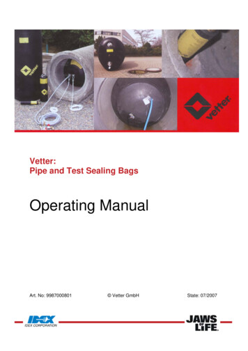
Sealing ElementsTechnical Handbook O-rings12. O-ring Gland DesignThe most effective and reliable sealing is generallyprovided with the diametrical clearance as shown inTable 3.B-1a. The maximum allowable gaps are indicated for 70 hardness O-rings with different crosssections without back-ups for reciprocating and staticseals. These values correspond to a pressure of ca.1200 PSI (80 bar) (8 MPa) at 70 F (21 C). Whengreater clearances occur, fig. 1-21 indicates conditions where O-ring seals may be used - depending onthe fluid pressure and O-ring hardness. [See Table3.B-1a]Selection of O-ring OD and IDWhen selecting an O-ring ID (or an O-ring OD), consider first the stretch that will be included on theO-ring on final assembly. O-rings and grooves shouldbe dimensioned to give acceptable strech both onassembly and on pressurization. Table 3.C gives theO-ring/groove common dimensions for good sealingpractice for several groove types.For flange-type grooves with internal pressure, designthe system so that on assembly, the O-ring OD seatsonto the OD of the groove. Make sure that the O-ringOD is not larger than the groove OD to ensure a goodseal. This will ensure best possible seal fit, and minimize stretch on assembly.If the pressure direction is reversed, make surethat the O-ring ID seats onto the ID of the groove.Effectively, this ensures that when the system is pressurized the O-ring does not stretch.In the case of a trapezoidal, or other irregularlyshaped groove, first look at the pressure directionand then decide on how to minimize stretch. For thecase of a trapezoidal section groove use the groovecentroid as a base for determining a suitable O-ringID. This ensures easy assembly and normally smallstretch. In any case, initial stretch on assemblyshould not exceed 3%.Cross 4,0-6,0 .275 6,0Max. clearance 70 Shore Ainchmm.002 - .0040,05 - 0,1.002 - .0050,05 - 0,13.002 - .0060,05 - 0,15.003 - .0070,07 - 0,18.004 - .0100,1 - 0,2510.500 (700)9.000 (600)4.500 (300)3.000 (200)Pressure psi (bar)Note: for silicone and fluorosilicone O-rings reduce allthe clearances shown by 50%.The diagram (fig. 1-21) gives a guide to the relationbetween hardness, pressure, clearance, and extrusion. This figure is based on NBR O-rings with a crosssection of .139 inch (3,53 mm) without back up rings.When there is risk for extrusion use contoured hardrubber or plastic back-up rings. The results are basedon tests at temperatures up to 70 C.Table 3.B-1a Gland clearance in relation to hardnessand O-ring cross section2.000 (140)1.500 (100)extrusion1.000 (70)825 (55)600 (40)90 Sh.A450 (30)300 (20)70 Sh.Ano extrusion225 (15)150 (10)inchmm.0100,25.0200,5.0300,7.0401,0Total Diametral Clearance GapFig. 1-21Table 3.C - O-ring/groove common dimensions for good seal fitSeal typePressure dal flange groovePiston rod/housingCommon seal/groove dimensionsODIDIDCentroidID137All the information in this documentation has been compiled with the greatest of care.Despite this we can bear no responsibility whatsoever for any errors present in the documentation. The recommendations are intended as guidelines.www.eriks.info
Sealing ElementsTechnical Handbook O-rings12. O-ring Gland Design12 A. Gland Design Static Axial ApplicationGland Design for Static Application for O-rings with Axial SqueezeBreak corners app. R .005 (0,15)Surface Finish Xgroove top and bottom :for liquidsX 32 micro inches (0.8 µm Ra)for vacuum and gasesX 16 micro inches (0.4 µm Ra)groove sides:X 63 micro inches (1.6 µm Ra)PressureoutsidePressureinsidex surface finish µm Ragroove depth is incl. gapFig. 1-27 aFig. 1-26Table AS C1 - Gland Dimensions (inches) Industrial Face or Flange TypeO-ringCross 101/4.275Gland DepthStatic SqueezeAxial Static In.for Face SealsEActual 016Groove 342/.362Vacuum & Groove 35These dimensions are intended primarily for face type seals and normal temperature applications.138All the information in this documentation has been compiled with the greatest of care.Despite this we can bear no responsibility whatsoever for any errors present in the documentation. The recommendations are intended as guidelines.www.eriks.info
Sealing ElementsTechnical Handbook O-rings12. O-ring Gland DesignTable 3.C-1 Gland Dimensions Static Application-Face Seal Glands-MetricGland Design for Static Application forO-rings with Axial SqueezeFace Seal Glands (METRIC)O-rings which are compressed axially ina static application are also called flangeseals. (see fig. 26 and 27).Surface Finish Xgroove top and bottom :for liquidsX 32 micro inches (0.8 µm Ra)for vacuum and gasesX 16 micro inches (0.4 µm Ra)groove sides:X 63 micro inches (1.6 µm Ra)PressureoutsidePressureinsideFig. 1-26Break corners app. R .005 (0,15)x surface finish µm Ragroove depth is incl. gapFig. 1-27 aWEFO-ring cross sectionGland DepthGroove WidthDiam.Tol. /-LiquidsVacuum/ISO 3601-1BTol. -0/ Tol. -0/ 0,13gasesmm0,900,080,680,021,301,101,0 - 25 - 500,081,130,022,201,801,60 - 1,630,081,200,032,351,901,78 - 300,322,1520,8020,00,2*17,000,324,6523,10RGroove * not defined in ISO 3601/1139All the information in this documentation has been compiled with the greatest of care.Despite this we can bear no responsibility whatsoever for any errors present in the documentation. The recommendations are intended as guidelines.www.eriks.info
Sealing ElementsTechnical Handbook O-rings12. O-ring Gland Design12 B. Gland Design Static Radial ApplicationGland Design for Static Application for O-rings with Radial SqueezeIndustrial Radial Glands INCHESSurface Finish Xgroove top and bottom :for liquidsX 32 micro inches (0.8 µm Ra)Break corners app. R .005 (0,15)for vacuum and gasesX 16 micro inches (0.4 µm Ra)groove sides:X 63 micro inches (1.6 µm Ra)x surface finish µm RaFig. 1-28groove depth is incl. gapFig. 1-27 aTable AS.C2 Gland Dimensions Static Seals - Industrial Radial Applications (Inches)O-ringGland Depth.StaticClearanceCross sectionRadial StaticSqueeze forDiametralWERadial SealsNominal ActualActual%Standard1/16.070.050/.052.015/.023 22/32 *.002 min. .093/.0983/32.103.081/.083.017/.025 17/24 *.002 min. .140/.1451/8.139.111/.113.022/.032 16/23 *.003 min. .187/.1923/16.210.170/.173.032/.045 15/21 *.003 min. .281/.2861/4.275.226/.229.040/.055 15/20 *.004 min. /.025.020/.035.020/.0351. Total Indicator Reading between groove and adjacent bearing surface.2. These groove dimensions are for compounds that free swell less than 15%. Suitable allowances should be made for higher swell compounds.*For max. allowable cleareance, refer to fig. 22 to determine value based upon pressure requirement and compound hardness.* Maximum clearance should be reduced by 1/2 for compounds exhibiting poor strength such as silicone and fluorosilicone.Male plug dimensions and female throat (bore) dimensions must be calculated based upon maximum and minimum clearance gaps.140All the information in this documentation has been compiled with the greatest of care.Despite this we can bear no responsibility whatsoever for any errors present in the documentation. The recommendations are intended as guidelines.www.eriks.info
Sealing ElementsTechnical Handbook O-rings12. O-ring Gland DesignTable 3.C-2 Gland dimensions Static Application-Industrial Radial Seals, metric12 B. Gland Design Static RadialApplicationGland Design for Static Application forO-rings with Radial SqueezeIndustrial Radial Glands INCHESSurface Finish Xgroove top and bottom :for liquidsX 32 micro inches (0.8 µm Ra)for vacuum and gasesX 16 micro inches (0.4 µm Ra)groove sides:X 63 micro inches (1.6 µm Ra)Fig. 1-28Break corners app. R .005 (0,15)x surface finish µ Ragroove depth is incl. gapFig. 1-27 aWES Diametr. F GrooveR GrooveMax.O-ring cross sectionGland DepthClearanceWidthRadius EccentricityDiam.Tol. /-Tol.ISO 3601-1BTol. -0/ Tol. -0/ 0,13mm0,900,080,650,020,11,200,21,0 - ,21,25 - ,21,500,081,090,020,12,000,21,60 - 1,630,081,160,030,12,100,21,78 - 130,130,130,130,130,130,130,130,130,13141* not defined in ISO 3601/1All the information in this documentation has been compiled with the greatest of care.Despite this we can bear no responsibility whatsoever for any errors present in the documentation. The recommendations are intended as guidelines.www.eriks.info
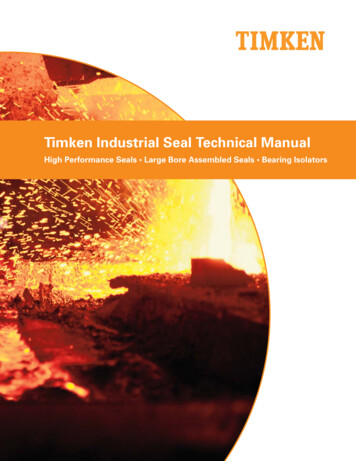
Sealing ElementsTechnical Handbook O-rings12. O-ring Gland Design12 C. Gland Design Dovetail GroovesGland Design for a Static Application; for O-rings in DovetailGrooves, INCHESDovetail grooves are used to hold the O-ring in place duringinstallation or maintenance. This groove design is relativelyuncommon as it is expensive to machine and should not be usedunless absolutely required.The dovetail groove construction is only recommended forO-rings with cross sections of .139 inch(3,53 mm) and larger.x surface finish in µm RaFig. 1-30Surface Finish Xgroove top and bottom :for liquidsX 32 micro inches (0.8 µm Ra)for vacuum and gasesX 16 micro inches (0.4 µm Ra)groove sides:X 63 micro inches (1.6 µm Ra)Table AS.C3 Gland Dimensions Dovetail Grooves, InchesO-ringGland Depth. SqueezeCross 4163/8.375.315/.31916Groove Widthto Sharp 235.315/.319Groove .090Radius "R2" is critical. Insufficient radius will cause damage to the seal during installation, whileexcessive radius may contribute to extrusion. R2 is size radius, R1 is machining radius.142All the information in this documentation has been compiled with the greatest of care.Despite this we can bear no responsibility whatsoever for any errors present in the documentation. The recommendations are intended as guidelines.www.eriks.info
Sealing ElementsTechnical Handbook O-rings12. O-ring Gland Design12 C. Gland Design Dovetail GroovesGland Design for a Static Applicationfor O-rings in Dovetail Grooves, METRICDovetail grooves are used to hold theO-ring in place during installation ormaintenance. This groove design is relatively uncommon as it is expensive tomachine and should not be used unlessabsolutely required.The dovetail groove construction is onlyrecommended for O-rings with biggercross sections, .139 inch(3,53 mm) and bigger.Surface Finish Xgroove top and bottom :for liquidsX 32 micro inches (0.8 µm Ra)for vacuum and gasesX 16 micro inches (0.4 µm Ra)groove sides:X 63 micro inches (1.6 µm Ra)Table 3.C-3 Gland Dimensions Dovetail Grooves, metricWEO-ringGrooveCross SectionDep
Despite this we can bear no responsibility whatsoever for any errors present in the documentation. The recommendations are intended as guidelines. www.eriks.info Technical Handbook O-rings Save time calculating and designing O-ring grooves and verify the O-ring sealing perform