Transcription
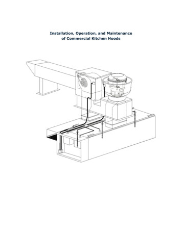
InstallationGuideVersion 2.0
Installation GuideDISCLAIMERNo part of this publication may be stored, reproduced or copied without prior written permission from IMO Precision Controls Ltd.The material furnished in this document is believed to be accurate and reliable however, IMO Precision Controls Ltd assumes no responsibility forthe use of this material. IMO Precision Controls Ltd reserves the right to make changes to the information contained at any time without prior notice.All products and company names mentioned in this manual are trademarks or registered trademarks of their respective holders.The information contained herein is subject to change without prior notice for improvement.FCCThis equipment has been tested and verified to be in compliance with the limits for FCC CFR47 part 15.107 Class B - Conducted Emissions andFCC CRF47 Part 15.109 Class B - Radiated Emissions, to provide reasonable to provide reasonable protection against harmful interference forunlicensed premises. This equipment generates and can radiate radio frequencies, and if not installed in accordance with the instructions, maycause interference with radio communications; should such interference occur then consider relocation of the product in order to increase theseparation between the equipment.Alterations not approved by the compliance authority may void the user’s authority to operate this equipment.CONTACT DETAILSPlease contact the below concerning technical questions about this product:United Kingdom020 8452 6444imo@imopc.comAustralia / New Zealand08 9302 5246support@imopacific.com.auCanada905 799 9237imo-ca@imopc.comUSA678 679 7110imo-usa@imopc.comFrance0800 912 712imo-fr@imopc.comItaly800 930 872imo-it@imopc.comSouth Africa021 551 1787info@imopc.co.za 44 (0)20 8452 6444imo@imopc.comRest Of The WorldSAFETY SYMBOLSPlease contact the below concerning technical questions about this product:-!Warning - Failure to heed this the information indicated by this symbol may lead to dangerous conditions, possibly resulting in deathor serious bodily injury.Caution - Failure to heed this the information indicated by this symbol may lead to dangerous conditions, possibly resulting in minoror light bodily injuries and/or substantial property damage.inInformation - Denotes important information about safety issues.Note - Denotes additional information.
Installation GuideSAFETY INSTRUCTIONS!The FireRaptor is an electrical product and should only be installed by a suitably qualified person, in accordance with local regulations.!When modifying and existing installation, isolate the inverter from the PV array by turning OFF the DC isolator / switch disconnect orturn OFF the inverter and the AC switch.!PV Panel input and output connectors are not environmentally sealed until they are mated. Disconnected connectors should beplugged into an appropriate mating part or used with suitable watertight caps.!FireRaptor DC input and output connectors are not environmentally sealed until they are mated. Disconnected connectors should beplugged into an appropriate mating part (Tyco 282104-1 & 2pcs 282081-1 provided in FRS-ESW1/ FRS-ESW1-F / FRS-ESW1-K /FRS-ESW1-FK) or used with suitable watertight caps.!Incorrect connections to the FireRaptor may cause failure.CAUTIONSInstallation of the IMO FireRaptor without ensuring compatibility of the module\inverter connectors with the FireRaptor connectorsmay be unsafe and cause operational problems. For mechanical compatibility of the modules\inverter and the FireRaptor, use identicalconnectors from the same manufacturer on both the FireRaptor and modules, or obtain verification that the connectors to be usedare compatible.If the IMO FireRaptor is to be mounted directly to the PV frame or module, obtain guidance from the module manufacturer regardingit’s location and also verify the impact on the module warranty.INTRODUCTIONThe IMO Precision Controls FireRaptor product is a Rapid Shut Down System for connection to PV panel arrays in order to achieve compliance to2014 NEC 690.12 and the forthcoming 2017 NEC 690.12.The FireRaptor automatically shuts down array output to the PV inverter when it detects a temperature in excess to 85 C (FRS-01) and 92 C(FRS-02).The FireRaptor can be installed without any set-up and with any string inverter as its functionality is completely independent. “Plug & Play”style installation using industry standard connectors makes the IMO FireRaptor suitable for new installations as well as retro-fit; and its mainspowered independent DC power supply and emergency switch unit allows flexibility for positioning for user convenience giving Manual EmergencyShutdown, as well responding to local or area grid shutdown.PARTSFRS-01FireRaptor Rapid Shutdown System UnitFRS-02FireRaptor Rapid Shutdown System Unit with Fire Monitoring & Integration OptionsFRS-ESW1Emergency Rapid Shutdown Switch Unit (for FRS-01) - includes 24 VDC power supplyFRS-ESW2Emergency Rapid Shutdown Switch Unit (for FRS-02) - includes 24 VDC power supplyFRS-ESW1-KEmergency Rapid Shutdown Switch Unit with Key Lock (standard key) for FRS-01 - includes 24 VDC power supplyFRS-ESW2-KEmergency Rapid Shutdown Switch Unit with Key Lock (standard key) for FRS-02 - includes 24 VDC power supplyFRS-ASW1Auxiliary Emergency Rapid Shutdown Switch Unit (excludes 24 VDC power supply)FRS-ASW1-KAuxiliary Emergency Rapid Shutdown Switch Unit with Key Lock (excludes 24 VDC power supply)
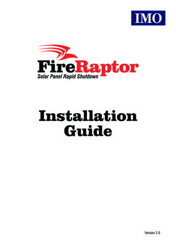
Installation GuideINSTALLATION & CONNECTIONOne FireRaptor will control two solar panels and for compliance with 2017 NEC it should be mounted within the array boundary of the two panels,where the two panels are no greater than 1’ (foot) /30cm apart from each other.Determine the mounting location of the FireRaptor (FRS-01 / FRS-02) and fix as shown below.Solar PanelMounting FrameFlat WasherFireRaptorStar WasherMounting FrameBracket7mmFireRaptor(¼” or M6screws & washer)14mmKeyholeMounting Method 1Mounting Method 2Do not drill though the FireRaptor as this will damage the unit and prevent operation.Mounting Method 1 offers ease of fixing whilst Mounting Method 2 can be used where more effective use of the FireRaptor’s onboard temperaturesensing is required, by placing the FireRaptor in position against the underside of the PV panel (or the surface where the temperature needs to besensed). Once mounted ensure that the FireRaptor is secure.nThe FireRaptor is housed in a plastic enclosure therefore grounding of the product is unnecessary.Connect the two PV panels in series (typical wiring example below). Connect the array Positive ( ) output connector to the FireRaptor Positive ( )input connector. Connect the array Negative (-) output connector to the FireRaptor Negative (-) input connector.IMOFireRaptorInPWROutPowerPanels! PAN-PanelsSTG -StringFireRaptor External WiringStringWarning – Ensure that you have identified the inputs correctly. The FireRaptor input cables are the shorter ones.Connect the FireRaptor’s two output cables to the DC isolator/Solar Inverter ensuring that the correct polarity is maintained throughout the electricalwiring.iThe FireRaptor is OFF giving no array output until such time as the external DC power supply is energised and the Emergency Switchis in its non-activated position.
Installation GuideThe Emergency Rapid Shutdown Switch Unit (FRS-ESW1 / FRS-ESW2 / FRS-ESW1-K / FRS-ESW2-K), hereafter referred to as FRS-ESW1, forinstallation; can be conveniently located anywhere for emergency access and is supplied with an internal 24VDC power supply to interface withthe FireRaptor units.Locate a convenient position for mounting the FRS-ESW1 unit ensuring that mains power connection is also available.L N24VDC AC MAINSInstallation Orientation24VDC24VDCACAC MAINSMAINSFRS-ESW1POWER SUPPLYSWITCHDIN Term.FUSEDIN Term.SWITCHDIN Term.DIN Term.TOPPOWER SUPPLYRemove the FRS-ESW1 cover and insert cable glands into position, ensuring that the sealing washer is between the main gland body and the outerenclosure surface, then tighten the securing/locking nut. Take care not to damage the switch, DIN terminals, power supply or wiring containedwithin the FRS-ESW1 enclosure.L N24VDC24VDCACAC MAINSMAINSFRS-ESW2Using appropriate fixings attach the FRS-ESW1 unit vertically to the chosen surface.Mounting the FRS-ESW1 non-vertically will invalidate warranty.Connect the mains supply wire to the FRS-ESW1 power supply L and N (Live and Neutral) terminals using suitably rated 2-core cable (referTechnical Specifications section for electrical details) ensuring correct polarity of connections. Verify secureness of cables.inStrip AC mains wire length 4-5mm. Terminal tightening torque 0.5Nm (5lb-in).Power Supply can be unclipped from the DIN-Rail for easier wiring.Connect suitably rated 2x1mm2 cable, one wire to the black wired DIN terminal Negative (-) terminal and with other wire to the red wired DINterminal; this will be 24VDC Positive ( ) wire. Terminate the remote end with a Tyco SuperSeal 2-pole socket (female) ensuring correct polarityof connections [Tyco connector: pin 1 Positive ( 24VDC), pin 2 Negative (0VDC)].inStrip 24V DC wire length 10mm. DIN terminal tightening torque 0.5Nm (5lb-in).Do not remove wire links connected within the FRS-ESW1. Verify screw tightness in case of loosening in transit.Connect the Tyco SuperSeal 2-pole socket (female) to the FireRaptor plug (male).!Warning – Do not turn ON mains voltage until installation of FRS-ESW1 is completed and verified.
Installation GuideMULTIPLE INSTALLATIONSOne FireRaptor FRS-01 / FRS-02 will control two solar panels and by series connection of the FireRaptor, multiple solar panel pairs can beconnected to form a greater capacity system. The diagram below illustrates a typical example of a FireRaptor protected 2kW installation using eight250W solar panels and four FRS-01 FireRaptors.End cableavailableto order**Water ResistantEnd Stop*to String InverterIf the array has an odd number of panels, a single panel can be connected directly to the positive ( ) and negative (-) panel cables of the FireRaptor.Also, the IMO FireRaptor system allows for multi-level/multi-zone installation through the use of an Emergency Switch Enclosure (FRS-ESW1 plusFRS-AWS1) connected in series with the initial Emergency Rapid Shutdown Switch’s power supply Positive ( ) wire 24VDC.* Water resistant end stop - Insert the two red sealing plugs in to the Tyco Superseal plug (supplied) and connect tothe DC output connector of the last FireRaptor (FRS-01) in the series installation. If only a single FireRaptor (FRS-01) isused then this part is still used to seal the DC output connector.** A 1.8m flying lead terminated at one end with a Tyco female connector is available to order under part number FRS-SIGCAB1.8-FOPERATIONUpon correct mounting and connection of the FireRaptor to the solar panels and the Emergency Shutdown Switch; and the turning ON of the mainssupply, the FireRaptor will be operational.1.2.Automatic Emergency Shutdowna)Should the FireRaptor (FRS-01) onboard temperature sensor detect an elevated ambient temperature rise in excess of 85 C thenthe FireRaptor will instigate an Automatic Rapid Shutdown thereby disabling the PV array output. Should the ambient temperaturethen drop back to below 85 C, the FireRaptor will re-engage the PV array output.b)In the event that the temperature exceeds 92 C then the FireRaptor (FRS-01) will only re-engage the solar panels by a manualreset done via the Emergency Shutdown Switch (refer to point 4a below).c)With FireRaptor FRS-02, should the onboard temperature sensor detect an elevated temperature in excess of 92C then, likepoint (a), the FRS-02 will instigate an Automatic Rapid Shutdown thereby disabling the PV array output. Operation will only berecommenced by a manual reset done via the Emergency Shutdown Switch (refer to point 4b below)Manual ShutdownUpon the user operating the red push button switch located in the Emergency Switch Enclosure the FireRaptor performs a RapidShutdown, disabling the PV array output.3.Utility ShutdownShould there be a necessity by the emergency services for local or area utility grid shutdown the IMO FireRaptor will perform aRapid Shutdown disabling the PV array output.4.Reseta)On the occurrence of operation 1b (above) where the temperature exceeds 92 C, once the area is deemed safe, the FireRaptorFRS-01 is reset by operating the Emergency Shutdown Switch and then releasing this switch.b)Upon occurrence of operation 1c (above), the installation and FireRaptor FRS-02 units must be checked by a competent person.Once the area is deemed safe then the FireRaptor is reset by replacement of the appropriate fuse within the FRS-ESW2/FRS-ESW2-K and then operating the Emergency Shutdown Switch and then releasing this switch.
Installation GuideiThe Emergency Shutdown Switch is a typical “one push” large red emergency push button which requires an anti-clockwise twist torelease.nThe FRS-ESW1 and FRS-ESW1-K includes an LED status indicator which when used with FRS-01 signifies 24VDC power status (ON)or power loss (OFF).nThe FRS-ESW2 and FRS-ESW2-K includes an LED status indicator which when used with FRS-02 signifies 24VDC power status (ON),or power loss or trip (OFF).TECHNICAL SPECIFICATIONFRS-01 FireRaptor UnitEmergency Shutdown CableDC Power Supply*2x1mm2 cable Tyco SuperSeal 2-pole plug/connector (male/female)24VDC suitable for up to 20 FireRaptor units (40 panels)Maximum Input Power700W (350W per panel)Maximum Input Voltage150V (75V per panel)Maximum Input Current12AMaximum System VoltageInput Protection1500VOver voltage & transient voltage supressionMaximum Output Current12A (99.5% efficiency)Breakdown Voltage1500VAC for 1 minuteMaximum Output Voltage150V (75V per panel)Output ProtectionAmbient Operating TemperatureIP Class ProtectionCasingWeight (without cables)Over voltage, over current & transient voltage suppression-30 C to 95 C IP68 (designed to comply with NEMA 4X)Flame retardant Polycarbonate - UL94-V0 (f1)300gPanel Cable Length120mmString & Signal Cable Length1800mmStandard ComplianceEN 61000, EN 61646, EN 61215, IEC 62716 draft C (NH3 resistant),VDE-AR-E 2100-712, BS 7671-712FRS-ESW1 Power Supply**Rated Input VoltageRated Input Current (at IO nom)Rated Input FrequencyInput Fuse90-264VAC200mA (Vi 115VAC)/ 135mA (Vi 230VAC)47-63HzT1A (250VAC)Rated Output Voltage24VDCRated Output Current420mARated Output Power10WAmbient Operating Temperature-30 C to 60 C* FRS-ESW1/FRE-ESW1-K Rapid Shutdown Switch can be upgraded to suit larger installations. Contact IMO for more details.** FRS-ESW2/FRS-ESW2-K includes a 250V 500mA F fuse, replace only with fuse of the specified type, current and voltage. Contact IMO for more details.
Installation GuideTROUBLESHOOTINGProblemPossible CausePossible SolutionPanel (pair) voltage is 0VNo mains supply(LED OFF)Check area utility operationalCheck mains ONCheck mains fusePV Inverter input 0VFRS-ESW1 power supply failure(LED OFF)Check mains voltage between L & N marked terminalsFRS-ESW1 switch activatedTurn red actuator anti-clockwise to release buttonNo FRS-ESW1 switch output(LED OFF)Check 24VDC between switch out terminal & PSU – markedterminalBroken cable(LED OFF)Check 24VDC between terminals of remote Tyco SuperSealconnector (pin 1 24VDC\pin 2 0VDC)PV array not connectedCheck all PV to FRS-01 / FRS-02 input connectionsIncorrect FRS-01 / FRS-02 polarityconnectionCheck PV array Positive ( ) goes to FRS-01 / FRS-02Positive ( ) and PV array Negative (-) goes to FRS-01 /FRS-02 Negative (-)No FRS-01 / FRS-02 outputReplace FRS-01 / FRS-02No DC isolator (if fitted) inputCheck FRS-01 / FRS-02 output connectionsCheck 24VDC between & - marked terminalsCheck DC inputs to isolatorString voltage too lowDC Isolator (if fitted) OFFTurn DC Isolator ONIncorrect FRS-01 / FRS-02 polarityconnectionCheck all PV array Positive ( ) go to FRS-01 / FRS-02Positive ( ) and PV array Negative (-) go to FRS-01 /FRS-02 Negative (-)In the occurrence of a fire IMO recommend that all elements of the FireRaptor Rapid Shutdown system be assessed for operational suitability bya competent person prior to re-energising.IMO Precision Controls Ltd. The Interchange, Frobisher Way, Hatfield, Herts AL10 9TG UKTel: 44 (0)20 8452 6444 Fax: 44 (0)20 8450 2274Information correct at time of print. Errors & omissions excepted.www.imopc.com
The IMO Precision Controls FireRaptor product is a Rapid Shut Down System for connection to PV panel arrays in order to achieve compliance to 2014 NEC 690.12 and the forthcoming 2017 NEC 690.12. The FireRaptor automatically shuts down array output to the PV inverter when it detects a