Transcription
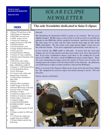
SolarEdge Quick Installation Guide – North AmericaFor full installation and safety details, you must refer to the SolarEdge Installation Guide. Make sure you read, fully understand and follow the detailedinstructions in the SolarEdge Installation Guide prior to each installation. Failure to do so could result in injury or loss of life and damage or destruction of theequipment.Connecting Power Optimizers to ModulesMount the power optimizers in a shaded location near the PV modules, on the structure or racking to which the module is attached, using both mounting holes.If possible, avoid mounting power optimizers in locations where they will be exposed to direct sunlight.Make sure that each power optimizer is positioned within reach of each module’s cables.1Attach each power optimizer to the rack using the 5/16'' or 1/4'' bolts, nuts and washers.2Use the following methods to ground the power optimizer: For mounting on a grounded metal rail:Use the provided 5/16'' stainless steelgrounding star washer between therailing and the flat side of the mountingbracket.The grounding washer should breakthrough the anodize coating of the railingto ensure low resistive connection. Applytorque of 9.5 N*m / 7 lb*ft.2NA Series Power Optimizer3NA Series Power OptimizerStar washerStar washerFor mounting on rails with sliding nutfasteners, or an un-grounded structure(such as a wooden structure): Connect anequipment-grounding conductor to thegrounding terminal according to thesupplied instructions (the terminal shouldbe purchased separately)1. The groundingterminal accepts a wire size of 6-14 AWG,and must be sized for equipmentgrounding per NEC 250.122 requirements.Tighten the screws connecting the poweroptimizer to the frame and the groundingterminal screw. Apply torque of 9.5 N*m /7 lb*ft.Optional GroundingTerminal3To benefit from the physical mapping of the installation in the SolarEdge Monitoring Portal, record each power optimizer’s serial number and location:Peel off its removable barcode sticker and stick it on the mapping template, or scan the barcode with the SolarEdge iPhone Site Mapper app. Upload themap to the SolarEdge website, using the site registration form.4Connect the Plus ( ) output connector of the moduleto the Plus ( ) input connector of the poweroptimizer.5Connect the Minus (-) output connector of themodule to the Minus (-) input connector of thepower optimizer.Output - - -InputOutput -Input - Connect to Module1For additional information, refer to ate-dcd-c-grounding-lug.pdf.1Input
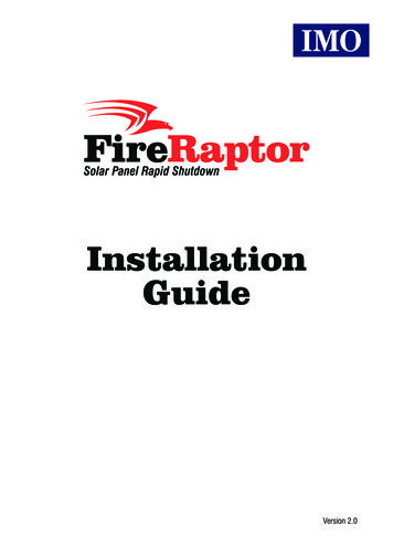
MAN-01-00025-2.0Connecting Power Optimizers to a String1Connect the power optimizer outputs in series: Connect the Minus (-) output connector of thestring’s first power optimizer to the Plus ( ) output connector of the string’s second poweroptimizer. Connect the rest of the optimizers in the string in the same way. 2The minimum and maximum string length should be according to the power optimizerdatasheet.Strings DO NOT have to be of equal length.Verify proper connection of power optimizers: Before the inverter is turned ON, each poweroptimizer produces 1V safety-voltage, which should be verified for each string using a voltmeter.The voltage on a string is the number of modules multiplied by 1V, with a deviation of 10mV permodule. Make sure the modules are exposed to sunlight during this process.NOTE:If several strings are connected in parallel, verify voltage for each string separatelyInstalling the Inverter1Make sure that the inverter ON/OFF switch at the bottom of theinverter is switched OFF before and during the installation, and thatthe AC circuit breaker is OFF.2Install the mounting bracket on the wall with the U-shapedindentations facing up.3Hang the inverter on the bracket. Secure it to the bracket using thetwo supplied screws. Make sure to leave clearance areas in orderto cool the inverter: 8" above, at least 15" below (leaving sufficientclearance for conduits entering from the bottom) and 4" on eitherside.4Mounting Bracket OrientationBracket ScrewUse an M6 Allen key to open the inverter's six cover screws andremove the cover.Installing the AC/DC Safety Switch1Make sure the switch is in the OFF position.2Use an M6 Allen key to open the AC/DC Safety Switch cover screws and remove the cover.3Open the required knockout pair (bottom, back or sides of the enclosure, sized ¾'' or 1'') according to theconduits used in the installation.Loosen thesescrews4Use the supplied template to mark the drilling hole positions, drill the holes and firmly mount thebracket to the surface.PaperTemplate5Unscrew the two nuts at the conduit ends and position the switch below the inverter. From theinside of the inverter, grab the AC and DC wires extending from the switch conduits.ACDC6Attach the safety switch to its bracket using the four supplied screws andslightly close the screws. Do not tighten the screws.Conduit Nuts7Securely screw the two conduit nuts onto the conduit ends in the inverter.8Securely tighten the four bracket screws with a torque of 9 N*m/ 6.6 lb*ft.2
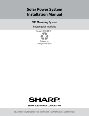
MAN-01-00025-2.0Connecting the Switch to the Inverter1Connect the DC as follows: Connect the red wire to any of the DC terminals in the inverter.Connect the black wire to any of the DC- terminal in the inverter.Single Phase Inverter DC TerminalsDC (Red wire)DC(Black wire)DC (Red wire)2Three Phase Inverter DC TerminalsDC(Black wire)Depending on the inverter type (single phase or three phase), connect the AC, as follows:Single Phase InverterWire colorConnect to terminalWhiteBGreen/yellowCRedDBlackEA BThree Phase InverterWire color/labelConnect to terminalBlack / L1L1Black / L2L2Black / L3L3Green/yellowGroundWhiteNL1 L2 L3CD EN Ground3Tighten the screws of each terminal with a torque of 1.2-1.5 N*m / 0.88-1.1 lb*ft.4Verify that there are no unconnected wires at the output of the AC/DC Safety Switch and that the unused terminal screws are tightened.Connecting the Strings and the AC to the AC/DC Safety SwitchThe AC/DC Safety Switch connections are shown below:DC SideConduitDCConnectionsDC SideConduitAC SideConduitACConnectionsDCConnectionsAC SideConduitAC Groundand NeutralConnectionsAC gDCD-1PH-US-C (Safety Switch for single phase inverter)DCD-3PH-US-S3-A (Safety Switch for three phase inverter)3
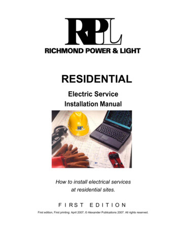
MAN-01-00025-2.01Connect to the AC Grid:WARNING!Connect the equipment grounding before connecting the AC wires to the AC terminal block.Veillez à relier le conducteur de PE (la terre) avant de connecter les fils CA au bornier CA. 2Insert the AC conduit into the AC-side knockout that was opened.Single phase inverter - Connect the wires to the appropriate terminal blocks, according to the label in theswitch. Connect the grounding wire first. Use a standard straight-bladed screwdriver to connect the wires tothe spring-clamp terminals.Three phase inverter - Connect the Ground and Neutral wires to the terminal blocks in the AC side of the switch.Connect the line wires to the appropriate connectors according to the label located in the switch.-L1L2L3Verify that there are no unconnected wires.Connect the strings: Insert the DC conduit into the DC-side knockout that was opened.Connect the DC equipment ground conductor to the equipment grounding terminal block.NOTE:Functional Electrical Earthing of DC-side negative or positive is prohibited because the inverter has no transformer. Earthing of moduleframes and mounting equipment (equipotential bonding) is required per NEC. Single phase inverter - Connect the DC wires from the PV installation to the DC and DC- terminal blocks, according to the labels on theterminals. Use a standard straight-bladed screwdriver to connect the wires to the spring-clamp terminals.Three phase inverter - Connect the DC wires from the PV installation to the DC and DC- terminals, according to the labels in the switchCAUTION:Ensure that the wire is connected to the terminal and that the - wire is connected to the - terminal.Veillez à ce que le câble soit connecté au terminal et que le câble - soit connecté au terminal.3Two strings may be connected in parallel to the two DC input pairs of the switch. If more than two strings are required, they can be connected in parallelin an external combiner box before connecting to the switch.NOTE:If more than two strings are connected each should be properly fused on both DC and DC- according to NEC690.35(B).Setting up CommunicationTwo communication glands are used for connection of the various inverter communication options. Each gland has three openings. The table below describesthe functionality of each opening. Unused openings should remain sealed.Gland#OpeningFunctionalityCable Size(diameter)1(PG 16)One smallExternal antenna cable2-4 mmTwo largeEthernet connection(CAT5/6) or ZigBee4.5-7 mmAll threeRS485, power reduction2.5-5 mm2 (PG 13.5)The inverter has either an RJ45 or an 8-pin terminal block connector for Ethernet communication, and a 9-pin terminal block connector for RS485/RS232communication.1To create an Ethernet (LAN) connection: Remove the seal from one of the two large openings in communication gland #1 and insert an Ethernet CAT5/6 cable through the opening.Mini USBRS232/RS485Ethernet (RJ45)Mini USBRS232/RS485Ethernet4
MAN-01-00025-2.0 If the inverter has an 8-pin terminal block connector for Ethernet communication:a. Pull the connector out, loosen the screws, except for that of pin G and insert the ends of the wires into the pins according to the following table:Terminal BlockRJ45 Pin #Color11White/green22Green33White/Orange44 and 5Blue White/Blue66Orange77 and 8Brown White/BrownSAluminum shieldG-unconnectedb. Tighten the screws of the Ethernet terminal block.c. Push the Ethernet terminal block firmly all the way into the communication board. If the inverter has an RJ45 connector for Ethernet communication, use either a pre-crimped cable or the supplied kit for RJ45, and connect asfollows:a. Insert the cable through gland no. 1.b. Insert the eight wires into the RJ45 connector, as described below.c. Use a crimping tool to crimp the connector.d. Connect the Ethernet connector to the RJ45 plug on the inverter's communication board 2PinWire ue6Orange7White/Brown8BrownConnect the cable’s RJ45 connector to the RJ45 port of the Ethernet switch or router.To create an RS485 connection: 3For the switch/router side, use a pre-crimped cable or use a crimper to prepare an RJ45 communication connector: Insert the eight wires intothe RJ45 connector.Remove the seal from one of the openings in communication gland #2 and insert the wire throughthe opening.Pull out the 9-pin RS485/RS232 terminal block connector, and loosen the screws of pins B, A and Gon the left of the RS-485 terminal block.Insert the ends of wires into the G, A and B pins. Use four- or six-wire twisted pair cable for thisconnection. You can use any color wire for each of the A, B and G connections, as long as the samecolor wire is used for all A pins, the same color for all B pins and the same color for all G pins.If creating an RS485 bus - connect all B, A and G pins in all inverters.Tighten the terminal block screws, and push it firmly all the way into the communication board.RS485-2 (not in use)GABTerminate the first and last inverters in the chain by switching a termination dipswitch inside the inverter to ON (move the switch to the top).The switch is located on the communication board and is marked SW7.To connect to the server, designate a single inverter as the connection point between the RS485 bus and the SolarEdge Monitoring Server. Thisinverter will serve as the master inverter. Connect the master to the SolarEdge Monitoring Server via one of the communication options.To use the optional ZigBee communication option, refer to the ZigBee device user manualsClosing the AC/DC Safety Switch and Inverter Covers1Attach the switch cover and secure it by tightening the four screws with a torque of 1.2 N*m / 0.88 ft*lb:2Move the switch to the ON position.3Verify that the inverter is configured to the proper country. If it is not, it may display a voltage or frequency error at first startup. Incorrect configurationwill not damage the inverter, but it will not operate normally unless properly configured. If additional country setting or inverter configuration isnecessary, perform them before closing the inverter, as described in Steps 1 through 6 of the next section.4Attach the inverter cover and secure it by tightening the screws with a torque of 3.9 N*m/ 2.9 lb*ft. For proper sealing, first tighten the corner screwsand then the two central screws.5
MAN-01-00025-2.0Commissioning and Activating the Installation1Verify that the inverter ON/OFF switch is OFF.2Activate the inverter according to the activation instructions supplied with the inverter.3Turn ON the AC breaker.WARNING!High AC voltage is present in the inverter – HANDLE WITH CARE!.Une haute tension CA est présente dans l’onduleur – MANIPULEZ AVEC PRECAUTIONS !4Turn ON the AC/DC Safety Switch. If an additional external DC switch is installed between the power optimizers and the inverter(s) then turn it ON. Amessage similar to the following appears on the inverter LCD panel:V a c [ v ]V d c [ v ]2 4 0 . 71 4 . 1P O K :0 0 0 / 0 0 05P a c [0 S OO Fw ]. 0K FVerify the following in the LCD display: Vac: Specifies the grid voltage.Vdc[V]: The DC input voltage of the longest string connected to the inverter. There should be a safety voltage of 1V for each power optimizerin the stringPac[W]: AC power production. At this stage, it should be 0w.P-OK: Specifies the number of properly connected power optimizers.S-OK: Indicates the status of the connection to the SolarEdge monitoring portal (if connected).6Configure the country code, display language and communication configuration using the inverter user buttons and LCD. The buttons are located justabove the LCD and are numbered esc, 1, 2, 3/Enter from left to right. Enter the menus by pressing ENTER for five seconds and then inputting thepassword 12312312. To verify that the country code is set to USA, select Country from the main menu, press Enter and select USA . In the next menuthat appears, select the desired AC grid configuration.7Close the inverter cover.WARNING!Before proceeding to the next step, make sure that the cover is closed! High DC Voltage will be present in the inverter following the next step!Avant d’entamer la prochaine étape, assurez vous que le couvercle est fermé ! Une tension DC très haute sera présente durant l’étapesuivante !8Make sure that the ON/OFF switch at the bottom of the inverter is OFF.9To pair the power optimizers to the inverter, press and hold down the inverter LCD button for about 10 seconds. The following message is displayed:KftRe e po rpoe ne m a ihatnoieil d i n gb u t t o nr i n g ,r e l e a s erm e n u . . .n g :3s e cKeep holding for 5 seconds until the following is displayed:T u r nP a i r i n gS w i t c hT oO n10 Turn the inverter ON within 5 seconds. If you wait longer than 5 seconds, the inverter exits the pairing mode. The following message is displayedindicating that the inverter is performing the pairing.P a i r i n gR e m a i n i n g[ s e c ] :1 8 011 Wait for the completion of the pairing (remaining seconds is 0). If pairing fails, an error is displayed. In this case, repeat the pairing steps.When pairing succeeds, the following message is displayed:P a i r i n gP a i r i n gC o m p l e t e d12 At the end of the pairing process, the system will start producing power. Verify on the LCD screen that the number next to P OK equals the number ofinstalled power optimizers. It may take up to 20 minutes until all the power optimizers are indicated.WARNING!After you turn ON the inverter ON/OFF switch, the DC cables carry a high voltage and the power optimizers no longer output a safe 1V output.Après avoir mis l'interrupteur ON/OFF de l'onduleur monophasé sur ON, les câbles DC portent une haute tension et les optimiseurs depuissance ne génèrent plus la tension de sécurité de 1V.WARNING!After you turn OFF the inverter ON/OFF switch, wait until the LCD indicates that the DC voltage is safe ( 50V), or wait five minutes beforeopening the cover or disconnecting the strings.Apres avoir tourné l’interrupteur ON/OFF sur OFF, attendre jusqu'à ce que l’écran LCD indique que la tension DC est sécurisée ( 50V) ouattendre cinq minutes avant d’ouvrir le couvercle ou de déconnecter les strings.Refer to the SolarEdge Installation Guide for detailed installationSupport and Contact Informationand safety instructions.If you have technical problems concerning our products, please contact us:USA and Canada: 1 (0) 877 360 5292Worldwide: 972 (0) 73 240-3118Fax: 1 (0) 530 273-2769Email to ussupport@solaredge.com6
SolarEdge Quick Installation Guide – North America For full installation and safety details, you must refer to the SolarEdge Installation Guide. Make sure you read, fully understand and follow the detailed instructions in the SolarEdge Installation Gu