Transcription
Installation GuideBackup Interface for the SinglePhase Energy Hub Inverter withPrism Technologysuitable for use as service equipmentNorth AmericaVersion 1.1
DisclaimersDisclaimersImportant NoticeCopyright SolarEdge Inc. All rights reserved.No part of this document may be reproduced, stored in a retrieval system ortransmitted, in any form or by any means, electronic, mechanical, photographic,magnetic or otherwise, without the prior written permission of SolarEdge Inc.The material furnished in this document is believed to be accurate and reliable.However, SolarEdge assumes no responsibility for the use of this material. SolarEdgereserves the right to make changes to the material at any time and without notice. Youmay refer to the SolarEdge web site (https://www.solaredge.com/us/) for the mostupdated version.All company and brand products and service names are trademarks or registeredtrademarks of their respective holders.Patent marking notice: see https://www.solaredge.com/us/patentThe general terms and conditions of delivery of SolarEdge shall apply.The content of these documents is continually reviewed and amended, wherenecessary. However, discrepancies cannot be excluded. No guarantee is made for thecompleteness of these documents.The images contained in this document are for illustrative purposes only and may varydepending on product models.Backup Interface Installation Guide MAN-01-00729-1.11
2 FCC ComplianceFCC ComplianceThis equipment has been tested and found to comply with the limits for a Class B digitaldevice, pursuant to part 15 of the FCC Rules.These limits are designed to provide reasonable protection against harmful interferencein a residential installation. This equipment generates, uses and can radiate radiofrequency energy and, if not installed and used in accordance with the instructions,may cause harmful interference to radio communications. However, there is noguarantee that interference will not occur in a particular installation. If this equipmentdoes cause harmful interference to radio or television reception, which can bedetermined by turning the equipment off and on, you are encouraged to try to correctthe interference by one or more of the following measures:Reorient or relocate the receiving antenna.Increase the separation between the equipment and the receiver.Connect the equipment into an outlet on a circuit different from that to which thereceiver is connected.Consult the dealer or an experienced radio/TV technician for help.Changes or modifications not expressly approved by the party responsible forcompliance may void the user’s authority to operate the equipment.Backup Interface Installation Guide MAN-01-00729-1.1
3ContentsDisclaimersImportant NoticeFCC Compliance112Revision History4HANDLING AND SAFETY INSTRUCTIONSSafety Symbols Information55Chapter 1: OverviewStorEdge Solution ComponentsInstallation Equipment List667Chapter 2: Installing and Connecting the Backup InterfacePackage ContentsMounting the Backup InterfaceInstalling the Conduit HolderBackup Interface InterfacesConnecting the Backup Interface to the Grid and AC Loads PanelConnecting the Backup Interface to the InverterConnecting the Backup Interface to an External Rapid Shutdown Switch9991013141618Chapter 3: System Configuration20Troubleshooting21Appendix A: Manually Switching the System to the Grid-connected Mode22Appendix B: Connecting External CTs23Appendix C: System Performance LED Indication25Appendix D: StorEdge Backup Interface Technical Specifications26Support Contact Information28Backup Interface Installation Guide MAN-01-00729-1.1
4 Revision HistoryRevision HistoryVersion 1.1 (September 2020)Added the requirement for a soft start device installation, in case of highconsumption loads in Connecting the Backup Interface to the Grid and AC LoadsPanel on page 14.Updated the torque values.Updated the configuration flow in System Configuration on page 20.Changed the recommended communication cable type to CAT6.Version 1.0 (April 2020)First version of this guideBackup Interface Installation Guide MAN-01-00729-1.1
HANDLING AND SAFETY INSTRUCTIONS5HANDLING AND SAFETY INSTRUCTIONSDuring installation, testing and inspection, adherence to all the handling and safetyinstructions is mandatory. Failure to do so may result in injury or loss of life anddamage to the equipment.Safety Symbols InformationThe following safety symbols are used in this document. Familiarize yourself with thesymbols and their meaning before installing or operating the system.WARNING!Denotes a hazard. It calls attention to a procedure that, if not correctlyperformed or adhered to, could result in injury or loss of life. Do not proceedbeyond a warning note until the indicated conditions are fully understood andmet.AVERTISSEMENT!Dénote un risque: il attire l'attention sur une opération qui, si elle n'est pas faiteou suivi correctement, pourrait causer des blessures ou un danger de mort. Nepas dépasser une telle note avant que les conditions requises soienttotallement comprises et accomplies.CAUTION!Denotes a hazard. It calls attention to a procedure that, if not correctlyperformed or adhered to, could result in damage or destruction of theproduct. Do not proceed beyond a caution sign until the indicated conditionsare fully understood and met.ATTENTION!Dénote un risque: il attire l'attention sur une opération qui, si elle n'est pas faiteou suivi correctement, pourrait causer un dommage ou destruction del'équipement. Ne pas dépasser une telle note avant que les conditions requisessoient totallement comprises et accomplies.NOTEDenotes additional information about the current subject.IMPORTANT SAFETY FEATUREDenotes information about safety issues.Backup Interface Installation Guide MAN-01-00729-1.1
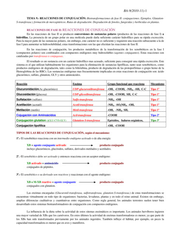
6 Chapter 1: OverviewChapter 1: OverviewThe Backup Interface is a key component in SolarEdge's Flexible Backup solution,controlling disconnection of house loads from the grid in the event of grid interruption.Homeowners are automatically provided with backup power in the event of gridinterruption to whole home or selected loads. Solar energy can be stored in a batteryfor Smart Energy Management applications such as export control, offering demandresponse and peak shaving, and performing time of use shifting for reduced electricbills.StorEdge Solution ComponentsEnergy Hub inverter - manages battery and system energy, in addition to itstraditional functionality as a DC-optimized PV inverter.The StorEdge Connection Unit, located at the bottom of the inverter, allows simpleinstallation and connectivity to other system components and includes a DC SafetySwitch.One or two batteries (optional) - DC-coupled batteries designed to work with theSolarEdge system. The batteries can be connected to the system optionally andrequire the Backup Interface to be installed.Backup Interface - controls disconnection of house loads from the grid andintegrates the following components to enable grid-tied solar backup and SmartEnergy Management. The Backup Interface must be installed to allow the operationof batteries.Energy Meter - is used by the inverter for export, import, production andconsumption readings, and for Smart Energy Management applications, suchas: export limitation, time-of-use profile programming and maximizing selfconsumption.Auto-transformer - handles the phase load balancing.200A microgrid interconnection device - disconnects the house loads from thegrid in case of a power outage.Generator hardware support - supports connection for up to 15kW alternativepower supply. Generator connection requires supporting inverter firmware.Backup Interface Installation Guide MAN-01-00729-1.1
Chapter 1: Overview7Figure 1: Energy Hub system componentsNOTEPV modules connected to power optimizers are not mandatory for charge/discharge profile programming.Installation Equipment ListStandard tools can be used during the installation of the SolarEdge system. Thefollowing is a recommendation of the equipment needed for installation:Allen screwdriver for 5mm screw type for the inverter enclosure screwsStandard flat-head screwdrivers setNon-contact voltage detectorCordless drill (with a torque clutch) or screwdriver and bits suitable for the surfaceon which the inverter and optimizers will be installed and for opening the StorEdgeConnection Unit drill guides. Use of an impact driver is not allowed.Mounting hardware (stainless bolts, nuts, and washers) for attaching:Backup Interface Installation Guide MAN-01-00729-1.1
8 Installation Equipment Listthe mounting brackets to the mounting surfacethe power optimizer to the rackingWire cutters (for wires of up to 4/0 AWG)Wire strippers (for wires of up to 4/0 AWG)VoltmeterFor installing the communication options, you may also need the following:For Ethernet:CAT6 twisted pair Ethernet cable with RJ45 connectorIf using a CAT6 cable spool: RJ45 plug and RJ45 crimperFor RS485:Four- or six-wire shielded twisted pair cableWatchmaker precision screwdriver setBackup Interface Installation Guide MAN-01-00729-1.1
Chapter 2: Installing and Connecting the Backup InterfaceChapter 2: Installing and Connecting theBackup InterfaceThis section explains how to install the Backup Interface and connect it to the inverter,AC loads panel and grid.Package ContentsBackup InterfaceMounting bracketConduit holderAccessories bag that contains:Bonding jumper for connecting the neutral and grounding barTwo mounting bracket screwsOne conduit holder screwAllen key (affixed to the bottom of the Backup Interface)Installation guideMounting the Backup InterfaceBefore you beginThe conduit entries are closed with drill guides. Drill the conduit entries open beforemounting the Backup Interface.CAUTION!HEAVY OBJECT. To avoid muscle strain or back injury, use proper liftingtechniques, and if required - a lifting aid.ATTENTION!Objet lourd. Pour éviter la fatigue musculaire ou des blessures au dos, utilisezdes techniques de levage appropriées et, si nécessaire - un auxiliaire de levagelors du retrait.NOTEMake sure the mounting surface or structure can support the weight of theBackup Interface and bracket, and make sure that it spans the width of thebracket.NOTEIf installing the Backup Interface in the line-side of the main service panel,maintain a distance of not more than 25 ft from the main service panel.Backup Interface Installation Guide MAN-01-00729-1.19
10 Installing the Conduit HolderTo mount the Backup Interface:1. Determine the Backup Interface mounting location, on a wall, stud framing or pole.It is recommended to mount the Backup Interface in a location protected fromdirect sunlight.2. To allow proper heat dissipation, maintain at least a 4" clearance between theBackup Interface and other objects.3. Position the mounting bracket against the wall/pole and mark the drilling holelocations.4. Drill the holes and mount the bracket. Verify that the bracket is firmly attached tothe mounting surface.5. Hang the Backup Interface on the bracket.Figure 2: Mounting the Backup Interface6. Insert the two supplied screws through the outer heat sink fin on both sides of theBackup Interface and into the bracket. Tighten the screws with a torque of 35 in*lbs/ 4.0 N*m.Installing the Conduit HolderTo ensure the Grid and AC Loads conduits are firmly secured in their place, a conduitholder is supplied with the Backup Interface.Install the conduit holder only after mounting the Backup Interface.Backup Interface Installation Guide MAN-01-00729-1.1
Chapter 2: Installing and Connecting the Backup InterfaceTo install the conduit holder:1. Insert the conduit holder in the space between the fins of the heat sink and themounting surface.2. Slide the conduit holder first to the left and then down to hang it on the short finand the bolt affixed to the outer left fin.Figure 3: Installing the Backup Interface3. Mark spots for drilling on the mounting surface.Figure 4: Marking drilling spots4. Remove the conduit holder.Backup Interface Installation Guide MAN-01-00729-1.111
12 Installing the Conduit Holder5. Drill two holes where marked.Figure 5: Drilling holes6. Install the conduit holder.7. Tighten the conduit holder to the mounting surface with two screws.Figure 6: Securing the conduit holder with screws8. Tighten the conduit holder to the outer left fin with the supplied screw. Tighten thescrew with a torque of 41.6 in*lbs / 4 N*m.Backup Interface Installation Guide MAN-01-00729-1.1
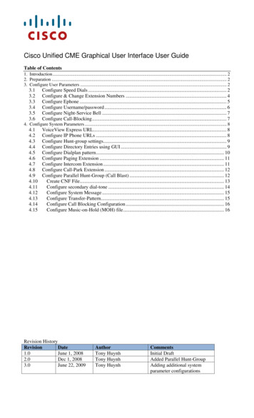
Chapter 2: Installing and Connecting the Backup InterfaceBackup Interface InterfacesThe following figure shows the Backup Interface interfaces for operating andconnecting to other system components.Install cable conduits, as required by local regulations.Figure 7: Backup Interface InterfacesInverter AC inputs - AC cables from up to three inverters.Generator AC input - an AC cable from one external generator.Grid AC input - an AC cable from the grid.Loads AC output - an AC cable to the loads panel.Communication input - Communication cables from inverters and external rapidshutdown switch.ON/OFF switch - When ON, enables automatic transition to backup mode. WhenOFF, enables manual control of the Backup Interface.LEDs - Three LEDs (AC, Comm, Fault) indicate system performance. For moreinformation, see System Performance LED Indication on page 25.Main circuit breaker control switch - Toggles the main circuit breaker. Pulling thelever down switches off the main circuit breaker.Backup Interface Installation Guide MAN-01-00729-1.113
14 Connecting the Backup Interface to the Grid and AC Loads PanelConnecting the Backup Interface to the Grid and ACLoads PanelFor connecting the Backup Interface to the grid and loads panel, use the followingcable types:For the grid - 4-4/0 AWGFor the loads panel - 4-4/0 AWGNOTEBacking up high-consumption loads, such as whole home air conditioners andwell pumps, requires installation of a soft start device (not supplied bySolarEdge) on the AC supply of these loads.To connect to the Grid and Loads panels1. Release the six Allen screws of the Backup Interface cover and remove the cover.NOTEDo not remove the internal plastic cover (dead front).2. Install a conduit of the required diameter into the Loads conduit entry. Use theconduit holder to support the conduit.3. Install a conduit of the required diameter into the Grid conduit entry. Use theconduit holder to support the conduit.4. Remove the plastic covers from Loads terminals.5. If required, connect the grounding and neutral bars with the bonding jumper,supplied with the Backup Interface. Tighten the bonding screws with a torque of41.6 in*lbs / 4 N*m.6. Pass the cable from the AC Loads panel through the Loads conduit.7. Pass the cable from the grid through the Grid conduit.8. Connect the neutral and grounding wires to the neutral and grounding terminals.Tighten the terminal screws with a torque of 200 in*lbs / 22.5 N*m.Backup Interface Installation Guide MAN-01-00729-1.1
Chapter 2: Installing and Connecting the Backup Interface159. Connect Line 1 and Line 2 wires from the AC loads panel to the loads line terminal.Tighten the terminal screws with a torque of 200 in*lbs / 22.5 N*m.Figure 8: Connection to the AC Loads Panel10. Connect the Line 1 and Line 2 wires to the grid's line terminal. Tighten the terminalscrews with a torque of 200 in*lbs / 22.5 N*m.Figure 9: Connection to the Grid11. Reinstall the plastic covers onto the loads terminals.Backup Interface Installation Guide MAN-01-00729-1.1
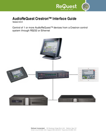
16 Connecting the Backup Interface to the InverterConnecting the Backup Interface to the InverterWhen connecting the Backup Interface to the Single phase energy hub inverter withprism technology, use the following cable types:Communication - 5-wire shielded twisted pair cable, 24 AWG (16-24 AWG), 600Vinsulated or CAT612V power - 16 AWG cableAC power - 6 AWG (4-20 AWG), 600V insulated cableNOTEIf an auto-transformer is connected to the inverter, make sure to disconnect itbefore connecting the Backup Interface.To connect to the communication cable and 12V cable1. Install a conduit of the required diameter into the Com 1 conduit entry.2. Connect the cabels to the Connection Unit of the inverter:a. Open Communication 1 gland.b. Pass the cables through the gland.c. Remove the 7-pin connector from the slot labeled Backup Interface on thecommunication board.d. Connect the cable wires to the 7-pin connector, as shown below, and reconnectthe connector to the slot:Figure 10: Communication and 12V cables connection between Backup Interface andInverterBackup Interface Installation Guide MAN-01-00729-1.1
Chapter 2: Installing and Connecting the Backup Interface173. Connect the cables to the Backup Interface:a. Pass the cables through the Com 1 conduit.b. Remove the 7-pin connector from the Backup Interface's communication slot.c. Connect the communication cable to the 7-pin connector, as shown above. Ifthere is a short circuit jumper between the RSD terminals of the inverter, removeit before connecting the RSD terminals to the Backup Interface.d. Reconnect the 7-pin connector to the communication slot.e. Move up (ON) the communication DIP switch.Figure 11: Communication DIP switch setupTo connect to the AC cable1. Connect one end of the AC cable to the AC terminal block in the inverter'sConnection Unit, as explained in the Single phase energy hub inverter with prismtechnology Installation Guide.2. Install a conduit of the required diameter into the Backup Interface's Inv1 conduitentry.Backup Interface Installation Guide MAN-01-00729-1.1
18 Connecting the Backup Interface to an External Rapid Shutdown Switch3. Pass the other end of the AC cable through the Inv1 conduit.Figure 12: AC connection between the Backup Interface and Inverter4. Connect the L1 and L2 wires of the AC cable to the Inv1 terminal block, as shownabove. Apply a torque of 17.7 in*lbs / 2 N*m.5. Connect the Neutral wire to the Neutral bar.6. Connect the Grounding wire to the Grounding bar.Connecting the Backup Interface to an External RapidShutdown SwitchIn accordance with regulation requirements, an external shutdown switch must beinstalled. The switch (not supplied by SolarEdge) shuts down the Backup Interface incase of emergency.Backup Interface Installation Guide MAN-01-00729-1.1
Chapter 2: Installing and Connecting the Backup InterfaceTo connect to an External Rapid Shutdown Switch1. Pass the cable form the switch through the Com 2 conduit.Figure 13: External rapid shutdown switch connection2. Remove the 2-pin connector labeled EXT RSD.3. Remove the short circuit jumper from the 2-pin connector.4. Connect the cable to the 2-pin connector, as shown above.5. Insert the 2-pin connector back into the EXT RSD port.6. Reinstall the Backup Interface cover and tighten it with the screws. Apply a torqueof 36.6 in*lbs / 3 N*m.Backup Interface Installation Guide MAN-01-00729-1.119
20 Chapter 3: System ConfigurationChapter 3: System ConfigurationThis chapter explains how to configure your Backup Interface using the SetApp mobileapplication.Before you begin, make sure the inverter firmware version is 4.8xx or higher. Forinformation on updating your inverter firmware, refer to the Inverter Installation Guide.To enable Backup Configuration:Open SetApp and select Commissioning Power Control Energy Manager Backup Configuration Backup Enable.After the Backup Configuration is enabled, the Backup Interface is automaticallyconfigured.Backup Interface Installation Guide MAN-01-00729-1.1
Troubleshooting21TroubleshootingErrorCodeError Message26x4Backup Interface stateinconsistent26x5Backup Interface stateinconsistent26x6Backup Interface stateinconsistent26x726xF26x1126x1226x143xBDBackup Interfacethresholds errorInverter doesn't lower ACvoltageBackup Interface lowtemperatureBackup Interface hightemperaturePhase imbalance toohighBackup Interface commerrorTroubleshootingManually switch the Backup Interface to on-grid(see Manually S
Installation Equipment List Standard tools can be used during the installation of the SolarEdge system. The following is a recommendation of the equipment needed for installation: Allen screwdriver for 5mm scr