Transcription
Significant changes fromthe 2011 to the 2014 editionof ACI 318Satyendra K. GhoshThe American Concrete Institute (ACI) has published Building Code Requirements for Structural Concrete (ACI 318-14) and Commentary(ACI 318R‑14),1 and it has been adopted by the 2015International Building Code (IBC).2 Thus, whenever the2015 IBC is adopted by a local jurisdiction, as it will be bythe state of California on January 1, 2017, ACI 318-14 willbe law within that jurisdiction. The 2014 edition of American Concrete Institute (ACI)’s BuildingCode Requirements for Structural Concrete (ACI 318-14) andCommentary (ACI 318R-14) has undergone a complete reorganization from its 2011 edition. ACI 318-14 contains a number of significant technical changes, with some of the most important in chapter 18, “EarthquakeResistant Structures.” Changes from ACI 318-11 to ACI 318-14 are discussed in thispaper.56Mar c h – Ap r il 2 0 1 6 PCI JournalAs is fairly well known by now, ACI 318 has undergone acomplete reorganization from its 2011 to its 2014 edition. In view of the effort involved in the reorganization,the initial expectation was that the number of technicalchanges in ACI 318-14 would be minimal. However, it didnot end up that way. ACI 318-14 does contain a number ofsignificant technical changes, some of the most importantof which are found in chapter 18, “Earthquake ResistantStructures.” Organizational changes from ACI 318-113 toACI 318-14 are discussed, followed by a chapter-by-chapter list of the significant technical changes. Throughoutthe paper, underlining is used to indicate text that was notin ACI 318-11 but has been added in ACI 318-14; striking out has been used to indicate text that was included inACI 318-11 but has been deleted from ACI 318-14.
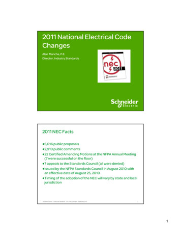
Organizational changesOverall changesOrganization of ACI 318-11There are some overall changes in the makeup ofACI 318‑14 that should be noted. There are two new chapters: chapter 4, “Structural System Requirements,” andchapter 12, “Diaphragms.”The organization of ACI 318-11 followed a framework thatwas started with ACI 318-71.4 There have been eight editions in between, in 1977, 1983, 1989, 1995, 1999, 2002,2005, and 2008, with the framework remaining essentiallyunchanged.ACI 318-11, following initial chapters on materials andconstruction aspects, dealt with analysis and design andstrength and serviceability requirements in two succeedingchapters. Next, there were three behavior-based chapters,one on flexure and axial loads, one on shear and torsion,and one on development and splices of reinforcement.The document then switched to member-based chapters:two-way slab systems, walls, and footings. Finally, therewere chapters on precast concrete, composite concreteflexural members, prestressed concrete, shells and foldedplate members, strength evaluation of existing structures,earthquake-resistant structures, and structural plain concrete. There were also four appendixes, including one onstrut-and-tie models and one on anchoring to concrete.Member-based organizationin ACI 318-14While the ACI 318 cycle that produced ACI 318-055 andACI 318-086 was still in full swing, it was decided afterlong deliberation within ACI, in the course of which external input was actively sought and considered, that ACI 318should be reorganized as a member-based document. Theidea was that within each chapter devoted to a particularmember type, such as beam or column, the user would findall the requirements necessary to design that particularmember type. Cary Kopczynski,7 an ACI 318 committeemember, says, “This will eliminate the need to flip throughseveral chapters to comply with all of the necessary designrequirements for a particular structural member, as wasnecessary with the old organization format. The code’s newdesign can be compared to a cookbook: all the ingredientsfor baking a cake such as eggs, flour, sugar, oil—alongwith the baking instructions—are in one chapter, instead ofindividual chapters on eggs, flour, and sugar.”Toolbox chaptersOne challenge in converting to a member-based organization was determining where to place design informationthat applies to multiple member types, such as development-length requirements. To repeat essentially the sameinformation in multiple chapters did not make sense because that would make the ACI 318 standard much longerand more unwieldy, so the decision was made to housesuch information in “toolbox” chapters and to reference theinformation from the member-based chapters.Appendix B of ACI 318-11, “Alternative Provisions forReinforced and Prestressed Concrete Flexural and Compression Members, “and appendix C, “Alternative Loadand Strength Reduction Factors,” have been discontinued.Appendix A, “Strut-and-Tie Models,” is now chapter 23,and appendix D, “Anchoring to Concrete,” is chapter 17 inthe reorganized document. No changes of any significancehave been made in the provisions of chapter 23 or appendix D.Three other chapters have remained intact: chapter 20,now 27, “Strength Evaluation of Existing Structures;”chapter 21, now 18, “Earthquake-Resistant Structures;”and chapter 22, now 14, “Structural Plain Concrete.” Thereare significant technical changes in chapter 18 and none inchapter 27 or 14. Chapter 1, “General” (previously “General Requirements”); chapter 2, “Notation and Terminology” (previously “Notation and Definitions”), and chapter3, “Referenced Standards” (previously “Materials”) are inthe same category in the sense that they have remained essentially the same entities but with changes in content.Chapter 16, “Precast Concrete,” and chapter 18, “Prestressed Concrete,” no longer exist as separate entities. Theprovisions of those chapters are now spread over several ofthe new chapters.Chapter 19, “Shells and Folded Plates,” is no longer partof the reorganized document. ACI Committee 318, in collaboration with ACI-ASCE Committee 334, Concrete ShellDesign and Construction, has developed ACI 318.2-14,8whose contents match those of ACI 318-11 chapter 19.(The reader may wonder why this document was designated ACI 318.2 rather than ACI 318.1. This is because itwas initially planned that ACI 318-11 chapter 22 on plainconcrete would become a separate standard, ACI 318.1.The number was reserved for that purpose. It was laterdecided to place the contents of ACI 318-11 chapter 22 inACI 318-14 chapter 14.)Table 1 shows a side-by-side comparison of the organization of ACI 318-11 and ACI 318-14.ACI 318-14 has no appendixes. It is likely that appendixeswill be acquired in time because ACI 318 appendixes haveserved a useful purpose in the past by providing a homefor material on its way into the standard (ACI 318-11 appendixes A and D, for example) or material on its way out(ACI 318-11 appendixes B and C, for example).PCI Journal M a r c h – A p r i l 201657
Table 1. Reorganization of ACI 318-14 compared with ACI 318-11ACI 318-11Descriptionof provisionsChapter and titleACI 318-14Descriptionof provisions1 - General r2 - Notation and DefinitionsMember-basedIntroductory4 - Durability Requirements4 - Structural System RequirementsOther6 - Structural Analysis7 - Details of Reinforcement7 - One-Way Slabs8 - Analysis and Design—General Considerations8 - Two-Way Slabs9 - Strength and Serviceability Requirements9 - BeamsMember-based11 - Walls12 - Development and Splices of Reinforcement12 - Diaphragms13 - Two-Way Slab Systems13 - Foundation16 - Precast ConcreteOther18 - Prestressed ConcreteConnectionsOther19 - Shells and Folded Plate Members20 - Strength Evaluation of ExistingStructures14 - Plain ConcreteMaterials17 - Anchoring to ConcreteIntact18 - Earthquake-Resistant StructuresIntact19 - Code Requirements for Thin Shellsand CommentaryACI 318.220 - Steel Reinforcement Properties, Durability, and Embedments21 - Strength Reduction Factors22 - Structural Plain Concrete22 - Sectional StrengthApp. A - Strut-and-Tie Models23 - Strut-and-Tie ModelsMar c h – Ap r il 2 0 1 6 PCI JournalIntactToolbox24 - Serviceability RequirementsApp. C - Alternative Load and StrengthReduction Factors (discontinued)App. D - Anchoring to ConcreteIntact16 - Connections between Members21 - Earthquake-Resistant StructuresApp. B - Alternative Provisions for Reinforced and Prestressed Concrete Flexuraland Compression Members (discontinued)New15 - Beam-Column and Slab-ColumnJoints17 - Composite Concrete Flexural Members5810 - Columns11 - Shear and Torsion14 - WallsNew5 - Loads6 - Formwork, Embedded Pipes, and Construction Joints15 - FootingsOther2 - Notation and Terminology3 - Referenced Standards5 - Concrete Quality, Mixing, and PlacingComment1 - General3 - Materials10 - Flexure and Axial LoadsBehavior-basedChapter and title25 - Reinforcement DetailsConstruction26 - Construction Documents and InspectionOther27 - Strength Evaluation of ExistingStructuresIntact
Construction documentsand inspectionA unique chapter that the user will probably require sometime to get used to is chapter 26, “Construction Documentsand Inspection.” The chapter starts with the following:seismic hooks at both ends. A closed tie shall not bemade up of interlocking headed deformed bars.A definition for special seismic systems, a term used inchapters 18 and 19, has been added:special seismic systems — Structural systems that usespecial moment frames, special structural walls, or both.26.1.1 This chapter addresses (a) through (c):(a) Design information that the licensed design professional shall specify in the construction documents,(b) Compliance requirements that the licensed designprofessional shall specify in the construction documents,(c) Inspection requirements that the licensed designprofessional shall specify in the construction documents.Thus, construction and inspection requirements have beenconsolidated, and they are now related to constructiondocuments. The construction requirements are designatedeither as “design information” or “compliance requirements.” These are largely existing materials that have beenrearranged. The primary intent of these provisions is thatthe licensed design professional must now provide all ofthe construction requirements in the project drawings andspecifications, rather than referring to ACI 318.Chapter 3: Referenced StandardsThe following referenced specifications have been addedto section 3.2.4: ASTM A370-14, Standard Test Methods and Definitions for Mechanical Testing of Steel Products9 ASTM A1085-13, Standard Specification for ColdFormed Welded Carbon Steel Hollow Structural Sections (HSS)10 ASTM C173/C173M-14, Standard Test Method forAir Content of Freshly Mixed Concrete by the Volumetric Method 11 ASTM C1582/C1582M-11, Standard Specification forAdmixtures to Inhibit Chloride-Induced Corrosion ofReinforcing Steel in Concrete12The following referenced specifications have been deleted:The inspection requirements in section 26.13 are takenfrom chapter 17 of the 2015 IBC2 and were previously notpart of ACI 318. ASTM C109/C109M-08, Standard Test Method forCompressive Strength of Hydraulic Cement Mortars(Using 2-in. or [50-mm] Cube Specimens)13 ASTM C192/C192M-07, Standard Practice forMaking and Curing Concrete Test Specimens in theLaboratory14Technical changesChapter 1: GeneralGeneral information regarding the scope and applicabilityof ACI 318 is provided.A new section on interpretation is included to help usersbetter understand the ACI 318 provisions.Chapter 2: Notationand TerminologyEngineers are specifying use of interlocking headed deformed bars to form the legs of hoops. The use of interlocking headed bars is a concern because of the possibilitythat heads will not be adequately interlocked and becausethe heads could become disengaged under complex loadings well into the nonlinear range of response. Therefore,the definition for hoops has been modified as follows:hoop — Closed tie or continuously wound tie, made upof one or several reinforcement elements, each havingSeveral referenced standards and specifications have beenupdated, as always happens with every new edition ofACI 318. Note that the edition of every referenced standardis important. ACI 318 does not necessarily adopt new editions of referenced standards unless they are vetted beforethe publication of each edition of the standard.Chapter 4: Structural SystemRequirementsThis chapter has been added to ACI 318-14 to introducestructural system requirements. This chapter containssections on materials, design loads, structural system andload paths, structural analysis, strength, serviceability,durability, sustainability, structural integrity, fire resistance,requirements for specific types of construction, construction and inspection, and strength evaluation of existingstructures. Most of these sections refer to other chaptersPCI Journal M a r c h – A p r i l 201659
in ACI 318-14. The section on construction and inspection, for instance, refers to chapter 26. In the areas ofsustainability and fire resistance, ACI 318-14 does nothave specific requirements. The section on sustainabilityallows the licensed design professional to specify, in theconstruction documents, sustainability requirements inaddition to the strength, serviceability, and durabilityrequirements of ACI 318-14. The strength, serviceability,and durability requirements are required to take precedence over sustainability considerations, though theserequirements are generally in harmony with sustainablestructures. In the section on fire resistance, ACI 318 refersto the fire-protection requirements of the general buildingcode, saying only that where “the general building coderequires a thickness of concrete cover for fire protectiongreater than the concrete cover specified in 20.6.1, suchgreater thickness shall govern.” This would be the caseanyway because 2015 IBC2 section 102.4.1 explicitlystates, “Where conflicts occur between provisions of thiscode and referenced codes and standards, the provisionsof this code shall apply.”Chapter 5: LoadsThe following modification has been made in the provisionfor live load reduction because there are still unincorporated areas where there may not be a general building code:5.2.3 — Live load reductions shall be permitted inaccordance with the general building code or, in theabsence of a general building code, in accordance withASCE/SEI 7.For many code cycles, ACI 318 retained provisions forservice-level earthquake forces in design load combinations. In 1993, ASCE 715 converted earthquake forces tostrength-level forces and reduced the earthquake load factor to 1.0, and the model building codes followed suit. Inmodern building codes around the world, earthquake loadsare now strength-level forces. Therefore, any referencesto service-level earthquake forces including the followingACI 318-11 section have been deleted:9.2.1 (c) Where E, the load effects of earthquake, isbased on service-level seismic forces, 1.4E shall be usedin place of 1.0E in Eq. (9-5) and (9-7).A requirement to include secondary moments was properlyincluded in the ACI 318-11 section on moment redistribution but was not included anywhere else. Becausesecondary moments are significant considerations when amember is being designed, including when moments arenot redistributed, they should be included in the memberchapters. Also, the effects of reactions induced by prestressing include more than just secondary moments, sothe language is modified to reflect this. Two new sectionsshould be noted:60Mar c h – Ap r il 2 0 1 6 PCI Journal5.3.11 — Required strength U shall include internalload effects due to reactions induced by prestressingwith a load factor of 1.0.7.4.1.3 — For prestressed slabs, effects of reactions induced by prestressing shall be considered in accordancewith 5.3.11.Sections 8.4.1.3 and 9.4.1.3 have, similarly, been added tothe chapters on two-way slabs and beams, respectively.Chapter 6: Structural AnalysisThe following new item has been added in section 6.6.2.3:(b) For frames or continuous construction, it shall be permitted to assume the intersecting member regions are rigid.ACI 318 has so far been silent on the use of finite element analysis (FEA), though it is now frequently used.Chapter 6 has added section 6.9 with provisions that areintended to explicitly allow the use of FEA and to providea framework for the future expansion of FEA provisions.It is not the purpose of the added provisions to serve as aguide toward the selection and use of FEA software. Thenew chapter on diaphragms and collectors makes an explicit reference to the use of FEA, which makes it imperative that ACI 318 recognize the acceptability of its use.Chapter 8: Two-Way SlabsACI 318-11 section 18.9.1 required a minimum area ofbonded reinforcement to be provided in all flexural members with unbonded tendons. The purpose of the minimum bonded reinforcement over the tops of columns isto distribute cracking caused by high local flexural tensilestresses in areas of peak negative moments. However, thehigh local tensile stresses are not unique to slabs withunbonded tendons. ACI 318-14 section 8.6.2.3 requires thesame minimum bonded reinforcement in slabs with unbonded or bonded tendons, except that the area of bondedtendons is considered effective in controlling cracking.ACI Committee 318 also decided that if the same bonded reinforcement were required for both bonded and unbonded posttensioned two‐way systems, the structural integrity requirements for both systems should also be the same. The structuralintegrity requirements in ACI 318-11 section 18.12.6 appliedto two-way posttensioned slab systems with unbonded tendonsonly. The structural integrity requirements in ACI 318-14 section 8.7.5.6 now apply to two-way posttensioned slab systemswith bonded as well as unbonded tendons.Chapter 9: BeamsThe use of open web reinforcement for torsion and shear inslender spandrel beams has been suggested by the precast
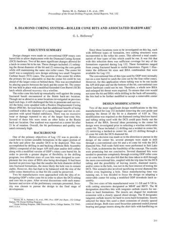
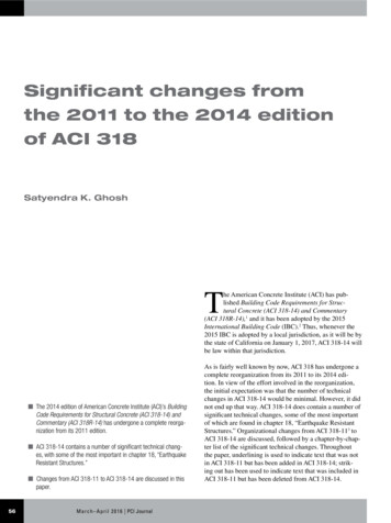
reduces reinforcement congestion, especially in the endregions of slender spandrels, while maintaining a desiredlevel of safety.The relevant newly added ACI 318-14 section readsFigure 1. Precast concrete spandrel specimen tested at North Carolina StateUniversity. Image from Lucier et al., “Development of a Rational Design Methodology for Precast Concrete Slender Spandrel Beams: Part 1, ExperimentalResults” (2011).concrete industry as an alternative to the closed stirrupstraditionally mandated by ACI 318. Eliminating closed stirrups is desirable because they cause reinforcement congestion; production costs also increase significantly becausepretensioning strand must be threaded through the closedstirrups.An extensive PCI-sponsored experimental and analyticalresearch program was conducted at North Carolina StateUniversity (NCSU).16,17 The objective was to develop arational design procedure for slender precast concretespandrel beams. Specifically, the research was aimed atsimplifying the detailing requirements for the end regionsof such beams. The end regions are often congested withheavy reinforcement cages when designed using currentprocedures.Sixteen precast concrete spandrel beams were testedto failure (Fig. 1). All specimens were full-scale, mostspanning 45 ft (13.7 m). Two of the test specimens weredesigned and detailed with closed stirrups, according tocurrent practice, to serve as controls for the experimentalprogram. The remaining specimens were designed withvarious configurations of open web reinforcement. Several specimens were specially configured to force failuresin their end regions by adding extra ledge, flexural, andhanger reinforcement.9.5.4.7— For solid precast sections with an aspectratio h/bt 4.5 [bt width of that part of cross sectioncontaining the closed stirrups resisting torsion, in.], itshall be permitted to use an alternative design procedureand open web reinforcement, provided the adequacy ofthe procedure and reinforcement have been shown byanalysis and substantial agreement with results of comprehensive tests. The minimum reinforcement requirements of 9.6.4 and detailing requirements of 9.7.5 and9.7.6.3 need not be satisfied.The research at NCSU is referenced in commentary section C9.5.4.7.Chapter 12: DiaphragmsACI 318 has, for many editions, contained design anddetailing requirements, found in ACI 318-11 section 21.11or ACI 318-14 section 18.12, for diaphragms in structuresassigned to seismic design category (SDC) D, E, or F,as defined in ASCE 7-10.18 ACI 318-14 has, for the firsttime, added design provisions in the new chapter 12 fordiaphragms in buildings assigned to SDC C and lower. Thenew chapter applies “to the design of nonprestressed andprestressed diaphragms, including (a) through (d):(a) Diaphragms that are cast-in-place slabs(b) Diaphragms that comprise a cast-in-place toppingslab on precast elementsIn addition to the experimental program, finite elementmodels were developed (Fig. 2) and calibrated to experimental data. These models were used in conjunction withconventional analysis to corroborate the experimentalresults and to further investigate the behavior of slenderprecast concrete spandrel beams.The results of this research demonstrated that properlydesigned open web reinforcement is a safe, effective, andefficient alternative to traditional closed stirrups for slenderprecast concrete spandrels. A simple, rational design procedure was developed. This proposed procedure significantlyFigure 2. Finite element model of a precast concrete spandrel beam. Imagefrom Lucier et al., “Development of a Rational Design Methodology for PrecastConcrete Slender Spandrel Beams: Part 2, Analysis and Design Guidelines”(2011).PCI Journal M a r c h – A p r i l 201661
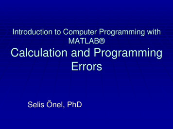
column confinement. ACI 318, through its 2011 edition,did not explicitly account for confinement effectiveness indetermining the required amount of confinement. It insteadassumed constant confinement effectiveness independentof how the reinforcement is distributed.In view of this, confinement requirements for columns ofspecial moment frames (section 18.7.5) Fig. 4) with highaxial load (Pu 0.3Ag f c', where Pu is the factored axialforce, Ag is the gross area of concrete section;,and f c' is thespecified compressive strength of concrete) or high concrete compressive strength ( f c' 10,000 psi [6895 MPa])are significantly different in ACI 318-14.Figure 3. Precast concrete double-tee deck diaphragm. Image courtesy of PatHynes, Knife River Prestress Division, Harrisburg, Ore.(c) Diaphragms that comprise precast elements withend strips formed by either a cast-in-place concretetopping slab or edge beams(d) Diaphragms of interconnected precast elementswithout cast-in-place concrete topping.” (Fig. 3)Chapter 12 follows the format of the other member-basedchapters.Chapter 18: Earthquake-ResistantStructuresThere are a number of significant and substantive changesin this chapter.One important new requirement for special moment framecolumns is as follows:18.7.5.2 — Transverse reinforcement shall be in accordance with (a) through (f):(f) Where Pu 0.3Ag f c' or f c' 10,000 psi in columns with rectilinear hoops, every longitudinalbar or bundle of bars around the perimeter of thecolumn core shall have lateral support provided bythe corner of a hoop or by a seismic hook, and thevalue of hx shall not exceed 8 in. (Fig. 5). Pu shallbe the largest value in compression consistent withfactored load combinations including E.where hx maximum center-to-center spacing of longitudinalbars laterally supported by corners of crossties orhoop legs around the perimeter of the columnColumn confinement The ability of the concretecore of a reinforced concrete column to sustain compressive strains tends to increase with confinement pressure.Compressive strains caused by lateral deformation areadditive to the strains caused by axial load. It follows thatconfinement reinforcement should be increased with axialload to ensure consistent lateral deformation capacity.The dependence of the amount of required confinementon the magnitude of axial load imposed on a column hasbeen recognized by some codes from other countries (suchas CSA A23.3-1419 and NZS 3101-0620,21) but was notreflected in ACI 318 through its 2011 edition.The ability of confining steel to maintain core concreteintegrity and increase deformation capacity is also relatedto the layout of the transverse and longitudinal reinforcement. Longitudinal reinforcement that is well distributedand laterally supported around the perimeter of a columncore provides more-effective confinement than a cagewith larger, widely spaced longitudinal bars. Confinement effectiveness is a key parameter determining thebehavior of confined concrete (Mander et al.22) and hasbeen incorporated into the CSA A23.3-1419 equation for62Mar c h – Ap r il 2 0 1 6 PCI JournalFigure 4. Confinement of rectangular column of special moment frame. Note:h1 plan dimension of column in one of two orthogonal directions; h2 plandimension of column in other orthogonal direction; ℓo length, measured fromjoint face along axis of member, over which special transverse reinforcementmust be provided; s center-to-center spacing of items, such as longitudinalreinforcement, transverse reinforcement, tendons, or anchors. 1 in. 25.4 mm.
Table 2. Confinement of high-strength or highly axially loaded rectangular column of special moment frame in ACI 318-14Transverse reinforcementConditionsApplicable expressions AgPu 0.3 A g f c 'andGreater of (a) and (b) f' 1 c A ch f yt (a)0 .3 'cf 10,000 psiA shsb c0 .09for rectilinear hoopPu 0.3 A g f c 'andGreater of (a), (b) and (c)0 .2 k f k n'f c 10,000 psif c'(b)f ytPuf yt A ch(c)Source: Data from ACI 318-14 Table 18.7.5.4.Note: Ach cross-sectional area of a member measured to the outside edges of transverse reinforcement; Ag gross area of concrete section; for ahollow section, Ag is the area of the concrete only and does not include the area of the void(s); Asb area of longitudinal reinforcement in shear wallboundary element; bc cross-sectional dimension of member core measured to the outside edges of the transverse reinforcement composing areaAsh; f c' specified compressive strength of concrete; fyt specified yield strength of transverse reinforcement; kf concrete strength factor; kn confinement effectiveness factor; Pu factored axial force, to be taken as positive for compression and negative for tension; s center-to-center spacingof items, such as longitudinal reinforcement, transverse reinforcement, tendons, or anchors.The change from prior practice is that instead of everyother longitudinal bar having to be supported by a cornerof a tie or a crosstie, every longitudinal bar will have to besupported when either the axial load on a column is high orthe compressive strength of the column concrete is high.The other new requirement for special moment frame columns is in the following section:18.7.5.4 — Amount of transverse reinforcement shall bein accordance with Table 18.7.5.4 (reproduced here asTable 2).The concrete strength factor kf and confinement effectiveness factor kn are calculated by (a) and (b).Figure 5. Confinement of high-strength or highly axially loaded rectangularcolumn of special moment frame. Note: db nominal diameter of bar, wire, orprestressing strand; hx maximum value of xi on all column faces greater than8 in.; xi dimension from centerline to centerline of laterally supported longitudinal bars. 1 in. 25.4 mm.kf f c' 0.6 1.025, 000nkn lnl 2(18.7.5.4a)(18.7.5.4b)where nl is the number of longitudinal bars or barbundles around the perimeter of a column core with rectilinear hoops that are laterally supported by the cornerof hoops or by seismic hooks.Special moment frame beam-column joints Forbeam-column joints of special moment frames, clarification of the development length of beam longitudinalreinforcement that is hooked, requirements for joints withheaded longitudinal reinforcement, and restrictions onjoint aspect ratio are new.ACI 318 joint design provisions are based on the assumption that joint shear strength is provided mainly by adiagonal compression strut that develops across the joint.Joint transverse reinforcement confines the concrete strut,enabling it to resist shear under force reversals. The strut ismost effective if the joint aspect ratio hbeam/hcolumn is close to1.0, where hbeam is the overall depth of the beam and hcolumnis the overall depth of the column. For very large aspectratios (Fig. 6), joint strength is likely to be reduced if asingle strut is used. For such joints, additional transversereinforcement might be required to support development ofconcrete struts that form at a shallower angle. It might alsobe necessary to modify the nominal joint shear strengthPCI Journal M a r c h – A p r i l 201663
Figure 6. Joint with high aspect ratio. Note: hbeam overall depth of beam;hcolumn overall depth of column.provisions in consideration of the steep strut (Fig. 6).Unfortunately, no tests on special moment frame jointswith high aspect ratios have been reported in the literature. In view of this, ACI 318-14 section 18.8.2.4 restrictshbeam/hcolumn to a value of 2 or less.The case of knee joints with headed beam reinforcement(Fig. 7) requires special consideration. In such joints, jointfailure can occur by a diagonal crack that extends beyondthe headed bars or by top-face blowout above the beambars. ACI 318-14 section 18.8.3.4, therefore, requires thatin such joints, “the column shall extend above the top ofthe joint a distance at least the depth h of the joint. Alternatively, the beam reinforcement shall be enclosed byadditional vertical joint reinforcement providing equivalentconfinement to the top face of the joint.”ASCE-ACI 352 recommends23 that where standard hooksare used, the hook should be bent into the joint, not awayFigure 7. Knee joint with headed beam reinforcement.64Mar c h – Ap r il 2 0 1 6 PCI Journal
The 2014 edition of American Concrete Institute (ACI)’s Building Code Requirements for Structural Concrete (ACI 318-14) and Commentary (ACI 318R-14) has undergone a complete reorga-nization from its 2011 edition. ACI 318-14 contains a number of significant technical chang-es, w