Transcription
Livingston , E., Scavuzzo, R. J. “Pressure Vessels”The Engineering Handbook.Ed. Richard C. DorfBoca Raton: CRC Press LLC, 2000 1998 by CRC PRESS LLC
9Pressure Vessels9.1Design CriteriaDesign Loads Materials Allowable Stress9.29.3Design FormulasOpening ReinforcementEarl LivingstonBabcock and Wilcox Company, RetiredRudolph J. ScavuzzoUniversity of AkronPressure vessels used in industry are leak-tight pressure containers, usually cylindrical orspherical in shape, with different head configurations. They are usually made from carbon orstainless steel and assembled by welding. Early operation of pressure vessels and boilersresulted in numerous explosions, causing loss of life and considerable property damage.Some 80 years ago, the American Society of Mechanical Engineers formed a committee forthe purpose of establishing minimum safety rules of construction for boilers. In 1925 thecommittee issued a set of rules for the design and construction of unfired pressure vessels.Most states have laws mandating that these Code rules be met. Enforcement of these rulesis accomplished via a third party employed by the state or the insurance company. TheseCodes are living documents in that they are constantly being revised and updated bycommittees composed of individuals knowledgeable on the subject. Keeping currentrequires that the revised Codes be published every three years with addendas issued everyyear. This chapter covers a very generalized approach to pressure vessel design based on theASME Boiler and Pressure Vessel Code, Section VIII, Division 1: Pressure Vessels.9.1 Design CriteriaThe Code design criteria consist of basic rules specifying the design method, design load,allowable stress, acceptable material, and fabrication inspection certification requirementsfor vessel construction.The design method known as "design by rule" uses design pressure, 1998 by CRC PRESS LLC
allowable stress, and a design formula compatible with the geometry of the part to calculatethe minimum required thickness of the part. This procedure minimizes the amount ofanalysis required to ensure that the vessel will not rupture or undergo excessive distortion. Inconjunction with specifying the vessel thickness, the Code contains many constructiondetails that must be followed. Where vessels are subjected to complex loadings such ascyclic, thermal, or localized loads, and where significant discontinuities exist, the Coderequires a more rigorous analysis to be performed. This method is known as the "design byanalysis" method. A more complete background of both methods can be found in Bernstein,1988.The ASME Code [1994] is included as a standard by the American National StandardsInstitute ( ANSI). The American Petroleum Institute (API) has also developed codes forlow-pressure storage tanks, and these are also part of the ANSI standards. The ASME Boilerand Pressure Vessel Code has been used worldwide, but many other industrialized countrieshave also developed boiler and pressure vessel codes. Differences in these codes sometimescause difficulty in international trade.Design LoadsThe forces that influence pressure vessel design are internal/external pressure; dead loadsdue to the weight of the vessel and contents; external loads from piping and attachments,wind, and earthquakes; operating-type loads such as vibration and sloshing of the contents;and startup and shutdown loads. The Code considers design pressure, design temperature,and, to some extent, the influence of other loads that impact the circumferential (or hoop)and longitudinal stresses in shells. It is left to the designer to account for the effect of theremaining loads on the vessel. Various national and local building codes must be consultedfor handling wind and earthquake loadings.MaterialsThe materials to be used in pressure vessels must be selected from Code-approved materialspecifications. This requirement is normally not a problem since a large catalogue of tableslisting acceptable materials is available. Factors that need to be considered in picking asuitable table are:CostFabricabilityService condition (wear, corrosion, operating temperature)AvailabilityStrength requirementsSeveral typical pressure vessel materials for a noncorrosive environment and for servicetemperatures between ¡50 F and 1000 F are shown in Table 9.1. 1998 by CRC PRESS LLC
Table 9.1 Acceptable Pressure Vessel MaterialsTemperature Use Limit ( F)Down to -50 33 to 775 776 to 1000Plate Material SA-516All gradesSA-285Gr. CSA-515Gr. 55, 60, 65SA-516All gradesSA-204Gr. B, CSA-387Gr. 11, 12Class 1Pipe MaterialForging MaterialSA 333Gr. 1SA-53SA-106SA 350Gr. LF1, LF2SA-181Gr. I, IISA-335Gr. P1, P11,P12SA-182Gr. F1, F11,F12 Impact testing required.Note:SA is a classification of steel used in the ASME Boiler and Pressure Vessel Code.Allowable StressThe allowable stress used to determine the minimum vessel wall thickness is based on thematerial tensile and yield properties at room and design temperature. When the vesseloperates at an elevated temperature, the creep properties of the material must also beconsidered. These properties are adjusted by design factors which limit the hoop membranestress level to a value that precludes rupture, and excessive elastic or plastic distortion andcreep rupture. Table 9.2 shows typical allowable stresses for several carbon steels commonlyused for unfired pressure vessels.Table 9.2 Typical Allowable Stresses for Use in Pressure Vessel DesignMaterial SpecificationSA-515 Gr. 60SA-516 Gr. 70 1998 by CRC PRESS LLCTemperature Use Limit ( F)700800900700800Allowable Stress (psi)14 40010 8006 50016 60014 500
SA-53 Gr. ASA-106 Gr. BSA-181 Gr. I90070080090070080090070080090012 00011 7009 3006 50014 40010 8006 50016 60012 0006 5009.2 Design FormulasThe design formulas used in the "design by rule" method are based on the principal stresstheory and calculate the average hoop stress. The principal stress theory of failure states thatfailure occurs when one of the three principal stresses reaches the yield strength of thematerial. Assuming that the radial stress is negligible, the other two principal stresses can bedetermined by simple formulas based on engineering mechanics.The Code recognizes that the shell thickness may be such that the radial stress may not benegligible, and adjustments have been made in the appropriate formulas. Table 9.3 showsvarious formulas used to calculate the wall thickness for numerous pressure vesselgeometries.Table 9.3 Code Formulas for Calculation of Vessel Component ThicknessCylindrical shellt Hemispherical head or spherical shellt 2:1 ellipsoidal headt Flanged and dished headt Flat headwheret P R S D L E C PRSE¡0:6PPR2SE¡0:2PPD2SE¡0:2P1:77P L2SE¡0:2Ppt d CP SEMinimum required thickness (in.)Design pressure (psi)Inside radius (in.)Allowable stress (psi)Inside diameter (in.)Inside spherical crown radius (in.)Weld joint efficiency factor, determined by joint location and degree of examinationFactor depending upon method of head-to-shell attachment 1998 by CRC PRESS LLC
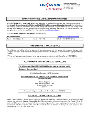
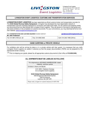
9.3 Opening ReinforcementVessel components are weakened when material is removed to provide openings for nozzlesor access. High stress concentrations exist at the opening edge and decrease radiallyoutward from the opening, becoming negligible beyond twice the diameter from the centerof the opening. To avoid failure in the opening area, compensation or reinforcement isrequired. Some ways in which this can be accomplished are: (a) increase the vessel wallthickness, (b) increase the wall thickness of the nozzle, or (c) use a combination of extrashell and nozzle thickness. The Code procedure is to relocate the removed material to anarea within an effective boundary around the opening. Figure 9.1 shows the steps necessaryto reinforce an opening in a pressure vessel. Numerous assumptions have been made withthe intent of simplifying the general approach.Figure 9.1 Opening Reinforcement Requirements.The example shown in Fig. 9.2 uses the design approach indicated by the Code to perform asimple sizing calculation for a typical welded carbon steel vessel. Figure 9.3 shows a typicalshell-nozzle juncture and head-shell juncture which meet the code requirements. Designspecifications for the many associated vessel parts such as bolted flanges, externalattachments, and saddle supports can be found in the reference materials. 1998 by CRC PRESS LLC
Figure 9.2 Sample vessel calculation. 1998 by CRC PRESS LLC
Figure 9.3 Fabrication details. 1998 by CRC PRESS LLC
Defining TermsCode: The complete rules for construction of pressure vessels as identified in ASME Boilerand Pressure Vessel Code, Section VIII, Division 1, Pressure Vessels.Construction: The complete manufacturing process, including design, fabrication,inspection, examination, hydrotest, and certification. Applies to new construction only.Hoop membrane stress: The average stress in a ring subjected to radial forces uniformlydistributed along its circumference.Longitudinal stress: The average stress acting on a cross section of the vessel.Pressure vessel: A leak-tight pressure container, usually cylindrical or spherical in shape,with pressure usually varying from 15 psi to 5000 psi.Stress concentration: Local high stress in the vicinity of a material discontinuity such as achange in thickness or an opening in a shell.Weld efficiency factor: A factor which reduces the allowable stress. The factor depends onthe degree of weld examination performed during construction of the vessel.ReferencesAmerican Society of Mechanical Engineers. 1994. ASME Boiler and Pressure Vessel Code,Section VIII Division 1, Pressure Vessels. ASME, New York.Bednar, H. H. 1981. Pressure Vessel Design Handbook. Van Nostrand Reinhold, New York.Bernstein, M. D. 1988. Design criteria for boiler and pressure vessels in the U.S.A. ASME J. P 443.Jawad, M. H. and Farr, J. R. 1989. Structural Analysis and Design of Process Equipment,2nd ed. John Wiley & Sons, New York.Further InformationEach summer, usually in June, the Pressure Vessels and Piping Division of the AmericanSociety of Mechanical Engineers organizes an annual meeting devoted to pressure vesseltechnology. Usually 300 to 500 papers are presented, many of which are published byASME in booklets called special publications. Archival papers are also published in theJournal of Pressure Vessel Technology.Research for ASME Boiler and Pressure Code work is often conducted by the PressureVessel Research Council (PVRC). This research is normally published in Welding ResearchCouncil bulletins . These bulletins, which number about 400, are an excellent documentationof major research contributions in the field of pressure vessel technology. The ElectricPower Research Institute (EPRI) located in Palo Alto, California, also conducts extensiveresearch for the electric power industry, and this work includes some research on pressure 1998 by CRC PRESS LLC
Pressure vessel: A leak-tight pressure container, usually cylindrical or spherical in shape, with pressure usually varying from 15 psi to 5000 psi. Stress concentration: Local high stress in the vicinity of a material discontinuity such as a