Transcription
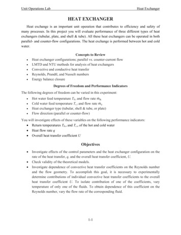
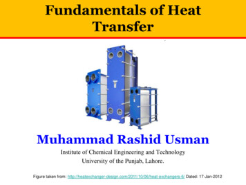
HEAT TRANSFERHEAT EXCHANGERTypes of Heat ExchangersHeat exchangers are classified according to flow arrangement and type ofconstruction.1. Double-pipe heat exchanger – one fluid flows through the smallerpipe while the other fluid flows through the annular space betweenthe two pipes.(a) Parallel flow – the hot and cold fluids enter the same end,flow in the same direction and leave at the same end.Figure 1(a): Double-pipe heat exchanger – parallel flow(b) Counter flow – the hot and cold fluids enter at opposite ends,flow in opposite direction and leave at opposite ends.Figure 1(b): Double-pipe heat exchanger – counter flowHEAT TRANSFER1HEAT EXCHANGERS
2. Crossflow heat exchanger – the flow of one fluid is perpendicularto the other fluid.(a) Unmixed – fluid is said to be unmixed because the finsprevent motion in the y direction.Figure 2(a): Cross-flow heat exchanger – finned both fluidunmixedxy(b) MixedFigure 2(b): Cross-flow heat exchanger – unfinned with onefluid mixed the other fluid unmixedxyHEAT TRANSFER2HEAT EXCHANGERS
3. Shell-and-tube heat exchanger – baffles are included to increase theconvection coefficient of the shell-side fluid by inducingturbulenceFigure 3(a): Shell-and-tube heat exchanger with one shelland one tube passFigure 3(b): Multi-pass flow arrangement – one-shell passand two tube-passesFigure 3(c): Multi-pass flow arrangement – one-shell passand two tube-passesHEAT TRANSFER3HEAT EXCHANGERS
4. Compact heat exchanger – these device have dense arrays of finnedtubes or plates and are typically used when at least one of the fluidsis a gas.HEAT TRANSFER4HEAT EXCHANGERS
The Overall Heat Transfer CoefficientA heat exchanger typically involves two flowing fluids separated by asolid wall. Heat is first transferred from the hot fluid to the wall byconvection, through the wall by conduction, and from the wall to the coldfluid again by convection. Any radiation effects are usually included inthe convection heat transfer coefficients. The thermal resistance networkassociated with this heat transfer process is given below.R Rtotal Ri Rwall Ro ln(ro / ri )11 hi Aiho Ao2 kLi inner & o outerR 1UAln(ro / ri )11111 2 kLUAs U i Ai U o Ao hi Aiho AoHEAT TRANSFER5HEAT EXCHANGERS
When the wall thickness of the tube is small and the thermal conductivityof the tube material is high, as is usually the case, the thermal resistanceof the tube is negligible (Rwall 0) and the inner and outer surfaces of thetube are almost identical (Ai Ao As).1 1 1 U hi hoFouling FactorThe performance of heat exchangers usually deteriorates with time as aresult of accumulation of deposits on heat transfer surfaces. The layer ofdeposits represents additional resistance to heat transfer and causes therate of heat transfer in a heat exchanger to decrease. The net effect ofthese accumulations on heat transfer is represented by a fouling factor Rf,which is a measure of the thermal resistance introduced by fouling. Theunits of Rf is (K/W).When considering fouling factor is considered, the overall heat transfercoefficient has to be modified as given below.R f ,i ln(ro / ri ) R f ,o11111 2 kLUAs U i Ai U o Ao hi AiAiAoho AoQuestion 1:A double-pipe heat exchanger is constructed of a stainless steel (k 15.1W/m · K) inner tube of inner diameter Di 1.5 cm and outer diameter Do 1.9 cm and an outer shell of inner diameter 3.2 cm. The convection heattransfer coefficient is given to be hi 800 W/m2 · K on the inner surfaceof the tube and ho 1200 W/m2 · K on the outer surface. For a foulingfactor of Rf, i 0.0004 m2 · K/ W on the tube side and Rf, o 0.0001m2 · K/ W on the shell side, determine,(a) the thermal resistance of the heat exchanger per unit length and(b) the overall heat transfer coefficients, Ui and Uo based on theinner and outer surface areas of the tube, respectively.HEAT TRANSFER6HEAT EXCHANGERS
HEAT TRANSFER7HEAT EXCHANGERS
04.05.2009 · Heat exchangers are classified according to flow arrangement and type of construction. 1. Double-pipe heat exchanger – one fluid flows through the smaller pipe while the other fluid flows through the annular space between the two pipes. (a)Parallel flow – the hot and cold fluids enter the same end, flow in the same direction and leave at the same end. Figure 1(a): Double-pipe heat .