Transcription
Introduction to Loudspeakersand EnclosuresD. G. MeyerSchool of Electrical & ComputerEngineering
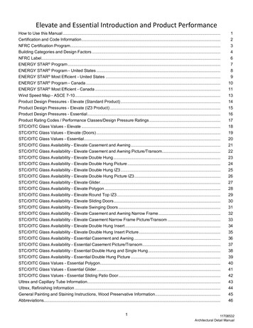
Outline Background– How loudspeakers work– Waveforms– Wavelengths– Speed of sound– How sound propagates– Sound pressure level (dB)– Summation of audio signals– Phase wheel– Beamwidth– 3D directivity “balloons”
How Loudspeakers Work
How Loudspeakers Are Made
The Waveform
Transmissionλ C/FC is speedof sound atambientconditions
Transmission
How Sound Propagates
Acoustic Decibel (dB SPL) In acoustics, the ratios most commonlyencountered are changes in pressure level,measured in dB-SPL:dB-SPL 20 log10(p/po) where po 20 µN/m2 As distance from a sound source doubles,the dB-SPL decreases 6 dB (this is calledthe inverse square law) Adding/subtracting dB levels:SPLa SPLb 10 log10 [ 10 db-SPLa/10 10db-SPLb/10] Doubling acoustic power corresponds to a3 dB increase in SPL Doubling perceived loudness corresponds toa 10 dB increase in SPL
Transmission
Transmission
Transmission
Transmission
Electrical Power Requirement When SPL goal at a given listening distanceknown, also need:– Sensitivity rating of loudspeaker (typically specas 1m on-axis with input of 1 electrical watt)– Acoustic level change/attenuation betweenloudspeaker and farthest listening position Example: 90 dB program level at listeningdistance of 32 m outdoors– Loudspeaker sensitivity measured as 110 dB– Acoustic level change 20 log (32) 30 dB– Add 10 dB for peak (program level) headroom– SPL required at source is 90 30 10 130 dB– Need 20 dB above 1 watt, or 10 (20/10) 100 W
Stable Summation Criteria1. Must have matched origin2. May contain unlimited multiple inputs3. May arrive from different directions4. Must have significant overlap duration
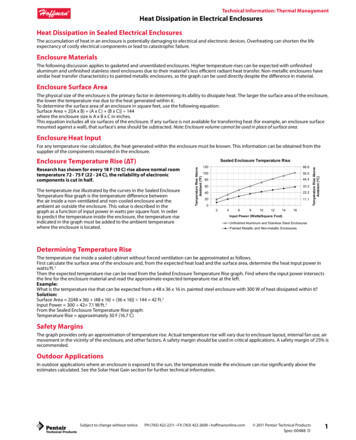
Summation Criteria: Matched OriginSummed SignalSignal 1Signal 2Σ SummationSummed SignalSignal 1Signal 2Σ Summation
Summation Criteria: Matched OriginSummed SignalSignal 1Signal 2Σ SummationSummed SignalSignal 1Signal 2Σ Summation?
Summation Criteria: Multiple Input SignalsSummed SignalSignal 1Signal 2Signal 3Signal 4Signal nΣ Summation
Summation Criteria: Input Signal Direction
Summation Criteria: Overlap DurationSummed SignalS1Σ SummationS2Addition/subtractionduring overlapdurationSummed SignalS1Σ SummationS2No addition/subtraction
Adding dB-SPLTwo acoustic sources “a” and “b” of relative phase angles θa and θbΣdB-SPLa b 20 log10 [sqrt { (10dB-SPLa/20)2 (10dB-SPLb/20)2 2(10dB-SPLa/20) (10dB-SPLb/20)(cos(θa-θb))} ]
Adding dB-SPL – “Simplifications”If both sources are in phase and only the relative level varies (wheresource “a” is 0 dB, simplifies to:ΣdB-SPLa b 20 log10 [1 10dB-SPLb/20 ]If both sources are at 0 dB and phase angle θa 0 (i.e., same level,only relative phase angle varies), simplifies to :ΣdB-SPLa b 20 log10 [ sqrt { 2 2cos(-θb) } ]
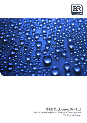
Acoustic Addition & Subtraction: The Phase Wheeltwo identical signals summed at same level
Acoustic Addition & Subtraction: Level vs. Phasetwo identical signals summed at same level
Factors Affecting Response atSummation Point1.Level offset due to distance offset(inverse square law)2.Level offset due to polar response(frequency dependent)3.Phase offset due to path lengthdifference
Summation: Response Ripple1.Time offsets shift all frequencies by thesame amount of time2.Time offsets shift all frequencies by adifferent amount of phase3.Result of summation with time offset(of signals at same frequency) is responseripple
Summation Zones Defined Coupling zone– Sources within 1/3 wavelength ( 120º)– Amount of addition ranges for 0 to 6 dBdepending on phase/level offset– Ripple is 3 dB– Most easily achieved at low frequencies dueto large wavelengths
Summation Zones Defined Cancellation zone– Effects only subtractive– Phase offset 150º to 180º– Ripple 50 dB
Summation Zones Defined Combing Zone– Phase offset reaches point where subtractionbegins ( 120º)– Less than 4 dB level difference– Characterized by addition at somefrequencies and dips at others– Ripple ranges from 6 dB to 50 dB– To be avoided – highest form of variance overfrequency
Summation Zones Defined Combining Zone– Level offset ranges from 4 dB to 10 dB– Semi-isolated state relative to sources, whichlimits the magnitude of addition/cancellation– Ripple no more than 6 dB
Summation Zones Defined Isolation Zone– 10 dB or more of level offset– Relative interactions steadily reduced andeventually become negligible– At large level offset, relative phase hasnominal effect– Ripple does not exceed 6 dB
Summation
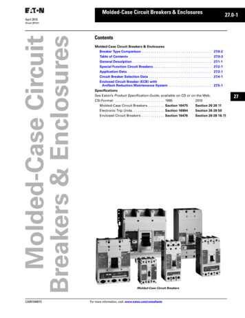
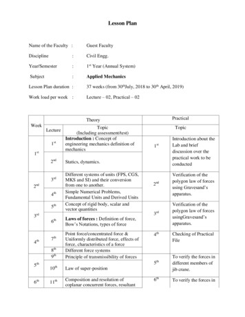
Acoustic Addition and Subtraction: Level Offset EffectsLevel Offset EffectsMax Ripple24.0Relative Phase 0 deg18.0Relative Phase 180 degL e v e l C h a n g e (d B Level OffsetMax Peak HeightMax Null DepthMax Ripple151617181920
Summation
Application loudspeaker mounted in a rigid (undamped) pipe3 feet in length, open at one end, observed onaxis from “speaker end”3 feet
Application how does sound propagate at low frequencies?3 feet
Application how does sound propagate at low frequencies?3 feet
Application if operated at 150 Hz, how much phase shiftoccurs as the wave traverses the pipe?3 feet
Application if operated at 150 Hz, how much phase shiftoccurs as the wave traverses the pipe?wavelength 7.53 feet; phase shift (360x3)/7.53 143 degrees3 feet
Application what will be level of “combined” signal atobservation point?3 feet
Application what will be level of “combined” signal atobservation point? total “round trip” phase shift 180 143 143 466 degrees (106 degrees net);combined level will be 1.7 dB3 feet
Application if frequency changed to 100 Hz, what will becombined level? wavelength is 11.3 feet; phaseshift traversing pipe 96 degrees; round trip phaseshift is 371 degrees (nearly “in phase”); combinedlevel is 5.95 dB3 feet
Coverage / Beamwidth
Common Representations of Loudspeaker Coverage Coverage angle C (H / V) 6 dB BeamwidthPolar patternEqual level (isobaric) contours (“isobars”)Directivity factor (Q)Directivity index (DI) 10 log Q (also known as“front to back ratio”) Beamwidth vs. frequency 3D “balloons”
Transmission
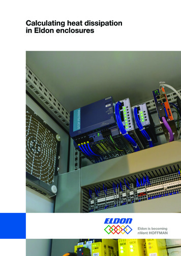
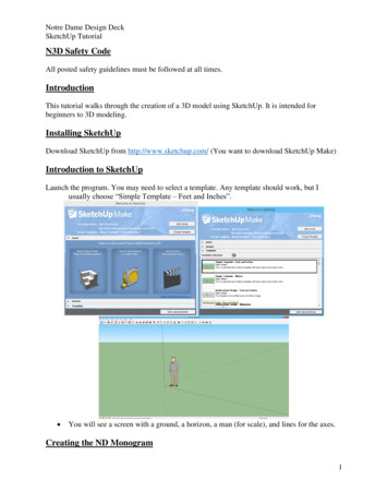
Example: Piston radiation into half-space (e.g., a cone-typeloudspeaker mounted in an “infinite” bafflethink of piston asconsisting of a largenumber of very smallelements of size S
In general, want ka 3.83 for a cone radiator,where k 2πf/cExamples: For 12” woofer, want f 1378 HzFor 4” midrange, want f 4134 Hz3.83central lobe onlypair of out-of-phaseside lobesadditional pair ofin-phase side lobes
Single 4-inch Loudspeaker
Single 4-inch Loudspeaker @ 500 Hz
Single 4-inch Loudspeaker @ 1000 Hz
Single 4-inch Loudspeaker @ 2000 Hz
Single 4-inch Loudspeaker @ 4000 Hz
32-Element Array of 4-inch Drivers
32-Element Array @ 500 Hz
32-Element Array @ 1000 Hz
32-Element Array @ 2000 Hz
32-Element Array @ 4000 Hz
“Home Stereo” Multi-way System
“Home Stereo” Multi-way System
“Home Stereo” Multi-way System
“Home Stereo” Multi-way System
“Home Stereo” Multi-way System
“Home Stereo” Multi-way System
“Home Stereo” Multi-way System
Outline Overview of enclosure types– Infinite baffle– Sealed box– Bass reflex (vented/ported)– Passive radiator– Horn (front and rear loaded)– Transmission line (labyrinth)– Tapered tube (damped pipe/“waveguide”)
Infinite Baffle
Sealed Box
Bass Reflex
Measurement of Loudspeaker Free-Air Resonance
Passive RadiatorComment: primarily applicable to subwoofer design
Compound / Band-passComment: primarily applicable to subwoofer design
Front-loaded HornComment: primarily applicable to mid/high frequencies
Rear-loaded HornComment: physically large!
Transmission Line / LabyrinthLength of transmission linehas to be long enough toprovide at least 90º ofphase shift (1/4 of longestwavelength of interest)Phase shift (degrees) 360 x L / (C/F)where L is effective lengthof labyrinth, C is speed ofsound, and F is frequencyof operation (note – add180 due to rear radiation)
Transmission Line / Labyrinth Transmission line – typically “heavilydamped” (stuffed with acoustic material) toabsorb energy from rear vibrating surface(or limit radiation from vent to lowfrequencies) Labyrinth – typically “lined” (with acousticabsorption material) but otherwise“substantially open” (radiation from ventlimited to low frequencies)
Damped Pipe Pipe driven at one end and open at theother will resonate at a frequency ofFres C / 4L, where C is the speed ofsound (1130 ft/sec at 72º F) and L is theeffective length of the pipe (Fres is called its“quarter-wavelength tuning” frequency) The effective (or “acoustic”) length of thepipe may be longer than its physical length Use of tapering and/or acoustic absorptionmaterial can increase the effective length
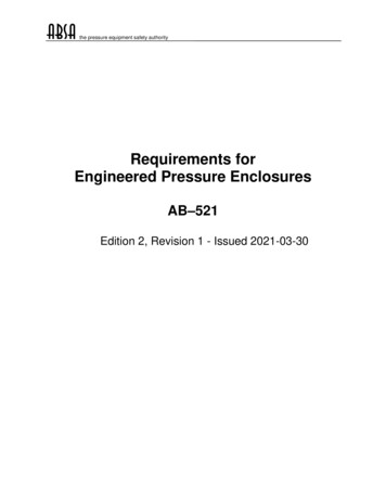
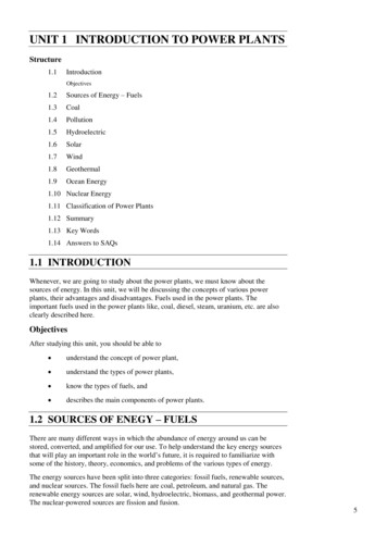
Damped Pipe / Tapered TubeIllustration from: G. L. Augspurger, “Loudspeakers on Damped Pipes,”J. Audio Eng. Soc., vol. 48, pp. 424-436 (2000 May).
Bose AWR1 “Waveguide”Illustration from: Fig. 4 of U.S. Patent 6,278,789
Bose WRII “Waveguide”Illustration from: Fig. 6B of U.S. Patent 7,565,948
Bose WRII “Waveguide”Illustration from: Fig. 9 of U.S. Patent 7,584,820
Summary Viable enclosure types for project– sealed box– bass reflex / tuned port– transmission line / labyrinth– coupling chamber (tapered) damped pipe Materials supplied– half sheet (4’x4’) of 3/4” MDF (cut per your specs)– acoustic lining/stuffing material– PVC pipe and couplers (per your specs)– glue (carpenter’s yellow, PVC cleaner/cement)
References Loudspeaker Design Cookbook, Vance Dickason (any edition) U.S. Patent 3,523,589 “High Compliance Speaker and EnclosureCombination” U.S. Patent 4,655,315 “Speaker System” U.S. Patent 5,821,471 “Acoustic System” U.S. Patent 6,278,789 “Frequency Selective Acoustic WaveguideDamping” U.S. Patent 7,426,280 “Electroacoustic Waveguide Transducing” U.S. Patent 7,565,948 “Acoustic Waveguiding” M. J. King, “Construction and Measurement of a Simple TestTransmission Line,” accessed from http://www.quarter-wave.com G. L. Augspurger, “Loudspeakers on Damped Pipes,” J. Audio Eng. Soc.,vol. 48, pp. 424-436 (2000 May). L. J. S. Bradbury, “The Use of Fibrous Materials in LoudspeakerEnclosures,” J. Audio Eng. Soc., vol. 24, pp. 162-170 (1976 April).
Summation: Response Ripple 1.Time offsets shift all frequencies by the same amount of time 2.Time offsets shift all frequencies by a different amount of phase 3.Result of summation with time