Transcription
DGX A100 SystemUser GuideDU-09821-001 v06 May 2022
Table of ContentsChapter 1.Introduction. 11.1 Hardware Overview . 21.1.1 DGX A100 Models and Component Descriptions . 21.1.2 Mechanical Specifications . 31.1.3 Power Specifications. 41.1.3.1 Support for N N Redundancy . 41.1.3.2 DGX A100 Locking Power Cord Specification . 41.1.3.3 Using the Locking Power Cords . 51.1.3.3.1 Locking/Unlocking the PDU Side . 51.1.3.3.2 Locking/Unlocking the PSU Side (Cords with Switch-Lock Mechanism) . 51.1.3.3.3 Locking/Unlocking the PSU Side (Cords with Twist-Lock Mechanism) . 61.1.4 Environmental Specifications . 61.1.5 Front Panel Connections and Controls . 71.1.5.1 With a Bezel. 71.1.5.2 With the Bezel Removed . 81.1.6 Rear Panel Modules. 81.1.7 Motherboard Connections and Controls . 91.1.8 Motherboard Tray Components . 91.1.9 GPU Tray Components . 101.2 Network Connections, Cables, and Adaptors . 101.2.1 Network Ports . 101.2.2 Supported Network Cables and Adaptors . 121.3 DGX A100 System Topology . 121.4 DGX OS Software . 121.5 Additional Documentation . 131.6 Customer Support . 13Chapter 2.Connecting to the DGX A100 . 142.1 Connecting to the Console . 142.1.1 Direct Connection . 142.1.2 Remote Connection through the BMC . 162.2 SSH Connection to the OS . 18Chapter 3.First Boot Setup . 193.1 System Setup . 193.2 Post Setup Tasks . 213.2.1 Obtain Software Updates . 223.2.2 Enabling the srp daemon . 22DGX A100 SystemDU-09821-001 v06 ii
Chapter 4.Quick Start and Basic Operation . 234.1 Installation and Configuration . 234.2 Registration . 234.3 Obtaining an NGC Account . 244.4 Turning DGX A100 On and Off . 244.4.1 Startup Considerations . 244.4.2 Shutdown Considerations. 244.5 Verifying Functionality – Quick Health Check . 244.6 Running a Preflight Stress Test . 254.7 Running the NGC Containers with GPU Support . 264.7.1 Using Native GPU Support . 264.7.2 Using the NVIDIA Container Runtime for Docker . 274.8 Managing CPU Mitigations . 284.8.1 Determining the CPU Mitigation State of the DGX System. 284.8.2 Disabling CPU Mitigations . 294.8.3 Re-enabling CPU Mitigations . 29Chapter 5.Additional Features and Instructions . 305.1 Managing the DGX Crash Dump Feature. 305.1.1 Using the Script. 305.1.2 Connecting to Serial Over LAN to View the Console . 31Chapter 6.Managing the DGX A100 Self-Encrypting Drives . 326.1 Overview . 326.2 Installing the Software . 336.3 Configuring Trusted Computing . 336.3.1 How to Tell if Drives Support Block SID . 346.3.2 Enabling the TPM and Preventing the BIOS from Sending Block SID Requests . 346.4 Initializing the System for Drive Encryption. 356.5 Enabling Drive Locking . 366.6 Initialization Examples . 366.6.1 Example 1: Passing in the JSON File. 366.6.1.1 Determining Which Drives Can be Managed as Self Encrypting . 366.6.1.2 Creating the Drive/Password Mapping JSON Files and Using it to Initialize theSystem . 376.6.2 Example 2: Generating Random Passwords . 386.6.3 Example 3: Specifying Passwords One at a Time When Prompted . 386.7 Disabling Drive Locking . 386.8 Exporting the Vault . 396.9 Erasing your Data . 396.10 Clearing the TPM. 39DGX A100 SystemDU-09821-001 v06 iii
6.11 Changing Disk Passwords, Adding Disks, or Replacing Disks . 406.12 Recovering From Lost Keys. 40Chapter 7.Network Configuration . 417.1 Configuring Network Proxies . 417.1.1 For the OS and Most Applications . 417.1.2 For apt . 417.1.3 For Docker . 427.2 Configuring Docker IP Addresses . 427.3 Open Ports . 437.4 Connectivity Requirements for NGC Containers . 437.5 Configuring a Static IP Address for the BMC . 447.5.1 Configuring a BMC Static IP Address Using ipmitool . 447.5.2 Configuring a BMC Static IP Address Using the System BIOS. 457.6 Configuring a BMC Static IP Address for the Network Ports . 457.7 Switching Between InfiniBand and Ethernet . 467.7.1 Starting the Mellanox Software Tools and Determining the Current PortConfiguration . 477.7.2 Switching the Port Configuration . 47Chapter 8.8.18.28.3Configuring Storage . 49Setting Filesystem Quotas . 50Switching Between RAID 0 and RAID 5 . 50Configuring Support for Custom Drive Partitioning . 51Chapter 9.Updating and Restoring the Software . 529.1 Updating the DGX A100 Software . 529.1.1 Connectivity Requirements for Software Updates . 529.1.2 Update Instructions . 539.2 Restoring the DGX A100 Software Image . 539.2.1 Obtaining the DGX A100 Software ISO Image and Checksum File. 549.2.2 Remotely Reimaging the System . 549.2.3 Creating a Bootable Installation Medium . 559.2.3.1 Creating a Bootable USB Flash Drive by Using the dd Command . 569.2.3.2 Creating a Bootable USB Flash Drive by Using Akeo Rufus . 569.2.4 Re-Imaging the System from a USB Flash Drive . 589.2.5 Installation Options . 589.2.5.1 Retaining the RAID Partition While Installing the OS . 589.2.5.2 Advanced Installation Options (Encrypted Root - DGX OS 5 or later) . 599.2.5.3 Boot Into Live Environment (DGX OS 5 or later) . 609.2.5.4 Check Disc for Defects (DGX OS 5 or later) . 60Chapter 10. Using the BMC . 61DGX A100 SystemDU-09821-001 v06 iv
10.1.1 Connecting to the BMC . 6110.2 Overview of BMC Controls . 6210.3 Common BMC Tasks. 6310.3.1 Changing BMC Login Credentials . 6310.3.2 Using the Remote Console . 6410.3.3 Setting Up Active Directory or LDAP/E-Directory . 6510.3.4 Configuring Platform Event Filters . 6510.3.5 Uploading or Generating SSL Certificates. 6610.3.5.1 Viewing the SSL Certificate . 6610.3.5.2 Generating the SSL Certificate. 6710.3.5.3 Uploading the SSL Certificate . 6810.3.5.4 Updating the SBIOS Certificate . 68Chapter 11. SBIOS Settings . 7211.1 Accessing the SBIOS Setup . 7211.2 Configuring Boot Order . 73Chapter 12. Multi-Instance GPU . 74Chapter 13. Security . 7513.1 User Security Measures. 7513.1.1 Securing the BMC Port . 7513.2 System Security Measures . 7513.2.1 Secure Flash of DGX A100 Firmware . 7513.2.1.1 Encryption. 7513.2.1.2 Signing . 7613.2.1.3 NVSM Security . 7613.3 Secure Data Deletion . 7613.3.1 Prerequisite . 7613.3.2 Instructions . 76Chapter 14. Redfish APIs Support . 7814.1 Supported Features . 78Appendix A. Installing Software on Air-Gapped DGX 100 Systems . 80Appendix B. Safety . 90Appendix C. Compliance . 97DGX A100 SystemDU-09821-001 v06 v
Chapter 1. IntroductionThe NVIDIA DGX A100 system is the universal system purpose-built for all AI infrastructureand workloads, from analytics to training to inference. The system is built on eight NVIDIAA100 Tensor Core GPUs.This document is for users and administrators of the DGX A100 system.DGX A100 SystemDU-09821-001 v06 1
Introduction1.1Hardware Overview1.1.1DGX A100 Models and ComponentDescriptionsThere are two models of the NVIDIA DGX A100 system: the NVIDIA DGX A100 640GB systemand the NVIDIA DGX A100 320GB system.Table 1-1.Model DifferentiationComponentNVIDIA DGX A100 640GBNVIDIA DGX A100 320GBGPUQty 8 NVIDIA A100 GPUsQty 8 NVIDIA A100 GPUsThird-generation NVLinksThird-generation NVLinksTotal GPU Memory640 GB320 GBNVIDIA NVSwitchQty 6Qty 6Second generation (2x fasterthan first generation)Second generation (2x faster thanfirst generation)Qty 10 (Factory ship config)Qty 9 (Factory ship config)Mellanox ConnectX-6 VPIMellanox ConnectX-6 VPI HDR IB/200Gb/sNetworkingHDR InfiniBand/200 Gb/sEthernet(Optional Add-on: Second dual- port200 Gb/s Ethernet)CPU2 AMD Rome, 128 cores total2 AMD Rome, 128 cores totalSystem Memory2 TB (Factory ship config)1 TB (Factory ship config)(Optional Add-on: 1 TB to get 2 TBmax.)Storage30 TB (Factory ship config)15 TB (Factory ship config)U.2 NVMe DrivesU.2 NVMe Drives(Optional drive upgrade to 60 TB)(Optional Add-on: 15 TB to get 30 TBmax.Optional drive upgrade to 60 TB)DGX A100 SystemDU-09821-001 v06 2
IntroductionTable 1-2.Component DescriptionComponentDescriptionGPUNVIDIA A100 GPUCPU2x AMD EPYC 7742 CPU w/64 coresNVSwitch600 GB/s GPU-to-GPU bandwidthStorage (OS)1.92 TB NVMe M.2 SSD (ea) in RAID 1 arrayStorage (Data Cache)3.84 TB NVMe U.2 SED (ea) in RAID 0 array(Optional 7.68 TB NVMe U.2. SEDs)Network (Cluster) cardNetwork (Storage) card Mellanox ConnectX-6 Single Port VPI InfiniBand(default): HDR, HDR100, EDR Ethernet: 200GbE, 100GbE, 50GbE, 40GbE, 25GbE,and 10GbEMellanox ConnectX-6 Dual Port VPIEthernet (default): 200GbE, 100GbE, 50GbE, 40GbE,25GbE, and 10GbEInfiniBand: HDR, HDR100, EDRSystem Memory (DIMM)BMC (out-of-band systemmanagement)1 TB per 16 DIMMs1 GbE RJ45 interfaceSupports IPMI, SNMP, KVM, and Web UI, and the RedfishAPIsIn-band system management1 GbE RJ45 interfacePower Supply3 kW1.1.2Mechanical SpecificationsTable 1-3. Mechanical SpecificationsFeatureDescriptionForm Factor6U RackmountHeight10.4” (264 mm)Width19" (482.3 mm) maxDepth35.3" (897.1 mm) maxSystem Weight271.5 lbs (123.16 kg) maxDGX A100 SystemDU-09821-001 v06 3
Introduction1.1.3Power SpecificationsThe DGX A100 system contains six power supplies with balanced distribution of the powerload.Table 1-4.Power SpecificationsInputSpecification for Each Power Supply200-240 volts AC1.1.3.16.5 kW max.3000 W @ 200-240 V, 16 A, 50-60 HzSupport for N N RedundancyThe DGX A100 includes six power supply units (PSU) configured for 3 3 redundancy. If threePSUs fail, the system will continue to operate at full power with the remaining three PSUs.Note: If only two PSUs are working, the GPUs will not be available, but the server will still boot.This is to allow you to gather debug or system logs.If only one PSU is working, troubleshoot the cause for the loss of power from the other PSUs andcorrect. If faulty PSUs need to be replaced, shut the system down and install working PSUs.1.1.3.2DGX A100 Locking Power Cord SpecificationThe DGX A100 is shipped with a set of six (6) locking power cords that have been qualified foruse with the DGX A100 to ensure regulatory compliance. Two locking power cord types areapproved - switch-locking for the PSU side and twist-locking for the PSU side.WARNING: To avoid electric shock or fire, only use the NVIDIA-provided power cords to connectpower to the DGX A100. For more details, see Electrical Precautions in “Safety”.Table 1-5.Power Cord SpecificationsPower Cord FeatureSpecificationElectrical250VAC, 16APlug StandardC19/C20Dimension1200mm lengthComplianceCord: UL62, IEC60227Connector/Plug: IEC60320-1DGX A100 SystemDU-09821-001 v06 4
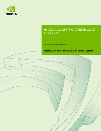
Introduction1.1.3.3Using the Locking Power CordsFollow these instructions for using the locking power cords.1.1.3.3.1Locking/Unlocking the PDU SidePower Distribution Unit side To INSERT, push the cable into the PDU socket. To REMOVE, press the clips together and pull the cord out of the socket.1.1.3.3.2Locking/Unlocking the PSU Side (Cords with Switch-LockMechanism)Power Supply (System) side - Switch locking To INSERT or REMOVE make sure the cable is UNLOCKED and push/ pull into/out of thesocketTo UNLOCK the power cord, movethe switch to the unlocked position(indicator will show GREEN)To LOCK the power cord, move theswitch to the locked position(indicator should show only RED)DGX A100 SystemDU-09821-001 v06 5
Introduction1.1.3.3.3Locking/Unlocking the PSU Side (Cords with Twist-LockMechanism)Power Supply (System) side - Twist locking To INSERT or REMOVE make sure the cable is UNLOCKED and push/ pull into/out of thesocketTo UNLOCK the power cord, twist thegray locking ring to the unlocked(indicator will show an unlockedpadlock)To LOCK the power cord, twist thegray locking ring to the lockedposition (indicator should show alocked padlock)1.1.4Environmental SpecificationsTable 1-6.Environmental SpecificationsFeatureSpecificationOperating Temperature5 C to 30 C (41 F to 86 F)Relative Humidity20% to 80% non-condensingAirflow840 CFM @ 80% fan PWMHeat Output22,179 BTU/hrDGX A100 SystemDU-09821-001 v06 6
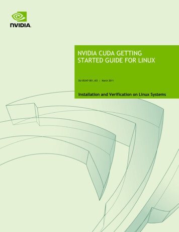
Introduction1.1.5Front Panel Connections and Controls1.1.5.1With a BezelTable 1-7.Front Panel ControlsControlDescriptionPower ButtonPress to turn the DGX A100 system On or OffID ButtonGreen flashing (1 Hz): Standby (BMC booted) Greenflashing (4 Hz): POST in progress Green solid On:Power OnPress to cause the button blue LED to turn Onor blink (configurable through the BMC) as anidentifier during servicing.Also causes an LED on the back of the unit to flash asan identifier during servicing.Fault LEDDGX A100 SystemAmber On: System or component faultedDU-09821-001 v06 7
Introduction1.1.5.2!With the Bezel RemovedImportant: See “Turning DGX A100 On and Off” for instructions on how to properly turn thesystem on or off.1.1.6DGX A100 SystemRear Panel ModulesDU-09821-001 v06 8
Introduction1.1.7Motherboard Connections and ControlsTable 1-8.Motherboard ControlsControlDescriptionPower ButtonPress to turn the system On or Off.ID LED ButtonBlinks when ID button is pressed from the front of the unitas an aid in identifying the unit needing servicingBMC Reset buttonPress to manually reset the BMCSee “Network Connections, Cables, and Adaptors” for details on the network connections.1.1.8DGX A100 SystemMotherboard Tray ComponentsDU-09821-001 v06 9
Introduction1.1.9GPU Tray Components1.2Network Connections, Cables, andAdaptors1.2.1Network PortsDGX A100 SystemDU-09821-001 v06 10
IntroductionTable 1-9.Network Port MappingPort DestinationsDefaultsRDMAOptionalOptionalSlotDGX OS 5and laterSlot 5 notpopulateSlot 5Populatedenp75s0mlx5 2mlx5 2ibp84s0enp84s0mlx5 3mlx5 3ibp186s0enp186s0mlx5 6mlx5 8ibp75s0enp204s0mlx5 7mlx5 9PCI BusPre-DGX aib2ca:00.0b baenp202s0b4 port 0 (top)e1:00.0enp225s0f0(See note)mlx5 8mlx5 104 port 1(bottom)e1:00.1enp225s0f1(See note)mlx5 9mlx5 115 port 0 (left)61:00.0enp97s0f0(See note)-mlx5 45 port 1(right)61:00.1enp97s0f1(See note)-mlx5 560c:00.0ib0enp12s0mlx5 0mlx5 0712:00.0ib1enp18s0mlx5 1mlx5 188d:00.1ib4enp141s0mlx5 6mlx5 6994:00.0ib5enp148s0mlx5 7mlx5 7LANe2:00.0enp226s0N/ANote: The interface enp37s0f3u1u3c2 or bmc redfish0 is recognized by the OS and may be listedin response to such commands as ifconfig or ip addr. This interface supports BMCcommunication using Redfish APIs.Note: The Optional column lists the port designations after reconfiguring the default InfiniBandports to Ethernet.When switching from the default Ethernet to InfiniBand, the InfiniBand port designations willvary depending on changes made to the other ports.abBased on systems updated with DGX A100 Firmware Update Container 20.10.9 or laterBased on systems updated with DGX A100 Firmware Update Container 20.05.12.3 or earlier.DGX A100 SystemDU-09821-001 v06 11
Introduction1.2.2Supported Network Cables and AdaptorsThe DGX A100 system is not shipped with network cables or adaptors. You will need topurchase supported cables or adaptors for your network.The ConnectX-6 firmware determines which cables and adaptors are supported. For a list ofcables and adaptors compatible with the Mellanox ConnectX-6 VPI cards installed in the DGXA100 system.1. Visit the Mellanox Firmware Release page.2. From the left navigation menu, select the ConnectX model and corresponding firmwareincluded in the DGX A100.3. Select Firmware Compatible Products.1.3DGX A100 System Topology1.4DGX OS SoftwareThe DGX A100 system comes pre-installed with a DGX software stack incorporating thefollowing: An Ubuntu server distribution with supporting packages The following system management and monitoring software NVIDIA System Management (NVSM) Provides active health monitoring and system alerts for NVIDIA DGX nodes in a datacenter. It also provides simple commands for checking the health of theDGX A100 SystemDU-09821-001 v06 12
Introduction DGX A100 system from the command line. Data Center GPU Management (DCGM) DGX A100 system support packages The NVIDIA GPU driver Docker Engine NVIDIA Container Toolkit Mellanox OpenFabrics Enterprise Distribution for Linux (MOFED) Mellanox Software Tools (MST) cachefilesd (daemon for managing cache data storage)1.5Additional Documentation MIG User GuideThe new Multi-Instance GPU (MIG) feature allows the NVIDIA A100 GPU to be securelypartitioned into up to seven separate GPU Instances for CUDA applications. NGC Container Registry for DGXHow to access the NGC container registry for using containerized deep learning GPUaccelerated applications on your DGX A100 system. NVSM Software User GuideContains instructions for using the NVIDIA System Management software. DCGM Software User GuideContains instructions for using the Data Center GPU Manager software.1.6Customer SupportContact NVIDIA Enterprise Support for assistance in reporting, troubleshooting, or diagnosingproblems with your DGX A100 system. Also contact NVIDIA Enterprise Support for assistance inmoving the DGX A100 system. For contracted Enterprise Support questions, you can send an email toenterprisesupport@nvidia.com. For additional details about how to obtain support, go to NVIDIA Enterprise Support.Our support team can help collect appropriate information about your issue and involveinternal resources as needed.DGX A100 SystemDU-09821-001 v06 13
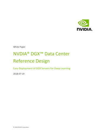
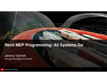
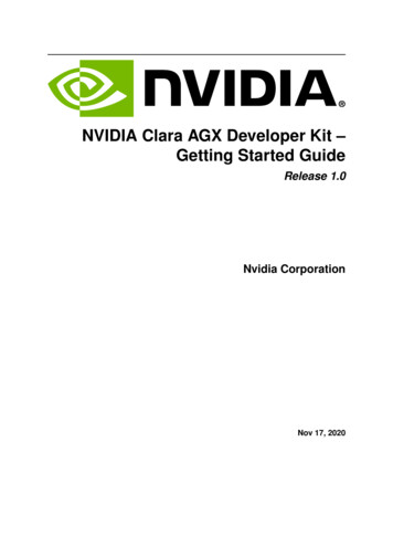
Chapter 2. Connecting to the DGX A1002.1Connecting to the ConsoleConnect to the DGX A100 console using either a direct connection or a remote connectionthrough the BMC.!CAUTION: Connect directly to the DGX A100 console if the DGX A100 system is connected to a172.17.xx.xx subnet.DGX OS Server software installs Docker Engine which uses the 172.17.xx.xx sub-net by default forDocker containers. If the DGX A100 system is on the same subnet, you will not be able toestablish a network connection to the DGX A100 system.Refer to “Configuring Docker IP Addresses” for instructions about how to change the defaultDocker network settings.2.1.1Direct ConnectionAt either the front or the back of the DGX A100 system, connect a display to the VGA connector,and a keyboard to any of the USB ports.Note: The display resolution must be 1440x900 or lower.DGX A100 SystemDU-09821-001 v06 14
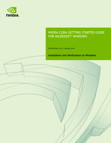
Connecting to the DGX A100Figure 2-1. DGX A100 Server Front ViewFigure 2-2. DGX A100 Server Rear ViewDGX A100 SystemDU-09821-001 v06 15
Connecting to the DGX A1002.1.2Remote Connection through the BMCNote: BMC SecurityNVIDIA recommends that customers follow best security practices for BMC management (IPMIport). These include, but are not limited to, such measures as: Restricting the DGX A100 IPMI port to an isolated, dedicated, management network Using a separate, firewalled subnet.Configuring a separate VLAN for BMC traffic if a dedicated network is not availableSee “Configuring a Static IP Address for the BMC” if you need to configure a static IP addressfor the BMC.This method requires that you have the BMC login credentials. These credentials depend on thefollowing conditions:Before the first-boot setup:The default credentials are: Username: admin Password: dgxluna.adminCAUTION: When you create a BMC ad
DU-09821-001_v06 May 2022. DGX A100 System . User Guide