Transcription
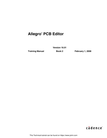
Cadence Virtuoso Schematic Design andCircuit Simulation TutorialIntroductionThis tutorial is an introduction to schematic capture and circuit simulation for ENGN1600 using CadenceVirtuoso. These courses use the NCSU FreePDK45 library for a 45nm technology. The NCSU libraryprovides the models for a 45nm Bulk‐Si technology from Fujitsu (details about the PDK can be found .This tutorial will guide you in the process of designing CMOS circuits using both user defined, transistor‐level schematics. It will also walk you through simulating the circuits in Spectre.In order to launch Cadence Virtuoso (either on the instructional machines or on your laptop), you willneed to connect to the Computation and Visualization cluster network at Brown (CCV). For additionaldetails on how to connect to CCV and launch Cadence, please refer to the CCV tutorial accessible fromthe ENGN1600 course webpage. Note that only the first part of this tutorial about logging on to the CCVmachines is relevant to you.Create your working environment ‐ Design LibraryAfter starting cadence, the first thing to do is create a new library. From the main Virtuoso window,select Tools Library Manager This will open the Library Manager (Figure 1) from which we canbrowse the existing libraries. From the Library Manager window go to File New Library Figure 1 Library Manager1Last update: Marc Powell, 9/9/2016
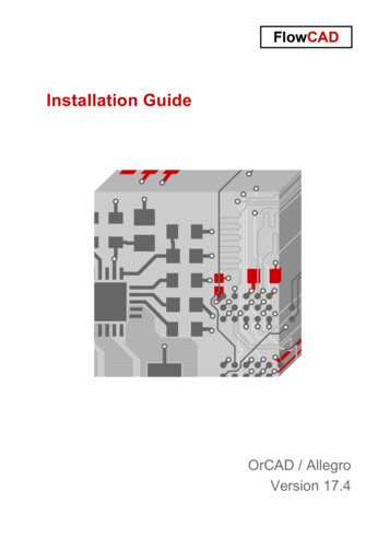
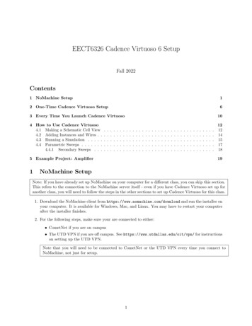
At this point you will be asked to choose a name for our library; for this tutorial use the nameTutorial lib (Figure 2). When asked which Technology File you would like to use for the libraryTutorial lib, check ‘Attach to an existing technology library’ (Figure 3), confirm and selectNCSU CellLib FreePDK45 from the Technology Library list. At this point you should be able to see aninstance of the new library in the Library Manager.Figure 2 Create New LibraryFigure 3 Select Technology file for the new library2Last update: Marc Powell, 9/9/2016
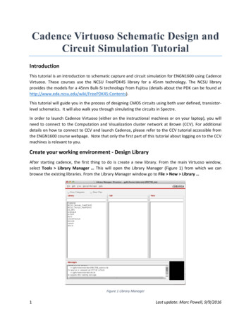
We will use this library for saving all the cells used in this tutorial. At this point we are ready to designour first schematic.Creating an inverter using transistors from the PDK libraryThroughout the course, you will be asked to create your own standard cell library. Using a standard celllibrary allows us to easily create digital circuits starting from a wide variety of common logic gates(inverters, NAND, NOR, latches). The first step in building a standard cell library is designing theschematic of the logic gates at the transistor level. The NCSU Devices FreePDK library provides fourdifferent technology flavors for both PMOS and NMOS devices: high‐performance (VTL), low operatingpower (VTG), low standby power (VTH) and thick‐oxide devices (THKOX) (Figure 13).Figure 4 Technology flavors for the FreePDK45 libraryThis tutorial will describe how to design a standard CMOS inverter using low‐standby power transistors(VTH). First, we need to create a new cell view in our Tutorial lib library. From the Library manager, goto File New Cell View From the New File window (Figure 5) you can select the destination Library(Tutorial lib), the Cell name (let’s call this cell low power inv) and the View (schematic).3Last update: Marc Powell, 9/9/2016
Figure 5 Create new schematic viewAfter confirming the creation of the new cell, a Schematic Editor window will appear (if a licensewarning message appears, click Yes). We now need to place and connect the components required forour inverter. Click on the Create Instance buttonwindow (Figure 6).or alternatively press 'i' to open the add instanceFigure 6 Add new instance4Last update: Marc Powell, 9/9/2016
The first step in creating the new schematic consists of adding the instances for a NMOS and a PMOStransistor. In the Add Instance window, type NCSU Devices FreePDK45 in the library field and thenselect NMOS VTH symbol view. Before placing the instance in the schematic editor check that the widthand length for the transistor are set properly (length 50nm and width 150nm as shown in Figure 7).Repeat the same procedure for the PMOS transistor but this time setting the width to 300nm. Afterhaving placed the transistor, add the vdd and gnd symbols from the analogLib library and connect theterminals together using the wire tool (). As we want to be able to interface this circuit with othercircuits, we need to add input and output ports. The input/output pins are created by clicking on theCreate Pin buttonor by pressing 'p'. When the Add Pin window appears, we need to select the PinName and the Pin direction (input or output). For example, the settings for the input of the inverter willlook as in Figure 8. The complete schematic should look similar to the one in Figure 9. After checkingand saving the schematic () go to Create Cellview From Cellview Confirm the settings inthe two following windows (Cellview from Cellview and Symbol Generation Options). This will open aSymbol Editor as in Figure 10. By clicking on Check and Save, a symbol view of our custom inverter willbe added to the library. With a little patience you can redraw the symbol (Figure 11) to look like aninverter using the drawing toolsThis symbol can be used to add inverters in a different circuit schematic, as we will see in the nextsection.Figure 7 Edit width for a NMOS transistor5Last update: Marc Powell, 9/9/2016
Figure 8 Add pins to the schematicFigure 9 Transistor schematic for a CMOS inverterFigure 10 Original symbol viewFigure 11 Better symbol view6Last update: Marc Powell, 9/9/2016
Create a test circuit schematic using our standard library cellOnce we have set up our standard library we can combine cells together and create bigger circuits oradd the components we need for a circuit simulation.First, select the Tutorial lib library and go to File New Cell View Create a new cell named gate inv.Once the Schematic Editor has started, select Create Instance. From here select Browse and using theLibrary Manager select your newly created library Tutorial lib and from there go to low power inv celland select the symbol view by double clicking. After confirming the selection, click on an empty spot inthe schematic editor for placing the instance of low power inv. Press Esc to stop the creation of newinstances.After placing the inverter symbol we need to create the input and output pins and the power supplyconnections. As before, use the Create Pin button (or press 'p') and connect the pins to the symbol ofthe inverter by using the wire tool.Note that even though no power supply connection has been specified yet, the cell low power invincludes implicit connections to the vdd! and gnd! nodes. We need then to explicitly connect thesenodes to a DC voltage generator. This can be done by separately instantiating the cells for vdd, gnd andvdc from the analogLib library. The first two cells represent the connection to vdd! and gnd! nodes,while vdc is a DC voltage generator. When a vdc instance is created we can specify the DC voltage acrossits terminal using the corresponding parameter as in Figure 12. The parameter window can always berecalled by selecting the desired instance and pressing 'q'. For this example, set the DC voltage to 1. Inorder to provide correct power supply to the inverters, these cells should be placed and connected asshown in Figure 13. Once we are done with the design of our schematic we can save the result andcheck for errors (i.e. dangling wires or misnamed pins/ports) by pressing the Check and Save buttonFigure 12 Setting voltage value for VDD generator7Last update: Marc Powell, 9/9/2016
Figure 13 Inverter subcircuit with power supply generatorCircuit simulation with SpectreSpectre is the circuit simulator in the Cadence tool suite (i.e., the Cadence version of SPICE). Circuitsimulation settings are created using the ADE (Analog Design Environment) tool. For this tutorial we willcharacterize the custom inverter designed in the previous section.Figure 14 Analog Design Environment windowIn order to start ADE for our simulation examples, from the schematic view of the gate inv cell, go toLaunch ADE L (Figure 14).Since we started ADE L from the gate inv schematic, it will automatically refer to this design. First, weneed to assign the models for the transistors in the schematic; click on the Model libraries button8Last update: Marc Powell, 9/9/2016
then click on the browse button (Figure 15) and select the file at the following su basekit/models/hspice/hspice nom.includeThis will select the nominal corner library. The other two available files are used for fast and slow cornerlibraries (where fast and slow refer to the relative threshold voltage variations).Figure 15 Model file selection windowApply the changes and return to the main window. Next we need to setup the stimuli for our circuit. Wewill first perform a DC sweep to extract the voltage transfer characteristic of the inverter. Click on theStimuli buttonand set the analog stimulus as in Figure 16:1.2.3.4.Select dc from the Function menu;Input Vin in the DC voltage field;Check the Enable flag;Apply changes;Note that we are assigning to the DC voltage a variable (Vin) rather than specific value so that we will beable to perform a DC sweep. For the simulator to recognize the variable, click on the Edit Variablesbutton and write Vin in the Name field and assign 1 to Value (Expr) (this value will be overwrittenduring the DC sweep). Click on Add and return to ADE main window.Figure 16 Setup stimulus for DC sweep analysis9Last update: Marc Powell, 9/9/2016
We now need to specify which analysis we want to perform. Click on the Choose analysis buttonand setup the parameters for a DC simulation as in Figure 17.Figure 17 DC sweep analysis settingsAs a last step we need to select the signals we want to be plotted in the output. Click on the SetupOutputs buttonand click on From Schematic. At this point you should see the schematic viewfrom which you can select the output node by clicking on the output net (wire). After the selection, thenet should be highlighted as in Figure 18 (the color may vary).Figure 18 Select output analysis nodesWe can now run the simulation by clicking on the Run button10Last update: Marc Powell, 9/9/2016
If everything runs without any error, at the end of the simulation the results will be plotted as in Figure19.Figure 19 Output plot for a DC sweep analysis of a CMOS inverterDC analysis is useful for characterizing the static behavior of a circuit. The dynamic behaviorcharacterization requires to run a transient analysis. Before setting up a new simulation, we need first tomodify the schematic of our circuit and add a load on the output node. Open the schematic view for thegate inv cell. Using the Create Instance toolselect the analogLib library and then the symbol viewfor the cap cell (capacitor). The capacitance value can be set to 1fF as in Figure 20. Connect one terminalof the capacitor to the output node and the other terminal to gnd as in Figure 21.11Last update: Marc Powell, 9/9/2016
Figure 20 Insert 1fF capacitorFigure 21 Schematic of inverter with capacitive loadAfter Check and Savereturn to the ADE window. Going from a DC simulation to a TRANsimulation will require adopting a different stimulus and setting the proper analysis. First, setup theanalog stimulus using a pulse function as in Figure 22 and apply the changes. Then, change thesimulation settings by creating a new analysis setup; click on Choose analysisandsettheparameters as in Figure 23. Since for the transient analysis we want to be able to compare input andoutput signals, you should add the input node using the Setup Outputs toolas done before forthe output node. Finally, uncheck the dc analysis in the main ADE window. If everything is set upproperly, your ADE window should look as in Figure 24.12Last update: Marc Powell, 9/9/2016
Figure 22 Setup stimulus as pulse function for transient simulationFigure 23 Transient analysis setup13Last update: Marc Powell, 9/9/2016
Figure 24 ADE window for transient simulationAfter running the simulation, the output plot should show two overlapping signals. To better distinguishbetween the two traces go to Graph Split Current Strip. This will generate a plot as in Figure 25.Figure 25 Plot of input and output trace for a single inverter14Last update: Marc Powell, 9/9/2016
We now want to get the time characteristic of the inverter as a function of the load capacitance. We canset ADE to run parametric simulations i.e., we can run the transient simulation for different values of aspecified parameter. Since we want to evaluate the output for different loads we will have toparameterize the capacitance value. First open the gate inv schematic, select the load capacitor andpress ‘q’. Replace the Capacitance parameter value with Cload and confirm the changes. In ADE, go tothe Edit Variablestool and select Copy From. This will add Cload to the list of Design Variables.Set the Value (Expr) to 1f and confirm the changes. We now want to set the simulator so that it willoutput the propagation delays (both for a rising and falling transition of the input signal). These valuesare not automatically generated at simulation time; therefore we need to create the expressions forcomputing the delays. This can be done by using two of the functions in the ADE calculator: getValue()and cross(). Go to the Setup Outputstool and create the following setup:1. Set Name (opt.) to tp1;2. Input the following line in the Expression field: (cross(getData("/Out" ?result"tran") 0.5 1 "falling") ‐ cross(getData("/In" ?result "tran") 0.5 1"rising"))3. Click Add;Repeat the procedure for a new output variable tp2 using the following expression:(cross(getData("/Out" ?result "tran") 0.5 1 "rising") ‐ cross(getData("/In"?result "tran") 0.5 1 "falling"))For the first example the first cross function will evaluate at the time the Out signal (getData("/Out"?result "tran")) will cross the threshold (set at 0.5 V) for the first falling edge.Once we have set the output variables we need to setup the parametric analysis. Go to Tools Parametric Analysis and set the parameters as in Figure 26 for running 5 different iterations withvalues from 1f to 1p. While in this case the values are automatically generated, you can specify whichvalues you want to use in the Inclusion List. Start the simulation on the selected values by clicking onFigure 26 Parametric Analysis settingsThe output should give you two plots: the first plot contains the two delays tp1 and tp2 as a function ofCload and the second contains input and output signals for different values of Cload as a function oftime.15Last update: Marc Powell, 9/9/2016
Note: Two tips for improving the visualization of the results:1. For the transient simulation, you can zoom in on a particular transition by shrinking the timewindow to the desired time step as in Figure 272. The delay functions are plotted as straight lines connecting the actual computed points. You canvisualize the single points by clicking on the plotted lines twice and select points/Solid/Fine inthe Type/Style field. The result should look as in Figure 28Figure 27 Select desired time window16Last update: Marc Powell, 9/9/2016
Figure 28 Plot single points from parametric simulation results17Last update: Marc Powell, 9/9/2016
Cadence Virtuoso Layout Editor andMentor Graphics Calibre VerificationThe design schematic allows us to explore and simulate the circuit design and have a first idea of theperformance of the circuit. The next step in the design flow is the layout. By drawing the layout of ourcircuit we can verify that the area requirements are met but also improve the circuit simulation byadding parasitic components to the netlist (these components are in fact, dependent on the physicalrealization of the circuit and cannot be determined only by its schematic description). Therefore, thelayout design is both a necessary step towards the physical fabrication of the circuit and a means forimproving the accuracy of the circuit simulations.In this tutorial we will create the layout for the inverter gate in the Tutorial lib. From the Librarymanager, select the low power inv cell and create a new Cell View with layout type (Figure 29).Figure 29 Create new layout cell viewThis will open the Layout L editor window (Figure 30). On the left side you should be able to see a list oflayers associated with the 45nm PDK. We will now design the layout for the PMOS and NMOS transistorsand connect them together to form a CMOS inverter.18Last update: Marc Powell, 9/9/2016
Figure 30 Layout L editor windowPMOS layout designThe PMOS sizes as defined in the schematic are W 300nm and L 50nm. When drawing the layout, youare not required to follow a specific order in drawing the layers. However, you should check the designrules for minimum size and spacing. The width of the transistor is given by the size of the active layeredge parallel to the poly layer that defines the gate. Since usually the transistors are drawn orienting thepoly gate vertically, we will start by drawing an active area with height equal to the W of the transistor:1. Select active from the list of layers on the left, making sure to select the one for drawing (drw);2. Press ‘r’ and click once in the black drawing window. Move the cursor until the ‘dY’ box in thetop shows ‘0.300’ (the sign depends on which way you move the cursor relative to the firstpoint) and ‘dX’ is roughly twice the size of ‘dY’.3. Once your rectangle has the desired size, click again to complete the shape.The PMOS is fabricated using a pimplant on a nwell. The pimplant overlaps with the active layer. Selectpimplant, and following the three steps above, create a layer exactly on top of the active layer. Whileyou are drawing, you can use the scroll wheel in your mouse to zoom in and out to improve theaccuracy. At this point you should have something that looks like Figure 31.19Last update: Marc Powell, 9/9/2016
Figure 31 Active and pimplant layers for a PMOS transistorIn order to create the transistor channel we need to place the poly layer. As before, create a rectangularshape but this time the width (‘dX’) should be exactly 0.050 and the height (‘dY’) should be bigger thanthe transistor width. In order to get the right size for the height we will need to use the design rules.Place the layer roughly in the middle of the active/pimplant layers. If you need to adjust the position ofyour layer, press ‘m’ and click on the layer you want to move. You will notice that you can adjust only inone direction. If you need to adjust the both vertical and horizontal position, you will need to repeat theoperation twice. The layout should now look as in Figure 32.While laying out a circuit, it is very important to follow the design rules in order to both properly designthe devices but also minimize the area required for a circuit. As an example, consider the design rulePOLY.3 which states that the Minimum poly extension beyond active should be 55nm (a list of the designrules can be found at http://www.eda.ncsu.edu/wiki/FreePDK45:Contents). Let’s go back to the layoutand zoom on the top portion of the drawing, where the poly extension is. A good way to check fordesign dimension is by using the ruler (press ‘k’). The ruler can be drawn as any other layer: click once atthe edge of the active/pimplant layer, move the cursor to the top corner of the poly layer and clickagain when the length is equal to 55nm (if you are too close to the poly edge it will lock to its corner).The result should look as in Figure 33. In my case, the poly extension is too short and would fail thedesign rule check (DRC). To fix the problem, we can stretch the layer (press ‘s’ and click on the edge thatyou want to move). You can repeat the procedure for the bottom side of the layout.20Last update: Marc Powell, 9/9/2016
Figure 32 Poly layerFigure 33 Fixing Poly layer extension using rulerWe will now place the contacts for drain and sources. By following the design rules you can adjust thedimension of the active/pimplant layers for minimum area (see Figure 34). A good way to follow designrules is to place the rulers as guidelines before drawing the layers. Figures 34‐36 show the additionalsteps for adding the nwell layer and the metal1 contacts.21Last update: Marc Powell, 9/9/2016
Figure 34 Add contacts for source and drainFigure 35 Adding nwell22Last update: Marc Powell, 9/9/2016
Figure 36 Adding metal1 contactsThe layout shown in Figure 36 is already a functional PMOS transistor. However, it does not match yetthe transistor used in the schematic. In fact, if we left the layout as is, we would have a PMOS VTLdevice. In order to get a PMOS VTH device as in the schematic, we need to add a High threshold implantlayer (vth) (overlap with the nwell layer) as in Figure 37.Figure 37 Complete layout for a PMOS VTH transistor23Last update: Marc Powell, 9/9/2016
You can repeat the same steps to design the NMOS transistor (remember that this time the widthshould be 150nm). The two transistors together should look like in Figure 38.Figure 38 Layout of NMOS VTH and PMOS VTH transistors for an inverterCombining these two transistors in a CMOS inverter requires making the input/output connections andadding Vdd and Gnd rails. The output connection can be easily made running a metal line from the drainof the PMOS to the drain of the NMOS. For the gate, we need to connect the two poly lines and make apoly contact. Contacts made on poly use the same layer as contacts on the active area. The PMOS andNMOS source will have to be connected to the Vdd and Gnd lines. The vertical spacing between the twopower‐supply metal lines is also known as cell pitch. The cell pitch defines an important feature of thestandard cell library. When creating a standard cell library it is good practice to keep the cell pitch andthe size of the power‐supply lines constant. This makes it easier to connect the layout of different cellstogether. The last step consists in adding the body contacts. These contacts are made creating apimplant in the pwell and a nimplant in the nwell. The active/implant layers are then connected to thepower rails using a contact on metal1. The final layout is shown in Figure 39. For this specific example, Ichoose a cell pitch of 1μm (however, depending on the size of the gates in your standard library, youmight have to choose a bigger spacing).24Last update: Marc Powell, 9/9/2016
Figure 39 Inverter final layoutLayout design verification with CalibreCalibre is a Mentor Graphics tool that works within the Cadence tool suite providing design verification.It provides Design Rules Check (DRC) and Layout vs Schematic comparison (LVS). All these functionalitiescan be recalled from Layout L through the Calibre menu.Design Rules Check (DRC)From Layout L, select Calibre Run nmDRC. This will launch Calibre Interactive directly from Virtuoso.After loading automatically the ruleset file, you can start the check pressing Run DRC on the left of theCalibre Interactive window. The results are shown in a new window where a green check mark meansno error, while a red x mark means that there is a violation of the design rule. If your design is error free,you can intentionally introduce an error to see how the DRC works. For instance, let’s remove the polyfrom the metal1‐poly contact as in Figure 40. After running the DRC again, the results should look as inFigure 41 (it is helpful to show only the rules unresolved rules by clicking on the filter button25).Last update: Marc Powell, 9/9/2016
Figure 40 Inverter layout missing poly on metal‐poly contactFigure 41 DRC results window26Last update: Marc Powell, 9/9/2016
The right portion of the Calibre window in Figure 41 will show a list of the errors in the layout (in thiscase there is only one). By clicking on the error index (1) the Layout Editor will automatically zoom in onthe portion of the layout where the error is.Layout vs Schematic (LVS)While the DRC allows us to check for errors in how the layout has been drawn, LVS checks whether thelayout matches the schematic. This control guarantees that the fabricated circuit will functionally matchthe designed schematic.In order to compare layout and schematic we need to add labels to the layout. Assuming we want toadd labels to the metal lines, select metal1 from the layer list. Then select Create Label and make surethat the settings match those in Figure 42. Confirm the selection and place the labels by clicking on thecorresponding metal1 layer. The result should look as in Figure 43.Figure 42 Creating labels for the inverterAt this point we can launch LVS by selecting Calibre Run nmLVS Before running LVS go to Input andcheck Export from schematic viewer (Figure 44), then click on Run LVS on the left side of the window.27Last update: Marc Powell, 9/9/2016
Figure 43 Adding labels to the inverter layoutFigure 44 Setup LVS netlist exportIf the layout matches the schematic you will see a happy smiley will pop up in the results window (Figure 45)28Last update: Marc Powell, 9/9/2016
Figure 45 LVS summary with no errors foundHow can we detect errors? Let’s change the layout so that it will not match the schematic anymore. Forinstance, let’s remove the metal connection between the body contact of the PMOS transistor and Vdd(Figure 46).Figure 46 Remove body connection to VddWhen we run nmLVS again the report will show more detailed results. In particular, if we look at thediscrepancy report for incorrect instances, we can see that Calibre identifies the problem as a misplacedbody connection (Figure 47)29Last update: Marc Powell, 9/9/2016
Figure 47 Report for missing body connection30Last update: Marc Powell, 9/9/2016
After starting cadence, the first thing to do is create a new library. From the main Virtuoso window, select Tools Library Manager , This will open the Library Manager (Figure 1) from which we can browse the existing libraries. From the Library Manager window go to File New Library , Figure 1 Library Manager ,