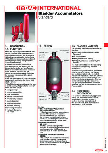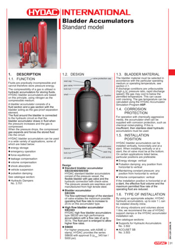
Transcription
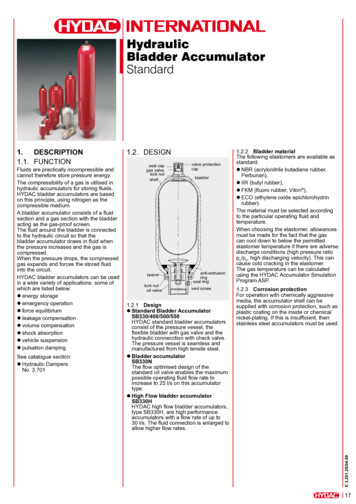
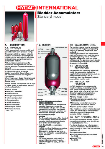
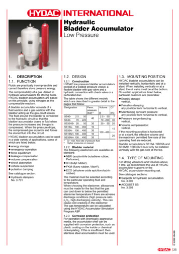
HydraulicBladder AccumulatorLow PressureFluids are practically incompressible andcannot therefore store pressure energy.The compressibility of a gas utilised inhydraulic accumulators for storing fluids.HYDAC bladder accumulators are basedon this principle, using nitrogen as thecompressible medium.A bladder accumulator consists of afluid section and a gas section with thebladder acting as the gas-proof screen.The fluid around the bladder is connectedto the hydraulic circuit so that thebladder accumulator draws in fluid whenthe pressure increases and the gas iscompressed. When the pressure drops,the compressed gas expands and forcesthe stored fluid into the circuit.HYDAC bladder accumulators can be usedin a wide variety of applications, some ofwhich are listed below:zzenergy storagezzemergency operationzzforce equilibriumzzleakage compensationzzvolume compensationzzshock absorptionzzvehicle suspensionzzpulsation dampingSee catalogue section:zzHydraulic dampersNo. 3.7011.3. MOUNTING POSITION1.2. Design1.2.1 ConstructionHYDAC low pressure bladder accumulatorsconsist of a welded pressure vessel, aflexible bladder with gas valve and ahydraulic connection with check valve or aperforated disc.The table shows the different modelswhich are described in greater detail in thepages that follow:DesignationSB402.5 . 50SB4070 . 220SB35HB- 20 . 50SB16A- 100 . 450SB35A- 100 . 450SB16AH- 100 . 450SB35AH- 100 . 4501)2)Perm.pressure[bar] 2)VolumeQ1)[l][l/s]2.5 - 5070 - 22020 - 504035163516357302015100 - 45020Q max. flow rate of pressure fluidHigher pressures on request1.2.2 Bladder materialThe following elastomers are available asstandard:zzNBR (acrylonitrile butadiene rubber,Perbunan),zzIIR (butyl rubber),zzFKM (fluoro rubber, Viton ),zzECO (ethylene oxide epichlorohydrinrubber).The material must be selected accordingto the particular operating fluid andtemperature.When choosing the elastomer, allowancesmust be made for the fact that the gascan cool down to below the permittedelastomer temperature if there are adversedischarge conditions (high pressure ratiop2/p0, high discharging velocity). This cancause cold cracking in the elastomer.The gas temperature can be calculatedusing the HYDAC Accumulator SimulationProgram ASP.1.2.3 Corrosion protectionFor operation with chemically aggressivemedia, the accumulator shell can besupplied with corrosion protection, such asplastic coating on the inside or chemicalnickel-plating. If this is insufficient, thenstainless steel accumulators must be used.HYDAC bladder accumulators can beinstalled vertically, horizontally and at aslant. When installing vertically or at aslant, the oil valve must be at the bottom.On certain applications listed below,particular positions are preferable:zzEnergy storage:vertical,zzPulsation damping:any position from horizontal to vertical,zzMaintaining constant pressure:any position from horizontal to vertical,zzPressure surge damping:vertical,zzVolume compensation:vertical.If the mounting position is horizontalor at a slant, the effective volume andthe maximum permitted flow rate of theoperating fluid are reduced.Bladder accumulators SB16A / SB35A andSB16AH / SB35AH must only be installedvertically with the gas side at the top.1.4. TYPE OF MOUNTINGFor strong vibrations and volumes above1 litre, we recommend the use of HYDACaccumulator supports or theHYDAC accumulator mounting set.See catalogue sections:zzSupports for hydraulic accumulatorsNo. 3.502zzACCUSET SBNo. 3.503E 3.202.1/04.091.Description1.1. Function25
2. Technicalspecifications2.1. EXPLANATORY NOTES2.1.1 Operating pressureSee tables(may differ from nominal pressure forforeign test certificates)2.1.2 Nominal volumeSee tables2.1.3 Effective gas volumeSee tables,based on nominal dimensions, this differsslightly from the nominal volume and mustbe used when calculating the effectivevolume.2.1.4 Effective volumeVolume of fluid which is available betweenthe operating pressures p2 and p1.2.1.5 Max. flow rate of the operatingfluidIn order to achieve the max. flow rate givenin the tables, the accumulator must bemounted vertically. It must be rememberedthat the residual fluid volume of approx.10% of the effective gas volume remains inthe accumulator.2.1.6 FluidsThe following sealing and bladdermaterials are suitable for the fluids listedbelow.MaterialNBRE 3.202.1/04.09ECOIIRFKM26FluidsMineral oils (HL, HLP, HFA,HFB, HFC), waterMineral oilPhosphate ester, waterChlorinated hydrocarbons,petrol2.1.7 Permitted operating temperatureThe permitted operating temperatures aredependent on the application limits of themetallic materials and the bladders.The standard valve bodies, gas valvesand accumulator shells are suitable fortemperatures from -10 C . 80 C.Outside these temperatures, specialmaterial combinations must be used.The following table shows the correlationbetween bladder material and re ranges-15 C . 80 C-50 C . 80 CNBR22-30 C . 80 CECO-30 C . 120 CIIRFKM-40 C . 100 C-10 C . 150 C2.1.8 Gas chargingAlways only charge with nitrogen class 4.5,filtered to 3 µm.If other gases are to be used, pleasecontact HYDAC for advice.Hydraulic accumulators must only becharged with nitrogen.Never use other gases.Risk of explosion!2.1.9 Limits for gas pre-chargepressurep0 0.9 p1with a permitted pressure ratio of:p2 : p0 4 : 1p2 max. operating pressurep0 gas pre-charge pressure2.1.10 Certificate codesCanada S1 2)ChinaA9EU member states U 1)JapanPSwitzerlandUUSA SOthers on request1)2)Alternative certificates possibleApproval required in the individual provincesOn no account must any welding, solderingor mechanical work be carried out on theaccumulator shell. After the hydraulic linehas been connected it must be completelyvented.Work on systems with hydraulicaccumulators (repairs, connectingpressure gauges etc) must only be carriedout once the pressure and the fluid havebeen released.Please read the operating manual!No. 3.201.CENote:Application examples, accumulator sizingand extracts from approvals regulations onhydraulic accumulators can be found in thefollowing catalogue section:zzAccumulatorsNo. 3.000
2.2. Model code(also order example)SB35 A – 100 F 7 / 112 U – 35 ANot all combinations are possibleWhen ordering spare bladders, please state smallest bladder connection port size at gas charging endDepending on type and pressure rating4)Standard materials, all other materials on request1)2)3)E 3.202.1/04.09SeriesTypeH high flowN increased flow, standard oil valve dimensionsA shock absorberB bladder top-repairableCombinations possible, e.g. HB - High flowwith a top-repairable bladderno details standardNominal volume [l]Fluid connectionA standard connection, thread with internal seal faceF flange connectionC valve mounting with screws on undersideE sealing surfaces on front interface (e.g. on thread M50x1.5 - valve)G male threadS special connection, to customer specificationGas side1 standard model2 back-up model3 gas valve 7/8-14UNF with M8 female thread4 5/8" gas valve5 gas valve M50x1.5 in accumulators smaller than 50 l6 7/8-14UNF gas valve7 M28x1.5 gas valve8 M16x1.5 gas valve9 special gas valve, to customer specificationMaterial code 1)Standard model 112 for mineral oilDepending on operating fluidOthers on requestFluid connection1 carbon steel2 high tensile steel3 stainless steel 3)6 low temperature steelAccumulator body0 plastic coated (internally)1 carbon steel2 chemically nickel-plated (internal coating)4 stainless steel 3)6 low temperature steelAccumulator bladder 2) 4)2 NBR203 ECO4 IIR (butyl)5 NBR21 (low temperature)6 FKM7 other9 NBR22Certification codeU PED 97/23/ECPermitted operating pressure [bar]ConnectionThread, codes for fluid connections: A, C, E, GA Thread to ISO 228 (BSP)B Thread to DIN 13 or ISO 965/1 (metric)C Thread to ANSI B1.1 (UN.-2B seal SAE J 514)D Thread to ANSI B1.20.1 (NPT)S special thread, to customer specificationFlange, codes for fluid connection: FA EN 1092-1 welding neck flangeB flange ASME B16.5C SAE flange 3000 psiD SAE flange 6000 psiS special flange, to customer specificationRequired gas pre-charge pressure must be stated separately!27
3. Low pressureaccumulators3.1 StandardBladderaccumulatorsSB40-2.5 . 503.1.2 DimensionsSB40-2.5 . 503.1.3 Spare partsSB40-2.5 . 503.1.1 DesignHYDAC standard low pressureaccumulators consist of:zzA welded pressure vessel which can betreated with various types of corrosionprotection for chemically aggressivefluids, or can be supplied in stainlesssteel.zzA bladder with gas valve. The bladdersare available in the elastomers listedunder point 2.1.zzA hydraulic connector with a perforateddisc which is held in place with retainingring.SB40-2.5 . 50Permitted operating pressure 40 bar(PED 97/23/EC)Nominal Eff. gas Wt. ABCvolume volume[l][l][kg] [mm] [mm] 063233.53813635048.6521875E 3.202.1/04.09Nom.vol.[l]2.551020325028Ø D J Thread K *SW Q 1)ThreadISO[mm] DIN 13 ISO 228 [mm] [l/s]108M100x2 G 236721968 2)* Item 16 must be ordered separately1)Q max. flow rate of operating fluid(at approx. 0.5 bar pressure drop via adapter)2)Lock nutDescription ItemBladder kit 1)consisting of:Bladder2Gas valve insert*3Lock nut4Seal cap5Valve protection cap6O-ring7Seal kitconsisting of:O-ring7Vent screw13Seal ring14O-ring15Repair kit 1)consisting of:Bladder kit (see above)Seal kit (see above)Hydraulic connector assemblyconsisting of:Perforated disc10Anti-extrusion ring11Retaining ring12Vent screw13Seal ring14O-ring15* available separately1)When ordering spare bladders, please state smallestbladder connection port size at gas charging end.Item 1 not available as a spare part.
3.2. BladderaccumulatorSB40-70 . 2203.2.2 DimensionsSB40-70 . 2203.2.3 Spare partsSB40-70 . 220SB40-70 . 220Permitted operating pressure 40 bar(PED 97/23/EC)Nominal Eff. gasWt.ABvolume volumemax.[l][l][kg][mm] [mm]706494119910011111316291301331331879 13719019216920862202201932330Nominal Cvolume[l][mm]70100130781902201)ØD[mm]J Thread Q 1)ISO 228[l/s]356G 2 1/2407Q max. flow rate of operating fluid30Description ItemBladder kit 1)consisting of:Bladder2Gas valve insert*3Lock nut4Seal cap5Valve protection cap6O-ring7Seal kitconsisting of:O-ring7Washer15O-ring16Vent screw19Support ring23O-ring27Repair kit 1)consisting of:Seal kit (see above)Bladder kit (see above)Anti-extrusion ring14Oil valve assemblyconsisting of:Valve assembly (items 9-13)9Anti-extrusion ring14Washer15O-ring16Spacer17Lock nut18Vent screw19Support ring23* available separately1)When ordering spare bladders, please state smallestbladder connection port size at gas charging end.Item 1 not available as a spare part.Item 19 for NBR/Carbon steelSeal ring (Item 20) includedE 3.202.1/04.093.2.1 DesignHYDAC low pressure accumulators, typeSB40-70 . 220 consist of:zzA welded pressure vessel which iscompact and yet suitable for high flowrates and large volumes.The pressure vessel is manufactured incarbon steel or in stainless steel.zzAn accumulator bladder with gas valve.zzA hydraulic connector with check valve.29
3.3. Low pressureaccumulatorsSB16/35A and SB16/35AH3.3.2 DimensionsSB16/35A, SB16/35AH3.3.1 DesignHYDAC low pressure bladderaccumulators for large volumes, typeSB35A and SB16A are in a weldconstruction in carbon steel or stainlesssteel.The hydraulic outlet is covered by aperforated disc which prevents the flexiblebladder extruding from the shell. Thebladder is top-repairable.The bladder accumulators have aconnection assembly suitable formax. 15 l/s (SB16/35A)or max. 70 l/s (SB16/35AH) at a Dp of2 bar.3.3.3 Spare partsSB16/35A, SB16/35AHWelding neck flangeDN100 PN16/PN40EN1092-1/11(others on request)Welding neck flangeDN80 PN16/PN40EN1092-1/11(others on request)SB16/35APermitted operating pressure 16/35 bar(PED 97/23/EC)Nominal Eff.volume gasvolume[l][l]WeightSB16A SB35A 80132017202240263599143187278392480[kg]Nominal Bvolume (approx.)[mm][l]SB16A SB35A1003904031504905032006856983009759883751250 12634501465 022302325C(approx.)[mm]DN*SB16ASB35A185198100E 3.202.1/04.09SB16/35AHPermitted operating pressure 16/35 bar(PED 97/23/EC)30Nominal Eff.volume gasvolume[l][l]SB16AH SB35AH SB16AH 78392480Weight[kg]Nominal Bvolume (approx.)[mm][l]SB16AH SB35AH1004574651505575652008428503001092 11003751342 50* to EN1092-1/11 / PN16 or PN40Others on request96511651425187323152710DN*80Description ItemBladder2Lock nut3O-ring11Seal ring13Vent screw18O-ring19Retaining ring21O-ring25
3.4. HIGH FLOWBLADDERACCUMULATORSSB35HB3.4.3 Spare partsSB35HB3.4.2 DimensionsSB35HB3.4.1 DesignHYDAC high flow bladder accumulatorstype SB35HB are high performanceaccumulators for flow rates of up to 20 l/sat 2 bar Dp.They consist of a pressure vessel in a weldconstruction and a flexible bladder withgas valve.The pressure vessel contains a fixedperforated disc, permitting a high flow ratethrough its large free cross-section. Foruse with chemically aggressive fluids, theshell can be manufactured in stainlesssteel. See point 2.1 for bladder materials.thebladderistoprepairable.Welding neck flangeDN50 / PN40EN1092-1/11(others on request)Nominalvolume[l]Eff. 35669108115912091Nominalvolume[l]2032501)2)4. NOTEThe information in this brochure relates tothe operating conditions and applicationsdescribed.For applications and operating conditionsnot described, please contact the relevanttechnical department.Subject to technical modifications.CJThread[mm] [mm] ISO 22863ØD219G 1/278Q max. flow rate of pressure fluidLock nutSWQ1)
1 litre, we recommend the use of HYDAC accumulator supports or the c accumulator mounting set. See catalogue sections: z supports for hydraulic accumulators no. 3.502 z Accuset sB no. 3.503. 26 E 3.202.1/04.09 2. tEchnical spEcifications 2.1. eXPLAnAtoRY notes 2.1.1 operating pressure see tables (may differ from nominal pressure for foreign test certificates) 2.1.2 nominal volume see tables 2 .