Transcription
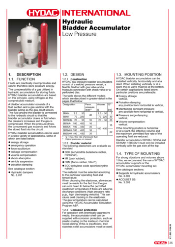
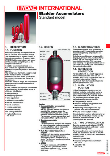
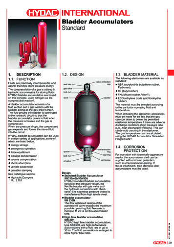
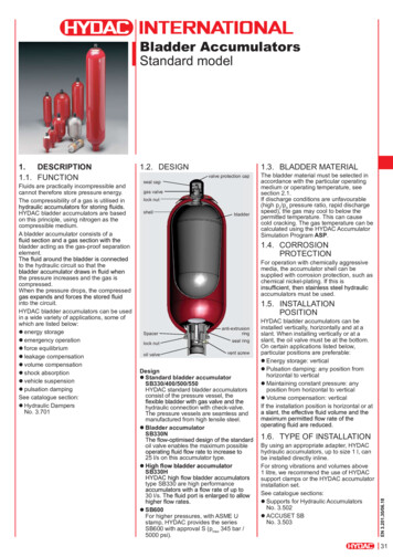
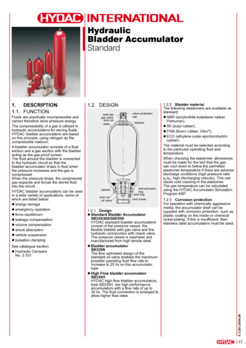
HydraulicBladder AccumulatorStandardFluids are practically incompressible andcannot therefore store pressure energy.The compressibility of a gas is utilised inhydraulic accumulators for storing fluids.HYDAC bladder accumulators are basedon this principle, using nitrogen as thecompressible medium.A bladder accumulator consists of a fluidsection and a gas section with the bladderacting as the gas-proof screen.The fluid around the bladder is connectedto the hydraulic circuit so that thebladder accumulator draws in fluid whenthe pressure increases and the gas iscompressed.When the pressure drops, the compressedgas expands and forces the stored fluidinto the circuit.HYDAC bladder accumulators can be usedin a wide variety of applications, some ofwhich are listed below:zzenergy storagezzemergency operationzzforce equilibriumzzleakage compensationzzvolume compensationzzshock absorptionzzvehicle suspensionzzpulsation dampingSee catalogue section:zzHydraulic DampersNo. 3.7011.2. Designseal capgas valvelock nutshellspacerlock nutoil valvevalve protectioncapbladderanti-extrusionringseal ringvent screw1.2.1 DesignzzStandard Bladder AccumulatorSB330/400/500/550HYDAC standard bladder accumulatorsconsist of the pressure vessel, theflexible bladder with gas valve and thehydraulic connecction with check valve.The pressure vessel is seamless andmanufactured from high tensile steel.zzBladder accumulatorSB330NThe flow optimised design of thestandard oil valve enables the maximumpossible operating fluid flow rate toincrease to 25 l/s on this accumulatortype.zzHigh Flow bladder accumulatorSB330HHYDAC high flow bladder accumulators,type SB330H, are high performanceaccumulators with a flow rate of up to30 l/s. The fluid connection is enlarged toallow higher flow rates.1.2.2 Bladder materialThe following elastomers are available asstandard:zzNBR (acrylonitrile butadiene rubber,Perbunan),zzIIR (butyl rubber),zzFKM (fluoro rubber, Viton ),zzECO (ethylene oxide epichlorohydrinrubber).The material must be selected accordingto the particular operating fluid andtemperature.When choosing the elastomer, allowancesmust be made for the fact that the gascan cool down to below the permittedelastomer temperature if there are adversedischarge conditions (high pressure ratiop2/p0, high discharging velocity). This cancause cold cracking in the elastomer.The gas temperature can be calculatedusing the HYDAC Accumulator SimulationProgram ASP.1.2.3 Corrosion protectionFor operation with chemically aggressivemedia, the accumulator shell can besupplied with corrosion protection, such asplastic coating on the inside or chemicalnickel-plating. If this is insufficient, thenstainless steel accumulators must be used.E 3.201.25/04.091.Description1.1. Function17
1.3. MOUNTING POSITIONHYDAC bladder accumulators can beinstalled vertically, horizontally and at aslant. When installing vertically or at aslant, the oil valve must be at the bottom.On certain applications listed below,particular positions are preferable:zzEnergy storage:vertical,zzPulsation damping:any position from horizontal to vertical,zzMaintaining constant pressure:any position from horizontal to vertical,zzVolume compensation:vertical.If the mounting position is horizontalor at a slant, the effective volume andthe maximum permitted flow rate of theoperating fluid are reduced.1.4. TYPE OF MOUNTINGBy using an appropriate adapter, HYDACaccumulators, up to size 1 l, can bemounted directly inline.For strong vibrations and volumes above1 l, we recommend the use of HYDACaccumulator supports or the HYDACaccumulator mounting set.See catalogue sections:zzSupports for Hydraulic AccumulatorsNo. 3.502zzACCUSET SBNo. 3.5032. Technicalspecifications2.1. EXPLANATORYNOTES2.1.1 Operating pressureSee tables(may differ from nominal pressure forforeign test certificates)2.1.2 Nominal volumeSee tables2.1.3 Effective gas volumeSee tablesbased on nominal dimensions, this differsslightly from the nominal volume and mustbe used when calculating the effectivevolume.2.1.4 Effective volumeVolume of fluid which is available betweenthe operating pressures p2 and p1.2.1.5 Max. flow rate of operating fluidIn order to achieve the max. flow rate givenin the tables, the accumulator must bemounted vertically. It must be rememberedthat a residual fluid volume of approx. 10%of the effective gas volume remains in theaccumulator.2.1.6 FluidsThe following sealing and bladdermaterials are suitable for the fluids listedbelow.MaterialNBR20ECOIIRFKMFluidsMineral oils (HL, HLP,HFA, HFB, HFC), waterMineral oilPhosphate esterChlorinated hydrocarbons, petrol2.1.7 Permitted operating temperatureThe permitted operating temperatures aredependent on the application limits of themetallic materials and the bladders.The standard valve bodies, gas valvesand accumulator shells are suitable fortemperatures from -10 C . 80 C.Outside these temperatures, specialmaterial combinations must be used.The following table shows the correlationbetween bladder material and applicationtemperature.E mperature ranges-15 C . 80 C-50 C . 80 C-30 C . 80 C-30 C . 120 C-40 C . 100 C-10 C . 150 C2.1.8 Gas chargingAlways only charge with nitrogen class 4.5,filtered to 3 µm.If other gases are to be used, pleasecontact HYDAC for advice.Hydraulic accumulators must only becharged with nitrogen.Never use other gases.Risk of explosion!2.1.9 Limits for gas pre-chargepressurep0 0.9 p1with a permitted pressure ratio of:p2 : p0 4 : 1p2 max. operating pressurep0 gas pre-charge pressure2.1.10 Certificate codesChinaA9EU member states U 1)JapanPCanadaS1 2)Switzerland UUSASothers on request1)2)Alternative certificates possibleApproval required in the individual provincesOn no account must any welding, solderingor mechanical work be carried out on theaccumulator shell. After the hydraulic linehas been connected it must be completelyvented.Work on systems with hydraulicaccumulators (repairs, connectingpressure gauges etc) must only be carriedout once the pressure and the fluid havebeen released.Please read the operating manual!No. 3.201.CENote:Application examples, accumulator sizingand extracts from approvals regulations onhydraulic accumulators can be found in thefollowing catalogue section:zzAccumulatorsNo. 3.000
2.2. Model code(also order example)SeriesTypeH high flowN increased flow, standard oil valve dimensionsA shock absorberP pulsation damperS suction flow stabiliserB bladder top-repairableCombinations possible, e.g. HB - High flow with a top-repairable bladderPH - pulsation damper with high flow rate.No details standardNominal volume [l]Fluid connectionA standard connection, thread with internal seal faceF flange connectionC valve mounting with screws on undersideE sealing surfaces on front interface (e.g. on thread M50x1.5 - valve)G male threadS special connection, to customer specificationGas side1 standard model 4)2 back-up model3 gas valve 7/8-14UNF with M8 female thread4 5/8" gas valve5 gas valve M50x1.5 in accumulators smaller than 50 l6 7/8-14UNF gas valve7 M28x1.5 gas valve8 M16x1.5 gas valve9 special gas valve, to customer specificationMaterial code 1)Standard model 112 for mineral oilDepending on operating fluidothers on requestFluid connection1 carbon steel2 high tensile steel3 stainless steel 3)6 low temperature steelAccumulator shell0 plastic coated (internally)1 carbon steel2 chemically nickel-plated (internal coating)4 stainless steel 3)6 low temperature steelAccumulator bladder 2)2 NBR203 ECO4 IIR (butyl)5 NBR21 (low temperature)6 FKM7 other9 NBR22Certification codeU PED 97/23/ECPermitted operating pressure [bar]ConnectionThread, codes for fluid connections: A, C, E, GA Thread to ISO 228 (BSP)B Thread to DIN 13 or ISO 965/1 (metric)C Thread to ANSI B1.1 (UN.-2B seal SAE J 514)D Thread to ANSI B1.20.1 (NPT)S special thread, to customer specificationFlange, codes for fluid connection: FA DIN flangeB flange ANSI B16.5C SAE flange 3000 psiD SAE flange 6000 psiS special flange, to customer specificationPre-charge pressure p0 [bar] at 20 C must be stated separately, if required!Not all combinations are possibleWhen ordering spare bladders, please state smallest bladder connection port sizeDepending on type and pressure rating4)Gas valve type in SB 50 l 7/8 - 14 UNF, in SB 50 l M50x1.51)2)3)E 3.201.25/04.09SB330 H – 32 A 1 / 112 U – 330 A 05019
ABmax.[l][bar] [l][kg]0.54000.52.83304.511.05508.53302.4 102.55502.5 13.5standard33011.543.740015.555504.9 2363305.7 152)3309.3 2510standard9.3 31.5N33010 H934.54009.3 37.5standard5008.8 41standard43N3301312H46standard 40049standard18.4 50.5N33017.5 53.520 H40018.4 63.5standard5001775.5standard23.6 69.024 N330H2472standard33.9 87N33032 H32.5 9040033.9 104.5standard50033.5 12750NHE 500standard 330C120.514248.3 16960 18285 221105 255133 305170 396201 485Q max. flow rate of pressure fluidslimline version, for confined spacesØD Jmax. thread[mm] [mm] [mm] [mm]27033.5 95.557302118334 68121531 63118539 6812158419 631738675317286812163173568 103603 138572 103585 775868660 103695 138666 10358896 103931 138896 103901 771062 1032292332412292335822968233241582291097 138Ø E SW1411 1031446 1381411 1031446 771966 1381931 1031951 77115614061656138197620062306ISO228Q 1)G 3/4[mm] [mm] [l/s]50G1G 1 1/4G1G 1 1/467G1G 1 1/4G 1 G 2 1/2 12590152530G21007015G210070G2103 70G 2 1/2 125 90G2100 70G2100 70G 2 1/2 125 90100 70G2110 75G2100 70G 2 1/2 125 90117.5 1931 10347.5DimensionsWeightEffective gas volumeMax. operating pressure(PED 97/23/EC)ValveNominal volumes3.DIMENSIONS AND SPARE PARTS3.1. DIMENSIONSG2100 70G 2 1/2 125 90100 70G2110 75G2100 70G 2 1/2 125 5668G 2 1/2 125 9040630adapterforspecialthreads
3.2. Spare partsSB330/400/440/500/550SB330H / SB330NDescriptionBladder kitconsisting of:BladderGas valve insert*Lock nutSeal capValve protection capO-ringSeal kitconsisting of:O-ringWasherO-ringVent screwSupport ringO-ringRepair kit 1)consisting of:Bladder kit (see above)Seal kit (see above)Anti-extrusion ringOil valve assemblyconsisting of:Valve assembly (items 9-13)Anti-extrusion ringWasherO-ringSpacerLock nutVent screwSupport ringItem23456771516192327149141516171819233.3. REPAIR KITSNBR, carbon steelNom. volume: 0.5 . 200 litresStandard gas valveNom. volume [l]Part 0860211210010 5130031175161600311751720003117558*) slimline version for confined spacesothers on request* available separately1)When ordering please state smallest bladderconnection port size.Item 1 not available as a spare part.Item 19 for NBR/Carbon steel:seal ring (item 20) includedItem 25 must be ordered as an accessory(see Point 4).Detail "X"SB330/400 – 0.5 . 6 lE 3.201.25/04.09SB330/400/500 – 10 . 200 l andSB330H – 10 . 200 lSB550 – 1 . 5 l21
4.ACCESSORIES FOR BLADDERACCUMULATORS4.1. ADAPTERS (gas side)4.1.2 Pressure gauge model with shut-off valveGas side connection on the bladder accumulator for permanentmonitoring of the pre-charge pressure with shut-off option.To monitor the accumulator pre-charge pressure, HYDAC offers aselection of gas side adapters.These must be ordered separately4.1.1 Pressure gauge model:Gas side connection on the bladder accumulator for permanentmonitoring of the pre-charge pressuregauge Ø100gauge shut-offvalveGaugeGaugeindication rangePart no.––0 - 10 bar006144200 - 60 bar006068860 - 100 bar006068870 - 160 bar006068880 - 250 bar006068890 - 400 bar00606890* pmax 400 barAdapter body* AdapterassemblyPart no.Part 80210021702102117GaugeGaugeindication rangePart no.––0 - 25 bar006313800 - 60 bar006067710 - 100 bar006067720 - 160 bar006067730 - 250 bar006067740 - 400 bar00606775E 3.201.25/04.09* pmax 400 bar22approx.pressure gaugeØ63Adapter body* AdapterassemblyPart no.Part 00319415402103226
4.1.3 Remote monitoring of the pre-charge pressureTo monitor the pre-charge pressure in hydraulic accumulatorsremotely, gas side adapters with pressure gauge and mountingholes are available.In order to connect these adapters directly with the hydraulicaccumulator using appropriate lines, accumulator adapters arealso available for connection at the top (see diagram 1) or forside-connection (see diagram 2).4.2. ADAPTERS FOR STANDARD BLADDERACCUMULATORS (fluid side)to connect the bladder accumulator to pipe fittings. These areavailable separately.O-ring2 holespressure gaugeØ63approx.Gaugeindicationrange–0 - 10 bar0 - 60 bar0 - 100 bar0 - 160 bar0 - 250 bar0 - 400 barGaugePart 6890Adapter body* AdapterassemblyPart no.Part 10309582203095823D1Accum.conn.*(ISO228BSP)G 3/4G 1 1/4* pmax 400 barG2D2[mm]G 3/8G 1/2G 3/8G 1/2G 3/4G1G 1/2G 3/4G 1 1/4G 1 4162022SW OPart 840211012402104853021048490210711302105905* others on request5. NOTEO-ring 11x2The information in this brochure relates to the operatingconditions and applications described. For applications andoperating conditions not described, please contact the relevanttechnical department. Subject to technical modifications.Diagram 2D1ThreadedconnectionD2ISO228- G 1/425ISO228- G 3/828ISO228- G 1/234T[mm]14* pmax 400 bar16Adapterbody*Part 4AdapterassemblyPart no.021094810
See catalogue section: z Hydraulic Dampers no. 3.701 1.2. DeSign seal cap lock nut shell gas valve valve protection cap bladder spacer anti-extrusion ring seal ring lock nut oil valve vent screw 1.2.1 Design z standard Bladder Accumulator sB330/400/500/550 HYDAc standard bladder accumulators consist of the pressure vessel, the flexible bladder with gas valve and the hydraulic connecction with .