Transcription
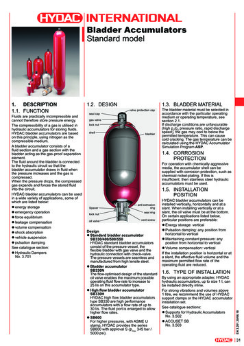
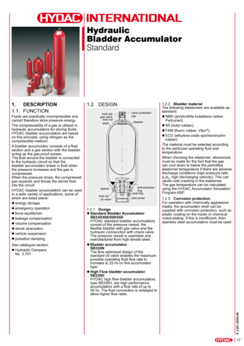
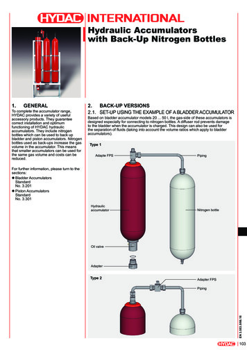
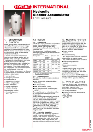
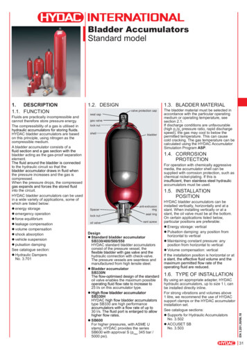
Bladder AccumulatorsStandard model1.DESCRIPTION1.1. FUNCTIONFluids are practically incompressible andcannot therefore store pressure energy.The compressibility of a gas is utilised inHYDAC bladder accumulators are basedon this principle, using nitrogen as thecompressible medium.A bladder accumulator consists of a1.2. DESIGN1.3. BLADDER MATERIALvalve protection capseal capgas valvelock nutshellbladderThe bladder material must be selected inaccordance with the particular operatingmedium or operating temperature, seesection 2.1.If discharge conditions are unfavourable(high p2/p0 pressure ratio, rapid dischargespeed), the gas may cool to below thepermitted temperature. This can causecold cracking. The gas temperature can becalculated using the HYDAC AccumulatorSimulation Program ASP.bladder acting as the gas-proof separationelement.1.4. CORROSIONPROTECTIONto the hydraulic circuit so that theFor operation with chemically aggressivemedia, the accumulator shell can besupplied with corrosion protection, such aschemical nickel-plating. If this isthe pressure increases and the gas iscompressed.When the pressure drops, the compressedinto the circuit.HYDAC bladder accumulators can be usedin a wide variety of applications, some ofwhich are listed below:energy storageemergency operationforce equilibriumleakage compensationvolume compensationshock absorptionvehicle suspensionpulsation dampingSee catalogue section:Hydraulic DampersNo. 3.701accumulators must be used.1.5. INSTALLATIONPOSITIONSpaceranti-extrusionringlock nutoil valveseal ringvent screwDesignStandard bladder accumulatorSB330/400/500/550HYDAC standard bladder accumulatorsconsist of the pressure vessel, thehydraulic connection with check-valve.The pressure vessels are seamless andmanufactured from high tensile steel.Bladder accumulatorSB330Noil valve enables the maximum possible25 l/s on this accumulator type.SB330Htype SB330 are high performance30 l/s.SB600For higher pressures, with ASME Ustamp, HYDAC provides the seriesSB600 with approval S (pmax 345 bar /5000 psi).HYDAC bladder accumulators can beinstalled vertically, horizontally and at aslant. When installing vertically or at aslant, the oil valve must be at the bottom.On certain applications listed below,particular positions are preferable:Energy storage: verticalPulsation damping: any position fromhorizontal to verticalMaintaining constant pressure: anyposition from horizontal to verticalVolume compensation: verticalIf the installation position is horizontal or at1.6. TYPE OF INSTALLATIONBy using an appropriate adapter, HYDAChydraulic accumulators, up to size 1 l, canbe installed directly inline.For strong vibrations and volumes above1 litre, we recommend the use of HYDACsupport clamps or the HYDAC accumulatorinstallation set.See catalogue sections:Supports for Hydraulic AccumulatorsNo. 3.502ACCUSET SBNo. 3.50331
2.SPECIFICATIONS2.1. EXPLANATIONS, NOTES2.1.5 Effective volume2.1.1 Operating pressuresee tables in section 3. (PED)May differ from nominal pressure for other2.1.62.1.2 Permitted operating temperatureof the hydraulic accumulator-10 C . 80 Cstandard design, others on request2.1.3 Nominal volumesee tables in section 3.the operating pressures p2 and p1.given in the tables, the accumulator mustbe installed vertically. It must be noted thatthe effective gas volume remains in theaccumulator.is not applicable in all operating conditions.2.1.7 Working temperature andoperating mediumThe permitted working temperature of abladder accumulator is dependent on theapplication limits of the metal materialsand the bladder. Outside this temperaturerange, special materials must be used. Theoperating medium must also be taken intoaccount.The following table displays a selectionof elastomer materials including max.temperature range and a rough overviewPleasecontact us for help in selecting a suitableelastomer.2.1.4 Effective gas volumesee tables in section 3.Based on nominal dimensions, this differsslightly from the nominal volume and mustvolume.MaterialsMaterialcode 1)Temperature rangeNBR2-15 C . 80 C5-50 C . 50 C9-30 C . 80 Cgroups HFA, HFB, HFCSynthetic esters (HEES)WaterSea waterEthylene oxide 3epichlorohydrinrubber-30 C . 120 CMineral oil (HL, HLP)ECOIIRAcrylonitrilebutadienerubberButyl rubber42)Resistant toMineral oil (HL, HLP)group HFBSynthetic esters (HEES)WaterSea water-50 C . 100 Cgroup HFCWaterFKMFluorine rubber 6-10 C . 150 CMineral oil (HL, HLP)HFD,Synthetic esters (HEES)FuelsAromatic hydrocarbonsInorganic acids1)2)32see section 2.2. Model code, material code, accumulator bladderothers on requestNot resistant toAromatic hydrocarbonsChlorinated hydrocarbons(HFD-S)Amines and ketonesHFD-RFuelsAromatic hydrocarbonsChlorinated hydrocarbons(HFD-S)Amines and ketonesHFD-Rgroups HFA and HFCFuelsMineral oils and mineral greasesSynthetic esters (HEES)Aliphatic, chlorinated andaromatic hydrocarbonsFuelsAmines and ketonesAmmoniaSkydrol and HyJet IVSteam
2.1.8 Gas chargingHydraulic accumulators must only becharged with nitrogen.Never use other gases.Risk of explosion!In principle, only use nitrogen of at leastIf other gases are to be used, pleasecontact us for advice.2.1.9 Limits for gas pre-chargepressurep0 0.9 p1with a permitted pressure ratio of:p2 : p0 4 : 1p2 max. operating pressurep0 pre-charge pressure2.1.10CountryEU member statesAustraliaBelarusCanadaChinaHong KongIcelandJapanKorea (Republic)New ZealandNorwayRussiaSouth AfricaSwitzerlandTurkeyUkraineUSA2.1.11 Gas-side connectionstandard modelcode (AKZ)UF 1)A6S1 1)A9A9UPA11TUA6S2UUA10SSeriesVolume[l]SB330 /SB4005/8-18UNF7/8-14UNFM50x1.5 / 7/8-14UNF10 . 50 M50x1.5 / 7/8-14UNFSB500 /SB600SB550Gas valve type1 . 5 7/8-14UNFother pressure ranges on request registration required in the individual territories orprovincesothers on request1)On no account must any welding, solderingor mechanical work be carried out on theaccumulator shell. After the hydraulic linehas been connected it must be completelyvented.Work on systems with hydraulicaccumulators (repairs, connectingpressure gauges etc.) must only be carriedbeen released.The operating instruction must beobserved!No. 3.201.BANotice:Application examples, accumulator sizing,instructions and extracts from approvalsand transport regulations relating tohydraulic accumulators can be found in thefollowing catalogue section:HYDAC Accumulator TechnologyNo. 3.00033
3.2.2. MODEL CODENot all combinations are possible. Order example.For further information, please contact HYDAC.DIMENSIONS ANDSPARE PARTS3.1. DIMENSIONSSB330 (H) – 32 A 1 / 112 U – 330 A 050SeriesType codeno details standardA shock absorberP pulsation damper 3)B bladder top-removableDA bladder integrity system, industry model(others on request)L light weightCombinations must be agreed with HYDAC.Nominal volume [l]Fluid connectionA standard connection, thread with internal seal faceC valve mounting with screws on undersideE sealing surfaces on front interface(e.g. on thread M50x1.5 - valve)G male threadGas side1 standard design (see section 2.1.11)2 back-up version 4)3 gas valve 7/8-14UNF with M8 internal thread4 gas valve 7/8-14UNF with gas valve connection 5/8-18UNF5 gas valve M50x1.5 in accumulators smaller than 50 l6 7/8-14UNF gas valve7 M28x1.5 gas valve8 M16x1.5 gas valve(with M14x1.5 bore in gas valve)Material codedependent on operating mediumstandard model 112 for mineral oilsothers on requestFluid connection1 carbon steel2 high tensile steel3 stainless steel 2)6 low temperature steelAccumulator shell0 plastic coated (internally)1 carbon steel2 chemically nickel-plated (internal coating)4 stainless steel 2)6 low temperature steelAccumulator bladder 1)2 NBR 5)3 ECO4 IIR5 NBR 5)6 FKM7 other9 NBR 5)U European Pressure Equipment Directive (PED)Permitted operating pressure [bar]ABCD thread to ISO 228 (BSP)thread to DIN13 or ISO 965/1 (metric)thread to ANSI B1.1 (UN.-2B seal SAE J 514)thread to ANSI B1.20.1 (NPT)Pre-charge pressure p0 [bar]) at 20 C, must be stated clearly, if required!when ordering a replacement bladder, state diameter of the smaller shell portdependent on type and pressure rangesee catalogue section Hydraulic Dampers, No. 3.7014)see catalogue section Hydraulic accumulators with back-up nitrogen bottles, No. 3.5535)observe temperate ranges, see section 2.1.1)2)3)34adapter,see section 4.2.
NBR, carbon steelNominal SB330Max. operating pressure(AKZ) U[bar] Part no.400 3047163330 3047162550 3110531330 3047165550 3068916330 3047166400 3017905550 3090654330 3047168330 30471703047172330 31566323079081400 3107393500 3130252––3047173330 ––400 –3047174330 31629823092659400 3115007500 3118156––3047175330 ––3047176330 32208993059515400 3125141500 3760577––3047177330 31856043089605400 3114662500 3130253––330 3341217330 –330 3098489330 –330 –330 –(AKZ) S[bar] Part �––––262 3141237––––––––345 332265––––––––262 3117153––––––––345 332266––––––262 3117154––––290 –––345 332267262 362904––––––––345 332268––––––––––––Eff. 57676467[mm] [mm] ISO 22833.5 96G 3/4115G 3/456123 G 1115G 1 1/456123 G 13.74126556170G 1 G1G 1 1/4G 1 1/46767674550509.3582101G21007099.3617578136G 2 1/2125906101015253017183133343841G21007015G210070G 2 1/2G21251009070G210070G 2 1/2125100907011075G210070G 2 1/212590G210070G 2 1/2125100907011075G210070G 2 1/21259070G2100G 2 1/2G 2 1/2G 2 1/2G 2 1/2G 2 1/2G 2 292345622923423.632.533.9229ØESW[mm]505067[mm] [l/s] [kg]32443247456105010114561467Q 1) Weight23410169517.518.456ØD Jmax. 281371671602002342833454031)2)35
3.2. SPARE PARTSSB330/400/500/550/600SB330H / SB330NDescriptionItemBladder assembly 1)consisting of:Bladder2Gas valve insert*3Lock nut4Seal cap5Protective cap6O-ring7Seal kitconsisting of:O-ring7Washer15O-ring16Vent screw19Support ring23O-ring27Repair kit 1)consisting of:Bladder assembly (see above)Seal kit (see above)Oil valve assemblyconsisting of:Valve9-13Anti-extrusion ring*14Washer15O-ring16Spacer17Lock nut18Vent screw19Support ring23* available separatelywhen ordering, please state diameter of the smallershell portAccumulator shell (item 1) and company label (item 8)not available as a spare partVent screw (item 19) for NBR/carbon steel:seal ring (item 20) includedAdapter (item 25) incl. O-ring (item 27)available as an accessory, section 4.1)Detail “X”SB330/400 – 0.5 . 6 lSB330 – 10 l slimline versionSB330/400NBR, carbon steelstandard gas 21120972127255 123127313320138431847693461300Seal 200Oil valve Anti-extru- Gas valveassembly sion ring insert3536063536093536213102043 r kit2128169 2)210626121062002106204210620821121003117512 331175143117515311751631175173117558632865only for SB330only for SB400others on request1)2)SB330/400/500/600 – 10 . 50 lSB330 - 60 . 200 lSB330H/N – 10 . 50 lSB550 – 1 . 5 l36When replacing seals and/or bladders,please read the Instructions forAssembly and Repair (No. 3.201.M).
4.ACCESSORIES FOR BLADDERACCUMULATORS4.1. ADAPTERS (GAS SIDE)4.1.3 Pressure gauge model with shut-off valveGas side connection on the bladder accumulator for permanentmonitoring of the pre-charge pressure with shut-off option.The adapters shown below are available for standard connectionsorder.4.1.1 Adapter for safety devicesAdapter for connecting safety devices, such as burst disc ortemperature fuse, see brochure section:Safety Equipment for Hydraulic AccumulatorsNo. 3.552pressure gaugeØ1004.1.2 Pressure gauge modelGas-side connection on the bladder accumulator for permanentmonitoring of the pre-charge pressuregauge shutoff valvepressure gaugeØ63Gaugeindication range–0 - 10 bar0 - 60 bar0 - 100 bar0 - 160 bar0 - 250 bar0 - 400 bar* pmax 400 barPressure gaugePart no.–614420606886606887606888606889606890Adapter* assemblyPart 7Gaugeindication range–0 - 25 bar0 - 60 bar0 - 100 bar0 - 160 bar0 - 250 bar0 - 400 barPressure gaugePart no.–617928606771606772606773606774606775Adapter* assemblyPart 26* pmax 400 bar37
4.1.4 Remote monitoring of the pre-charge pressureTo monitor the pre-charge pressure in hydraulic accumulatorsremotely, gas-side adapters with pressure gauge and mountingholes are available.In order to connect these adapters directly to the hydraulicaccumulator using appropriate lines, accumulator connectors are4.2. ADAPTERS FOR STANDARD BLADDERACCUMULATOR (FLUID SIDE)These are available separately.O-ring2 holesgauge Ø63approx.Gaugeindication rangePressure gaugePart no.–614420606886606887606888606889606890–0 - 10 bar0 - 60 bar0 - 100 bar0 - 160 bar0 - 250 bar0 - 400 barAdapter* assemblyPart 23D1Accum.conn.*D3L1L2L3SWO-ring Part no.ISO 228 - ISO 228 [mm] [mm] [mm] [mm] [mm] [mm]BSPBSPG 3/4G 1 1/4* pmax
See catalogue section: Hydraulic Dampers No. 3.701 1.2. DESIGN seal cap lock nut shell gas valve valve protection cap bladder Spacer anti-extrusion ring seal ring lock nut oil valvevent screw Design Standard bladder accumulator SB330/400/500/550 HYDAC standard bladder accumulators consist of the pressure vessel, the hydraulic connection with check-valve. The pressure vessels are seamless