Transcription
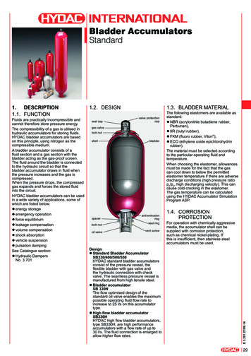
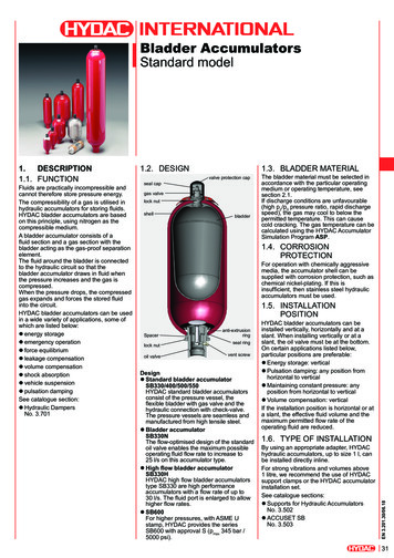
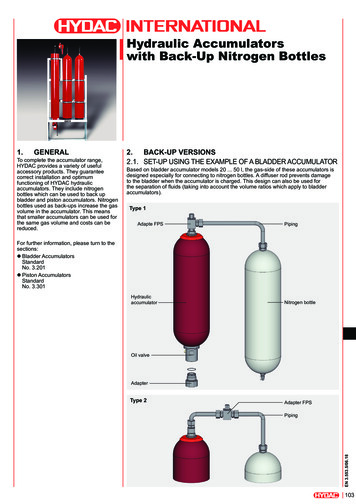
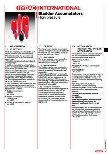
Bladder AccumulatorsHigh pressureFluids are practically incompressible andcannot therefore store pressure energy.The compressibility of a gas (nitrogen)is utilised in hydraulic accumulators forstoring fluids.HYDAC bladder accumulators are basedon this principle.A bladder accumulator consists of a fluidsection and a gas section with the bladderacting as the gas-proof screen.The fluid around the bladder is connectedto the hydraulic circuit so that thebladder accumulator draws in fluid whenthe pressure increases and the gas iscompressed. When the pressure drops,the compressed gas expands and forcesthe stored fluid into the circuit.HYDAC bladder accumulators can be usedin a wide variety of applications and arealso available in different pressure ranges,see catalogue sections:zzBladder AccumulatorsStandardNo. 3.201zzBladder AccumulatorsLow PressureNo. 3.202zzHYDAC Accumulator TechnologyNo. 3.0001.2. DESIGNThe high pressure bladder accumulatorconsists of the pressure vessel, the flexiblebladder with gas valve and the hydraulicconnection with check valve.1.2.1 Shell materialThe forged pressure vessel is seamlessand manufactured from high tensilechrome molybdenum steel.1.2.2 Bladder materialThe bladder material must be selected inaccordance with the particular operatingmedium or operating temperature, seesection 2.2.If discharge conditions are unfavourable(high p2/p0 pressure ratio, rapid dischargespeed), the gas may cool to below thepermitted temperature. This can causecold cracking. The gas temperature can becalculated using the HYDAC AccumulatorSimulation Program ASP.1.2.3 Corrosion protectionFor operation with chemically aggressivemedia, the accumulator shell can bechemically nickel-plated internally orsupplied with a special plastic coating.For external corrosion protection theaccumulator can be supplied with anepoxy resin finish especially for offshoreapplications.1.3. INSTALLATIONPOSITION AND TYPE OFINSTALLATIONInformation on secure installation positionsand mounting elements can be found inthe following catalogue sections:zzBladder AccumulatorsStandardNo. 3.201zzSupports for Hydraulic AccumulatorsNo. 3.502zzACCUSET SBNo. 3.503On no account must any welding, solderingor mechanical work be carried out on theaccumulator shell. After the hydraulic linehas been connected it must be completelyvented.Work on systems with hydraulicaccumulators (repairs, connectingpressure gauges etc.) must only be carriedout once the fluid pressure has beenreleased.The operating instruction must befollowed!No. 3.201.BAWhen replacing seals and/or bladders,please read the Instructions forAssembly and Repair (No. 3.201.M).Note:Application examples, accumulator sizingand extracts from approvals regulationsrelating to hydraulic accumulators can befound in the following catalogue section:zzHYDAC Accumulator TechnologyNo. 3.000E 3.203.6/01.171.DESCRIPTION1.1. FUNCTION37
2.TECHNICAL SPECIFICATIONS2.1. MODEL CODENot all combinations are possible.Order example. For further information, please contact HYDAC.SB690 – 32 A 1 / 312 U – 690 DSeriesNominal volume [l]Fluid portA standard connectionGas-side connection1 standard design 1)9 special design (example.: 1/4" BSP)Material codeFluid connection2 high tensile steel3 stainless steel 2)6 low temperature steelAccumulator shell0 plastic coated (internally)1 carbon steel2 chemically nickel-plated (internal coating)6 low temperature steel8 plastic coated (e.g. Duroplast) internally and externallyAccumulator bladder2 NBR 3)3 ECO4 IIR5 NBR 3)6 FKM7 other9 NBR 3)Certification codeU European Pressure Equipment Directive (PED)Permitted operating pressure [bar]ConnectionA thread to ISO228 (1/2" BSP)D thread to ANSI B1.20.3 (1/2" NPTF)Required gas pre-charge pressure must be stated separately!1)2)E 3.203.6/01.173)38gas valve in SB 10 l 7/8-14UNF,in SB 10 l M50x1.5dependent on type and pressure rangeobserve temperate ranges, see section 2.2.
2.2. EXPLANATORY NOTES2.2.1 Operating pressure690 bar (10000 psi)higher pressures on request2.2.2 Operating temperature and operating fluidThe permitted working temperature of a bladder accumulator is dependent on the application limits of the metal materials and thebladder. Outside this temperature range, special materials must be used. The operating fluid must also be taken into account. Thefollowing table displays a selection of elastomer materials with temperature range and a rough overview of resistant and non-resistantfluids, on a case-by-case basis, information must be requested regarding the resistance and the resistance must be tested specifically:MaterialsMaterialcode 1)Temperature rangeNBR2-15 C . 80 C5-50 C . 50 C9-30 C . 80 CECOEthylene oxide 3epichlorohydrinrubber-30 C . 120 CzzMineral oil (HL, HLP)zzFlame-resistant fluids from theHFB groupzzSynthetic ester (HEES)zzWaterzzSea waterIIRButyl rubber4-50 C . 100 CzzHydraulic fluids of type HFD-RzzFlame-resistant fluids from thegroup HFCzzWaterFKMFluorine rubber 6-10 C . 150 CzzMineral oil (HL, HLP)zzHydraulic fluids of type HFD,zzSynthetic ester (HEES)zzFuelszzAromatic hydrocarbonszzInorganic acids1)2)AcrylonitrilebutadienerubberOverview of the fluids 2)Resistant tozzMineral oil (HL, HLP)zzFlame-resistant fluids from thegroups HFA, HFB, HFCzzSynthetic ester (HEES)zzWaterzzSea waterNot resistant tozzAromatic hydrocarbonszzChlorinated hydrocarbons(HFD-S)zzAmines and ketoneszzHydraulic fluids of type HFD-RzzFuelszzAromatic hydrocarbonszzChlorinated hydrocarbons(HFD-S)zzAmines and ketoneszzHydraulic fluids of type HFD-RzzFlame-resistant fluids from thegroups HFA and HFCzzFuelszzMineral oils and mineral greaseszzSynthetic ester (HEES)zzAliphatic, chlorinated andaromatic hydrocarbonszzFuelszzAmines and ketoneszzAmmoniazzSkydrol and HyJet IVzzSteamsee section 2.1. model code, material code, accumulator bladderothers available on requestE 3.203.6/01.172.2.3 Gas chargingHydraulic accumulators must only be charged with nitrogen.Never use other gases.Risk of explosion!In principle, the accumulator may only be charged with nitrogen class 4.0, filtered to 3 μm.If other gases are to be used, please contact HYDAC for advice.39
3.DIMENSIONS AND SPARE PARTS3.1. DRAWINGS3.1.1 Dimensions3.2. DIMENSIONSMax. operating pressure: 690 bar (PED)Nominalvolume[l]12.5510203254Eff. 114186260Amax.[mm]32453186052286513851900WCSW[mm] [mm]ØD ØEmax.[mm] [mm]61581226745776825011075[mm]3.3. SPARE PARTS3.1.2 Spare parts3.3.1 Part numbersNBRDescriptionBladder assemblyconsisting of:BladderGas valve insertRetaining nutSeal capProtective capO-ringSeal kitconsisting of:O-ringWasherO-ringBleed screwSupport ringRepair kitconsisting of:Seal kit (see above)Bladder assembly (see above)Anti-extrusion ringOil valve assemblyconsisting of:Valve (items 9-13)Anti-extrusion ringWasherO-ringSpacerLock nutBleed screwSupport r shell (item 1) not available as a spare partNominalvolumeSealkit[l]Part airkitPart no.Part 6NOTEAntiextrusionringPart no.2932623028455E 3.203.6/01.17The information in this brochure relates to the operatingconditions and applications described. For applications oroperating conditions not described, please contact the relevanttechnical department. Subject to technical modifications.40HYDAC Technology GmbHIndustriegebiet66280 Sulzbach/Saar; GermanyTel.: 49 (0) 68 97 / 509 - 01Fax: 49 (0) 68 97 / 509 - 464Internet: www.hydac.comE-Mail: speichertechnik@hydac.com
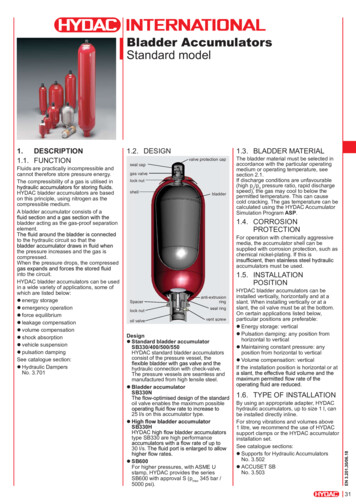
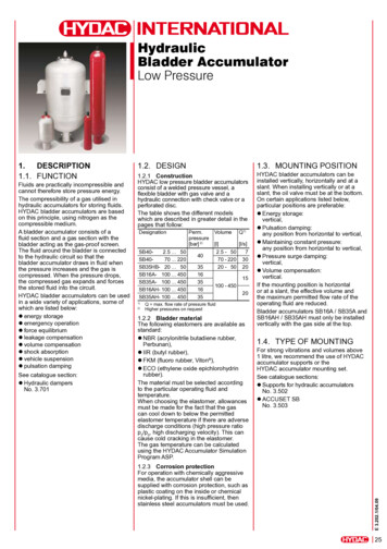
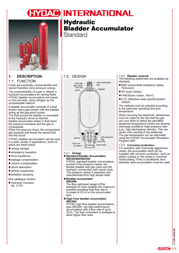
Bladder AccumulatorsLow pressureFluids are practically incompressible andcannot therefore store pressure energy.The compressibility of a gas is utilised inhydraulic accumulators for storing fluids.HYDAC bladder accumulators are basedon this principle, using nitrogen as thecompressible medium.A bladder accumulator consists of afluid section and a gas section with thebladder acting as the gas-proof screen.The fluid around the bladder is connectedto the hydraulic circuit so that thebladder accumulator draws in fluid whenthe pressure increases and the gas iscompressed. When the pressure drops,the compressed gas expands and forcesthe stored fluid into the circuit.HYDAC bladder accumulators can be usedin a wide variety of applications, some ofwhich are listed below:zzEnergy storagezzEmergency operationzzForce equilibriumzzLeakage compensationzzVolume compensationzzShock absorptionzzVehicle suspensionzzPulsation dampingSee catalogue section:zzHydraulic DampersNo. 3.7011.2. DESIGNHYDAC low pressure bladderaccumulators consist of a welded pressurevessel, a flexible bladder with gas valveand a hydraulic connection with checkvalve or a perforated disc.The table shows the different modelswhich are described in greater detail in thepages that follow:DesignationSB402.5 . 50SB4070 . 220SB35HB- 20 . 50SB16A- 100 . 450SB35A- 100 . 450SB16AH- 100 . 450SB35AH- 100 . 4501)2)Perm.pressure[bar] 2)403516351635VolumeQ 1)[l][l/s]2.5 - 50770 - 220 3020 - 50 2015100 - 45020Q max. flow rate of pressure fluidhigher pressures on request1.3. BLADDER MATERIALThe bladder material must be selected inaccordance with the particular operatingfluid or operating temperature, seesection 2.1.If discharge conditions are unfavourable(high p2/p0 pressure ratio, rapid dischargespeed), the gas may cool to below thepermitted temperature.This can cause cold cracking in theelastomer. The gas temperature can becalculated using the HYDAC AccumulatorSimulation Program ASP.1.4. CORROSIONPROTECTIONFor operation with chemically aggressivemedia, the accumulator shell can besupplied with corrosion protection, such asplastic coating on the inside or chemicalnickel-plating. If this is insufficient, thenstainless steel accumulators must be used.1.5. INSTALLATIONPOSITIONHYDAC bladder accumulators can beinstalled vertically, horizontally and at aslant. When installing vertically or at aslant, the oil valve must be at the bottom.On certain applications listed below,particular positions are preferable:zzEnergy storage:vertical,zzPulsation damping:any position from horizontal to vertical,zzMaintaining constant pressure:any position from horizontal to vertical,zzPressure surge damping:vertical,zzVolume compensation:vertical.If the installation position is horizontal orat a slant, the effective fluid volume andthe maximum permitted flow rate of theoperating fluid are reduced.Bladder accumulators SB16A / SB35A andSB16AH / SB35AH must only be installedvertically with the gas side uppermost.1.6. TYPE OF INSTALLATIONFor strong vibrations and volumes above1 litre, we recommend the use of HYDACsupport clamps or the HYDAC accumulatorinstallation set.See catalogue sections:zzSupports for Hydraulic AccumulatorsNo. 3.502zzACCUSET SBNo. 3.503E 3.202.5/01.171.DESCRIPTION1.1. FUNCTION21
2.TECHNICALSPECIFICATIONS2.1. EXPLANATORY NOTES2.1.1 Operating pressuresee section 3. for the particular series(may differ from nominal pressure forforeign test certificates)2.1.2 Nominal volumesee section 3. for the particular series2.1.3 Effective gas volumesee section 3. for the particular seriesBased on nominal dimensions, this differsslightly from the nominal volume and mustbe used when calculating the effective fluidvolume.2.1.4 Effective fluid volumeVolume of fluid which is available betweenthe operating pressures p2 and p1.2.1.5 Max. flow rate of the operatingfluidIn order to achieve the max. flow rate givenin the tables, the accumulator must beinstalled vertically. It must be noted thata residual fluid volume of approx. 10 % ofthe effective gas volume remains in theaccumulator.The maximum fluid flow rate wasdetermined under specific typicalconditions and is not applicable in alloperating conditions.2.1.6 Working temperature and operating fluidThe permitted working temperature of a bladder accumulator is dependent on the application limits of the metal materials and thebladder. Outside this temperature range, special materials must be used. The operating fluid must also be taken into account. Thefollowing table displays a selection of elastomer materials with temperature range and a rough overview of resistant and non-resistantfluids, on a case-by-case basis, information must be requested regarding the resistance and the resistance must be tested specifically:MaterialsMaterialcode 1)Temperature rangeNBR2-15 C . 80 C5-50 C . 50 C9-30 C . 80 CECOEthylene oxide 3epichlorohydrinrubber-30 C . 120 CzzMineral oil (HL, HLP)zzFlame-resistant fluids from theHFB groupzzSynthetic ester (HEES)zzWaterzzSea waterIIRButyl rubber4-50 C . 100 CzzHydraulic fluids of type HFD-RzzFlame-resistant fluids from thegroup HFCzzWaterFKMFluorine rubber 6-10 C . 150 CzzMineral oil (HL, HLP)zzHydraulic fluids of type HFD,zzSynthetic ester (HEES)zzFuelszzAromatic hydrocarbonszzInorganic acids1)E 3.202.5/01.172)22Acrylonitrilebutadienerubbersee section 2.2. Model code, material code, accumulator bladderothers available on requestOverview of the fluids 2)Resistant tozzMineral oil (HL, HLP)zzFlame-resistant fluids from thegroups HFA, HFB, HFCzzSynthetic ester (HEES)zzWaterzzSea waterNot resistant tozzAromatic hydrocarbonszzChlorinated hydrocarbons(HFD-S)zzAmines and ketoneszzHydraulic fluids of type HFD-RzzFuelszzAromatic hydrocarbonszzChlorinated hydrocarbons(HFD-S)zzAmines and ketoneszzHydraulic fluids of type HFD-RzzFlame-resistant fluids from thegroups HFA and HFCzzFuelszzMineral oils and mineral greaseszzSynthetic ester (HEES)zzAliphatic, chlorinated andaromatic hydrocarbonszzFuelszzAmines and ketoneszzAmmoniazzSkydrol and HyJet IVzzSteam
2.1.9 Certificate codesCountryEU member statesAustraliaBelarusCanadaChinaHong KongIcelandJapanKorea (Republic)New ZealandNorwayRussiaSouth AfricaSwitzerlandTurkeyUkraineUSACertificatecode
HYDAC bladder accumulators can be used . in a wide variety of applications and are also available in different pressure ranges, see catalogue sections: z Bladder Accumulators Standard No. 3.201 z Bladder Accumulators Low Pressure accumulator can be supplied with an No. 3.202 z HYDAC Accumulator Technology No. 3.000. 1.2. DESIGN