Transcription
Engineering & Design: Geometric DimensioningSection ContentsNADCA No.FormatPage1 Introduction5-22 What is GD&T?5-23 Why Should GD&T be Used?5-34 Datum Reference Frame5-44.1Primary, Secondary, Tertiary Features & Datums5-44.2Datum Feature Vs. Datum Plane5-54.3Datum Plane Vs. Datum Axis5-54.4Datum Target Sizes & Locations5-65 Feature Control Frame5-66 Rule #1 – Taylor Principle (Envelope Principle)5-77 GD&T Symbols/Meanings5-88 Material Conditions5-88.1Maximum Material Condition (MMC)5-88.2Least Material Condition (LMC)5-98.3Regardless of Feature Size (RFS)5-109 Location Tolerances55-119.1Position Tolerance5-119.2Concentricity & Symmetry Tolerances5-1310 Profile Tolerance5-1411 Run Out Tolerances5-1812 Orientation Tolerances5-1913 Form Tolerances5-2113.1 Straightness5-2113.2 Flatness5-2313.3 Circulatity (Roundness)5-2313.4 Cylindricity5-2314 Conversion Charts5-2914.1 Conversion of Position (Cylindrical) Tolerance Zonesto/from Coordinate Tolerance Zones5-2914.2 Conversion of Position Tolerance Zoneto/from Coordinate Tolerance Zone5-3214.3 Conversion of Coordinate Measurements toPosition Location Measurements5-33NADCA Product Specification Standards for Die Castings / 2006SECTION55-1
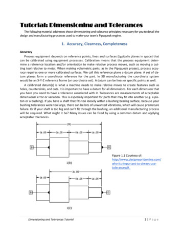
Engineering & Design: Geometric Dimensioning1IntroductionThe concept of Geometric Dimensioning and Tolerancing (GD&T) was introduced by StanleyParker from Scotland in the late 1930’s. However it was not used to any degree until World WarII (WW II) because until then the vast majority of products were made in-house. The designercould discuss with the manufacturing personnel (die designer, foundry foreman, machinist,and inspectors) what features were to be contacted to establish the so called “centerlines” thatwere used on the drawing to locate features such as holes and keyways. Also when two (2) ormore features were shown coaxial or symmetrical around these “centerlines”, the questions thatneeded to be answered by the designer was, “how concentric or symmetrical do these featureshave to be to each other”?. During WW II companies had to “farm out” parts because of thequantities/schedules. This meant the new manufacturer had to interpret the drawing hence the“centerlines” were often established by contacting features that were not functional or importantand features produced from these incorrect “centerlines” were not at the location required. Theparts did not assemble and/or did not function properly hence had to be fi xed or scrapped. GD&Twas the solution to this major problem. GD&T provides a designer the tools to have clear, concise,and consistent instructions as to what is required. It eliminates ambiguities hence everyone that isinvolved with the part will not have to interpret the dimensioning.2What is GD&T?It is compilation of symbols and rules that efficiently describe and control dimensioning &tolerancing for all drawings (castings, machined components,etc.). It is documented in ASMEY14.5M which has the symbols, rules, and simple examples. Also ASME Y14.8 has guidance forcasting and forging drawings.3Why should GD&T be used?a. It is a simple and efficient method for describing the tolerancing mandated by the designer ofthe part.b. It eliminates ambiguities as to what Datum features are to be contacted to establish the Datumplanes and/or Datum axis that are to be used for locating other features. All inspection willresult in the same result – the dimension is within or out of tolerance. Fig. 5-1 illustrates asimple example of ambiguities associated with the “old” type drawing. Fig. 5-2 illustrates thesame example with GD&T.c. It simplifies inspection because hard gages can often be utilized and inspection fi xtures areoften mandated which simplifies inspection for production quantities.d. It forces the designer to totally consider function, manufacturing process, and inspectionmethods. The result is larger tolerances that guarantee function, but reduce manufacturing& inspection costs. Also the “bonus” or extra tolerance for certain conditions can result insignificant production cost savings. In addition the time to analyze whether a missed dimension is acceptable is dramatically reduced.5-2NADCA Product Specification Standards for Die Castings / 2006
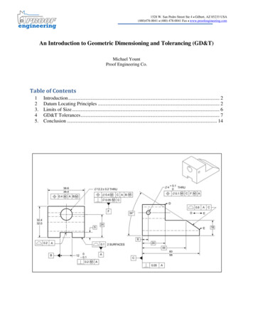
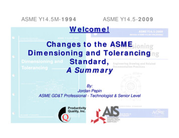
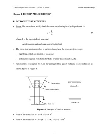
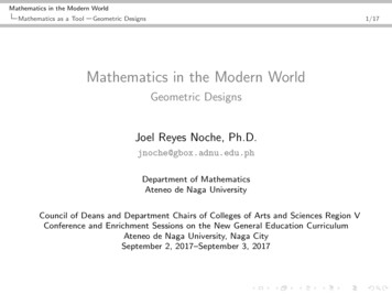
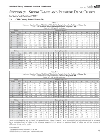
Engineering & Design: Geometric DimensioningFig. 5-1 “OLD” Drawing without GD&T.Questions:1) What is the relationship (coaxiality tolerance) between the 1.00 and the 2.00?2) Which feature ( 1.00 or 2.00) is to be used for measuring (locating) the .500 .005 dimensionfor locating the .120 hole?5Fig. 5-2 “NEW” Drawing with GD&T.Questions asked in Fig. 5-1 answered:1) The axis of the 2.00 has to be coaxial with the axis of the 1.00 within a tolerance zone thatis a .005 if the is 2.01 which is the MMC.2) The 1.00 is the feature to be used for measuring the .500 dimension for locating the n.120hole. The tolerance for locating the .120 hole is a of .014 (the diagonal of the rectangulartolerance zone shown in Fig. 5-1) when the hole is a MMC ( .120).NADCA Product Specification Standards for Die Castings / 20065-3
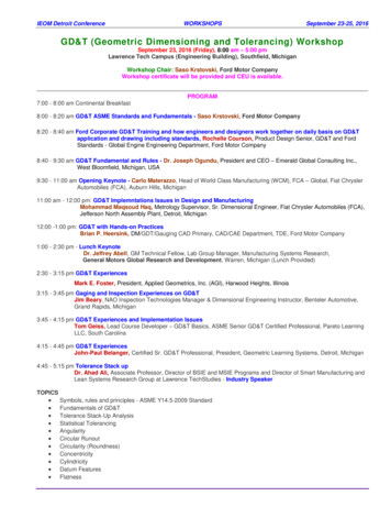
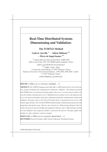
Engineering & Design: Geometric Dimensioning4Datum Reference Frame (DRF):The DRF is probably the most important concept of GD&T. In order to manufacture and/orinspect a part to a drawing , the three (3) plane concept is necessary. Three (3) mutuallyperpendicular (exactly 90 to each other) and perfect planes need to be created to measurefrom. In GD&T this is called Datum Reference Frame whereas in mathematics it is the Cartesiancoordinate system invented by Rene Descartes in France (1596-1650). Often one would expressthis concept as the need to establish the X,Y, and Z coordinates. The DRF is created by so-calledDatum Simulators which are the manufacturing, processing, and inspection equipment such assurface plate, a collet, a three jaw chuck, a gage pin, etc. The DRF simulators provide the originof dimensional relationships. They contact the features (named Datum Features) which of courseare not perfect hence measurements from simulators (which are nearly perfect) provides accuratevalues and they stabilize the part so that when the manufacturer inspects the part and thecustomer inspects the part they both get the same answer. Also if the part is contacted during theinitial manufacturing setup in the same manner as when it is inspected, a “layout” for assuringmachining stock is not required. The final result (assuming the processing equipment is suitablefor the tolerancing specified) will be positive.4.1 Primary, Secondary, and Tertiary Features & Datums:The primary is the first feature contacted (minimum contact at 3 points), the secondary feature isthe second feature contacted (minimum contact at 2 points), and the tertiary is the third featurecontacted (minimum contact at 1 point). Contacting the three (3) datum features simultaneouslyestablishes the three (3) mutually perpendicular datum planes or the datum reference frame. Ifthe part has a circular feature that is identified as the primary datum feature then as discussedlater a datum axis is obtained which allows two (2) mutually perpendicular planes to intersect theaxis which will be the primary and secondary datum planes. Another feature is needed (tertiary)to be contacted in order orientate (fi x the two planes that intersect the datum axis) and to establish the datum reference frame. Datum features have to be specified in an order of precedenceto properly position a part on the Datum Reference Frame. The desired order of precedence isobtained by entering the appropriate datum feature letter from left to right in the Feature ControlFrame (FCF) (see Section 5 for explanation for FCF). The first letter is the primary datum, thesecond letter is the secondary datum, and the third letter is the tertiary datum. The letter identifies the datum feature that is to be contacted however the letter in the FCF is the datum plane oraxis of the datum simulators. See Fig. 5-3 for Datum Features & Planes.Fig. 5-3 Primary, secondary, tertiary features & datum planes.5-4NADCA Product Specification Standards for Die Castings / 2006
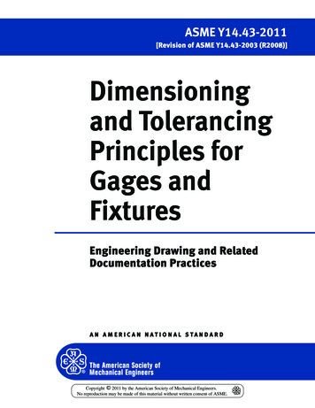
Engineering & Design: Geometric Dimensioning4.2 Datum Feature vs Datum Plane:The datum features are the features (surfaces) on the part that will be contacted by the datumsimulators. The symbol is a capital letter (except I,O, and Q) in a box such as A used in the 1994ASME Y14.5 or -A- used on drawings made to the Y14.5 before 1994. The features are selectedfor datums based on their relationship to toleranced features, i.e., function, however they must beaccessible, discernible, and of sufficient size to be useful. A datum plane is a datum simulator suchas a surface plate. See Fig. 5-4 for a Datum Feature vs a Datum Plane.Fig. 5-4 Datum feature vs. datum plane.4.3 Datum Plane vs Datum Axis:A datum plane is the datum simulator such as a surface plate. A datum axis is also the axis ofa datum simulator such as a three (3) jaw chuck or an expandable collet (adjustable gage). It isimportant to note that two (2) mutually perpendicular planes can intersect a datum axis howeverthere are an infinite number of planes that can intersect this axis (straight line). Only one (1) setof mutually perpendicular planes have to be established in order to stabilize the part (everyonehas to get the same answer – does the part meet the drawing requirements?) therefore a featurethat will orientate or “clock” or “stabilize” has to be contacted. The datum planes and datum axisestablish the datum reference frame and are where measurements are made from. See Fig. 5-5 forDatum Feature vs Datum Axis.5Fig. 5-5 Datum feature vs. datum axis.NADCA Product Specification Standards for Die Castings / 20065-5
Engineering & Design: Geometric Dimensioning4.4 Datum Target Sizes & Locations:Datum targets are datum simulators such as spherical pins or round flat bottom pins or three (3)jaw chucks or centers that establish datum planes or datum axis. They contact the datum featuresand are often specified to be used for inspecting parts that are inherently not round or straightor flat or they are large parts. If targets are not used then the entire datum feature has to contacta datum simulator. An example of what can result is the part could “rock” on a surface plate ifthe part was not relatively flat which would result in an unstable scenario and conflicting results.If the datum feature is large a datum simulator that contacts the entire feature may not exist orwould be extremely expensive to produce. The datum targets are the datum planes and datumaxis and often are assembled together to create an inspection fi xture and or a manufacturingfi xture. See Fig. 5-6 for Datum Target Sizes & Locations.Component configuration shown as phantom lines on seperate drawing Illustrates orientation when targets contact component Illustrates that targets are physically seperate from the component Apply marking is shown to depict which side is to be contacted by the targetsFig. 5-6 Target sizes & locations.5Feature Control Frame:The geometric tolerance for an individual feature is specified in the Feature Control Frame whichis divided into compartments – see Fig 5-7. The first compartment contains the type of geometriccharacteristic such as true position, profile, orientation, etc. The second compartment containsthe tolerance (where applicable the tolerance is preceded by a diameter symbol and followed by amaterial condition symbol). The remaining compartments contain the datum planes or axis in theproper sequence (primary datum is the first letter).Fig. 5-7 Feature control frame.5-6NADCA Product Specification Standards for Die Castings / 2006
Engineering & Design: Geometric Dimensioning6Rule # 1 – Taylor Principle (Envelope Principle):When only a size tolerance is specified for an individual feature of size the form of this featureshall not extend beyond a boundary (envelope) of perfect form at maximum material condition(MMC). In other words when the size is at MMC the feature has to be perfectly straight. If theactual size is less than the MMC the variation in form allowed is equal to the difference betweenthe MMC and the actual size. The relationship between individual features is not controlledby size limits. Features shown perpendicular, coaxial or symmetrical to each other must becontrolled for location or orientation otherwise the drawing is incomplete. In other words Fig. 5-1is an incomplete drawing. Fig. 5-8 shows the meaning of Rule #1 for an external cylinder (pin orshaft) and an internal cylinder (hole). Note that a hard gage can be used to inspect this principleor requirement.5Fig. 5-8 Rule #1.NADCA Product Specification Standards for Die Castings / 20065-7
Engineering & Design: Geometric Dimensioning7ToleranceTypeFormLocationGD&T Symbols / MeaningsGeometric Characteristics Flatness Circularity{Cylindricity Positional Tolerance { Feature ofSize Dim.DatumUse L or Gages UsedReference M SYES***NONO{{ ——————— NOYESYESParallelism YESYESYESYESYES***Angularity Profile of a Surface Profile of a Line YESNOYES*YES**NOYESYESYESNONOSymmetryOrientation PerpendicularityRunoutApplied mbolCircular RunoutTotal Runout* Can be used to control form without a datum reference.** Datum reference only.*** – Yes if M is specified for the feature of size being controlled– No if S or L are specified for the feature of size being controlled.8Material Conditions:Features of size which includes datum features have size tolerances hence the size condition ormaterial (amount of metal) condition can vary from the maximum metal condition (MMC) to theleast metal condition (LMC). Consequently if the center planes or axes of a feature of size arecontrolled by geometric tolerances a modifying symbol can be specified in the feature controlframe that applies the tolerance value at either the maximum or the least material condition. Italso can be specified for a datum that is a feature of size. If a symbol is not
Fig. 5-2 “NEW” Drawing with GD&T. Questions: 1) What is the relationship (coaxiality tolerance) between the 1.00 and the 2.00? 2) Which feature ( 1.00 or 2.00) is to be used for measuring (locating) the .500 .005 dimension for locating the .120 hole? Questions asked in Fig. 5-1 answered: 1) The axis of the 2.00 has to be coaxial with the axis of the 1.00 within a .