Transcription
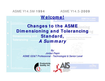
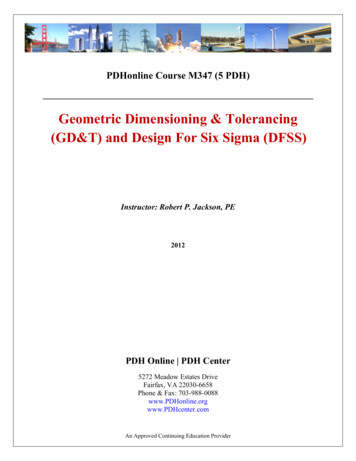
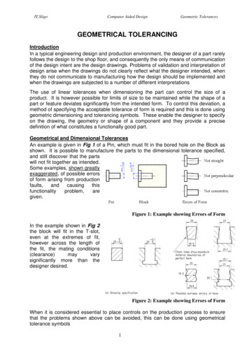
IT,SligoComputer Aided DesignGeometric TolerancesGEOMETRICAL TOLERANCINGIntroductionIn a typical engineering design and production environment, the designer of a part rarelyfollows the design to the shop floor, and consequently the only means of communicationof the design intent are the design drawings. Problems of validation and interpretation ofdesign arise when the drawings do not clearly reflect what the designer intended, whenthey do not communicate to manufacturing how the design should be implemented andwhen the drawings are subjected to a number of different interpretationsThe use of linear tolerances when dimensioning the part can control the size of aproduct. It is however possible for limits of size to be maintained while the shape of apart or feature deviates significantly from the intended form. To control this deviation, amethod of specifying the acceptable tolerance of form is required and this is done usinggeometric dimensioning and tolerancing symbols. These enable the designer to specifyon the drawing, the geometry or shape of a component and they provide a precisedefinition of what constitutes a functionally good part.Geometrical and Dimensional TolerancesAn example is given in Fig 1 of a Pin, which must fit in the bored hole on the Block asshown. It is possible to manufacture the parts to the dimensional tolerance specified,and still discover that the partswill not fit together as intended.Some examples, shown greatlyexaggerated, of possible errorsof form arising from m,aregiven.Figure 1: Example showing Errors of FormIn the example shown in Fig 2the block will fit in the T-slot,even at the extremes of fit,however across the length ofthe fit, the mating conditions(clearance)mayvarysignificantly more than thedesigner desired.Figure 2: Example showing Errors of FormWhen it is considered essential to place controls on the production process to ensurethat the problems shown above can be avoided, this can be done using geometricaltolerance symbols1
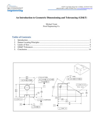
IT,SligoComputer Aided DesignGeometric TolerancesWhen Geometrical Tolerances are UsedGeometrical tolerances should be specified for all requirements critical to functioningand interchangeability, except when it is known that the machinery and manufacturingtechniques that will be used can be relied on to achieve the required standard ofaccuracy. Geometrical tolerances should be specified only where they are essential,otherwise the manufacturing and inspection costs may be increased. In any case tolerances should be as large as possible, subject to the design requirements being met. Asgeometrical tolerancing symbols are internationally agreed (see ISO 1101), languagedifficulties cannot occur. The use of geometrical tolerances does not imply that anyparticular method of production or inspection is to be used.Features of a ComponentFig 3 illustrates some of the single features that may be present on a component. Geometrical tolerances may be applied to these features. For example, an axis may have astraightness or a positional tolerance, a face may have a flatness tolerance and acylindrical surface may have a circularity tolerance.The single features in Fig 3 may becombined to form other features such asslots, grooves and tongues. Thus, a tongueconsists of a pair of parallel plane surfaceswith another plane surface at right angles tothem, and a median plane. Slots, groovesand tongues may need tolerances of positionor symmetry.Figure 3: Feature of a ComponentTolerance Frame:Geometrical tolerances are placed in rectangular frames that are divided intocompartments as shown in Fig 4. In the first compartment from the left the symbol forthe characteristic being toleranced is given. The next compartment contains the tolerance value inthe units used for linear dimensions. If the tolerancezone is circular or cylindrical the symbol Ø appearsbefore the tolerance value. The third and succeeding compartments contain theletters which identify the datum feature or features,where appropriate.Figure 4 Tolerance Frame The capitol letter “M”, “P” or “E” may appear in the tolerance frame as appropriate, toindicate Maximum Material Condition qualification Projected Tolerance Zone Envelope Requirement.2
IT,SligoComputer Aided DesignGeometric TolerancesTolerance Characteristic Symbol:The straightness of an axis, the flatness of a face, etc, are characteristics of featuresand these are indicated on drawings using the symbols shown in Fig 5.Figure 5: Tolerance Characteristic SymbolSingle and Related Features:As the tolerances of Form, indicated in the table above, relate to single features, adatum feature is not required (e.g. the flatness of a face does not require reference toany other feature of the part).The Related Feature tolerances necessitate the identification and specification of anappropriate datum (i.e. if a face must be parallel, then you must indicate what feature itmust be parallel to – and that feature is referred to as the datum).Datums:Datums are used to establish the relationship of geometricallytoleranced features and a datum is a theoretically exactgeometrical reference, such as an axis, plane, straight line,etc. The datum is indicated by an equilateral triangle symbolas shown in Fig 6 and is usually identified by a capitol letterenclosed in a frame, with different letters used to identify eachdatum. Figure 6: DatumsWhen the base of the triangle lies on the outline or extension of the outline of afeature, the datum feature is the line or surface itself.When the datum triangle is an extension of a diameter dimension line, or on anaxis line, the datum is the axis.When the datum triangle is an extension of a width dimension line, or on amedian plane line, the datum is the median plane.3
IT,SligoComputer Aided DesignGeometric TolerancesAdditional Symbols:The symbols in Fig 7 identifyand qualify toleranced features,datums and dimensions.Figure 7: Symbols that Identify, Qualify and Indicate1 Theoretically Exact Dimensions:When tolerances of position, profile or angularity arespecified for a feature, the ideal position or angle isdefined by theoretically exact dimension.Thesedimensions are enclosed in a rectangular frame, called abox as shown using the example opposite.2 Projected Tolerance Zone:When indicating the positional tolerance zone for the axis of ahole, the perpendicularity deviations of the axis may bespecified also. If the hole is to be used to secure a cylindricalpart such as a press-fit pin, the maximum permittedperpendicularity deviation of the hole axis could cause the pinto interfere with the clearance hole in the mating part. This maybe avoided by specifying a projected tolerance zone for theaxis of the securing hole, as shown opposite.3 Datum Targets:If a feature is large, geometrical imperfections may make itimpracticable to use its entire surface to establish a datum. Toestablish practical datums, suitable locations on the part, calleddatum targets, may be selected and indicated on the drawing.4 Envelope Requirement:This requirement means that the envelope of perfect form atthe maximum material size is not to be violated. Used inspecial circumstances to ensure that mating features willalways assemble.4
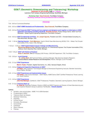
IT,SligoComputer Aided DesignGeometric Tolerances5 Maximum Material Principle:This principle requires the specified geometrical tolerance to be applied rigorously onlywhen the feature is in its maximum material condition (MMC). When the feature isfinished away from its maximum material limit of size the geometrical tolerance ispermitted to increase by the difference between the maximum material limit and theactual finished size of the feature. Obviously the difference cannot exceed the sizetolerance specified for the feature and the surface of the feature cannot cross thesurface of the virtual condition (envelope).Symbols used on DrawingsA number of geometric tolerances havebeen applied to the Gearbox body shownopposite in Fig 8.Figure 8: Gearbox BodySymbols in SolidWorksGeometric tolerances and Datums canbe inserted into drawings in SolidWorksusing the tools shown opposite(Annotations toolbar).The required geometric tolerancesymbols can be selected and entered inthe appropriate edit boxes found in theProperties dialogue box, as shownopposite.ISO 1101 – Extract from InternationalStandardsOn the following page is a single pageextract from ISO 1101 (GeometricalTolerancing), suitable for everyday use.5
IT,SligoComputer Aided Design6Geometric Tolerances
geometrical tolerancing symbols are internationally agreed (see ISO 1101), language difficulties cannot occur. The use of geometrical tolerances does not imply that any particular method of production or inspection is to be used. Features of a Component Fig 3 illustrates some of the single features that may be present on a component. Geo-