Transcription
CATIA Kinematics3DEXPERIENCE R2019xTABLE OF CONTENTSIntroduction . . . . . . . . . . . . . . . . . . . . . . . . . . . . . . . . . . . . . . . . . . . . . . . . . . . . . . . . . . . . . . 1Kinematics . . . . . . . . . . . . . . . . . . . . . . . . . . . . . . . . . . . . . . . . . . . . . . . . . . . . . . . . . 2Mechanical Systems Design Workbench . . . . . . . . . . . . . . . . . . . . . . . . . . . . . . . . . . 3Mechanical Systems Experience Workbench . . . . . . . . . . . . . . . . . . . . . . . . . . . . . 12Saving Requirements . . . . . . . . . . . . . . . . . . . . . . . . . . . . . . . . . . . . . . . . . . . . . . . . 15Kinematics . . . . . . . . . . . . . . . . . . . . . . . . . . . . . . . . . . . . . . . . . . . . . . . . . . . . . . . . . . . . . . 17Engineering Connection Types . . . . . . . . . . . . . . . . . . . . . . . . . . . . . . . . . . . . . . . . 17Revolute - Null Offset . . . . . . . . . . . . . . . . . . . . . . . . . . . . . . . . . . . . . . . . . 18Mechanism Representation . . . . . . . . . . . . . . . . . . . . . . . . . . . . . . . . . . . . . 21Mechanism Manager . . . . . . . . . . . . . . . . . . . . . . . . . . . . . . . . . . . . . . . . . . 23Prismatic . . . . . . . . . . . . . . . . . . . . . . . . . . . . . . . . . . . . . . . . . . . . . . . . . . . 30Cylindrical - Angle and Length . . . . . . . . . . . . . . . . . . . . . . . . . . . . . . . . . . 36Cylindrical - Length . . . . . . . . . . . . . . . . . . . . . . . . . . . . . . . . . . . . . . . . . . . 42Cylindrical - Angle . . . . . . . . . . . . . . . . . . . . . . . . . . . . . . . . . . . . . . . . . . . 47Screw . . . . . . . . . . . . . . . . . . . . . . . . . . . . . . . . . . . . . . . . . . . . . . . . . . . . . . 51Spherical . . . . . . . . . . . . . . . . . . . . . . . . . . . . . . . . . . . . . . . . . . . . . . . . . . . 57Planar . . . . . . . . . . . . . . . . . . . . . . . . . . . . . . . . . . . . . . . . . . . . . . . . . . . . . . 61Rigid . . . . . . . . . . . . . . . . . . . . . . . . . . . . . . . . . . . . . . . . . . . . . . . . . . . . . . . 65Point Curve . . . . . . . . . . . . . . . . . . . . . . . . . . . . . . . . . . . . . . . . . . . . . . . . . 68Slide Curve . . . . . . . . . . . . . . . . . . . . . . . . . . . . . . . . . . . . . . . . . . . . . . . . . 71Roll Curve . . . . . . . . . . . . . . . . . . . . . . . . . . . . . . . . . . . . . . . . . . . . . . . . . . 74Point Surface . . . . . . . . . . . . . . . . . . . . . . . . . . . . . . . . . . . . . . . . . . . . . . . . 77Universal . . . . . . . . . . . . . . . . . . . . . . . . . . . . . . . . . . . . . . . . . . . . . . . . . . . 80Gear . . . . . . . . . . . . . . . . . . . . . . . . . . . . . . . . . . . . . . . . . . . . . . . . . . . . . . . 85Rack . . . . . . . . . . . . . . . . . . . . . . . . . . . . . . . . . . . . . . . . . . . . . . . . . . . . . . . 91Cable . . . . . . . . . . . . . . . . . . . . . . . . . . . . . . . . . . . . . . . . . . . . . . . . . . . . . . 94Mechanism Operations . . . . . . . . . . . . . . . . . . . . . . . . . . . . . . . . . . . . . . . . . . . . . . 97Dressup . . . . . . . . . . . . . . . . . . . . . . . . . . . . . . . . . . . . . . . . . . . . . . . . . . . . 97Joint Limits . . . . . . . . . . . . . . . . . . . . . . . . . . . . . . . . . . . . . . . . . . . . . . . . 102Assembly Mechanisms . . . . . . . . . . . . . . . . . . . . . . . . . . . . . . . . . . . . . . . 107Kinematic Simulations . . . . . . . . . . . . . . . . . . . . . . . . . . . . . . . . . . . . . . . . . . . . . . 113Creating a Kinematic Simulation . . . . . . . . . . . . . . . . . . . . . . . . . . . . . . . . 113Kinematic Scenarios . . . . . . . . . . . . . . . . . . . . . . . . . . . . . . . . . . . . . . . . . 116Recording a Scenario . . . . . . . . . . . . . . . . . . . . . . . . . . . . . . . . . . . . . . . . . 118Editing a Recorded Scenario . . . . . . . . . . . . . . . . . . . . . . . . . . . . . . . . . . . 122Creating a Scenario with a Law . . . . . . . . . . . . . . . . . . . . . . . . . . . . . . . . . 125Creating a Scenario with a Design Table . . . . . . . . . . . . . . . . . . . . . . . . . . 132Creating a Segmented Excitation . . . . . . . . . . . . . . . . . . . . . . . . . . . . . . . . 144Plotting Excitations . . . . . . . . . . . . . . . . . . . . . . . . . . . . . . . . . . . . . . . . . . 152Assembly Sequences . . . . . . . . . . . . . . . . . . . . . . . . . . . . . . . . . . . . . . . . . 154 Wichita State UniversityTable of Contents, Page i
CATIA Kinematics3DEXPERIENCE R2019xDynamic Scenarios . . . . . . . . . . . . . . . . . . . . . . . . . . . . . . . . . . . . . . . . . . 165Gravity Excitation . . . . . . . . . . . . . . . . . . . . . . . . . . . . . . . . . . . . . 173Position Motor Excitation . . . . . . . . . . . . . . . . . . . . . . . . . . . . . . . 174Velocity Law Excitation . . . . . . . . . . . . . . . . . . . . . . . . . . . . . . . . 176Velocity Motor Excitation . . . . . . . . . . . . . . . . . . . . . . . . . . . . . . . 178Sketched Law Excitations . . . . . . . . . . . . . . . . . . . . . . . . . . . . . . . . . . . . . 183Probes . . . . . . . . . . . . . . . . . . . . . . . . . . . . . . . . . . . . . . . . . . . . . . . . . . . . . 190Measure Probe . . . . . . . . . . . . . . . . . . . . . . . . . . . . . . . . . . . . . . . . 190Interference Probe . . . . . . . . . . . . . . . . . . . . . . . . . . . . . . . . . . . . . 195Results . . . . . . . . . . . . . . . . . . . . . . . . . . . . . . . . . . . . . . . . . . . . . . . . . . . . . . . . . . 203Preview Scenario . . . . . . . . . . . . . . . . . . . . . . . . . . . . . . . . . . . . . . . . . . . . 203Compute and Generate Results with Local Update . . . . . . . . . . . . . . . . . . 204Compute and Generate Results with Global Update . . . . . . . . . . . . . . . . . 208View Scenario Results . . . . . . . . . . . . . . . . . . . . . . . . . . . . . . . . . . . . . . . . 211Geometric Trace . . . . . . . . . . . . . . . . . . . . . . . . . . . . . . . . . . . . . . . . . . . . . 216Swept Volume . . . . . . . . . . . . . . . . . . . . . . . . . . . . . . . . . . . . . . . . . . . . . . 222Exporting an Animation . . . . . . . . . . . . . . . . . . . . . . . . . . . . . . . . . . . . . . . 227Snapshots . . . . . . . . . . . . . . . . . . . . . . . . . . . . . . . . . . . . . . . . . . . . . . . . . . 228Play Animation . . . . . . . . . . . . . . . . . . . . . . . . . . . . . . . . . . . . . . . . . . . . . 230Problems . . . . . . . . . . . . . . . . . . . . . . . . . . . . . . . . . . . . . . . . . . . . . . . . . . . . . . . . . . . . . . 231Problem #1 . . . . . . . . . . . . . . . . . . . . . . . . . . . . . . . . . . . . . . . . . . . . . . . . . . . . . . . 231Problem #2 . . . . . . . . . . . . . . . . . . . . . . . . . . . . . . . . . . . . . . . . . . . . . . . . . . . . . . . 232Problem #3 . . . . . . . . . . . . . . . . . . . . . . . . . . . . . . . . . . . . . . . . . . . . . . . . . . . . . . . 233Problem #4 . . . . . . . . . . . . . . . . . . . . . . . . . . . . . . . . . . . . . . . . . . . . . . . . . . . . . . . 234Problem #5 . . . . . . . . . . . . . . . . . . . . . . . . . . . . . . . . . . . . . . . . . . . . . . . . . . . . . . . 235Table of Contents, Page ii Wichita State University
CATIA Kinematics3DEXPERIENCE R2019xIntroductionCATIA Version 6 KinematicsUpon completion of this course the student should have a full understanding of thefollowing topics:-Creating joints-Creating simulations and replays-Performing analysis on a kinematic mechanism-Using laws to help simulate a mechanism-Converting assembly constraints to joints Wichita State UniversityKinematics - Introduction, Page 1
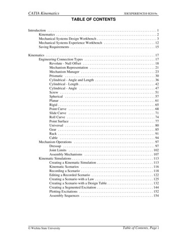
CATIA Kinematics3DEXPERIENCE R2019xKinematicsThe first item that needs to be understood is the definition of kinematics. Kinematicsinvolves an assembly of parts that are connected together by a series of joints, referred to asa mechanism. These joints define how an assembly can perform motion. When one of thejoints move it causes the assembly to move. Kinematics does not involve any type of finiteelement analysis, which means that there are no associated loads or weights with the parts.You are simply moving the assembly through some range of motion as defined by thejoints.Sometimes kinematics gets confused with animation as well. Although kinematics doesperform some actions similar to animation, it is very limited. Kinematics is meant to showthe range of motion of a mechanical component. Basically, it will show how the movementof one joint affects all of the other joints defined in the mechanism.The second concept that needs to be understood are degrees of freedom. Every part has sixdegrees of freedom. It can move in three directions, and it can also rotate about those threedirections. In order for an assembly to be used in kinematics, it must have at least onedegree of freedom. The remaining degrees of freedom are controlled with commands. Thisis what allows the motion of the mechanism to be defined.The hardest part about kinematics is figuring out what joints need to be defined on anassembly in order for it to operate correctly. The actual definition of the joints is prettyeasy. Kinematics requires you to think a little differently without allowing finite elementanalysis and animation confuse the situation.Kinematics is used to check for clearances and interferences among moving parts, andanalyze the velocities of parts as well. In addition, laws can be applied to the mechanism toforce the parts to accelerate.There are two main kinematic apps: Mechanical Systems Design and Mechanical SystemsExperience. Mechanical Systems Design is primarily used to define all the joints in thekinematic mechanism. It will be the focus of the first half of this manual. MechanicalSystems Experience is primarily used after the kinematic mechanism has been defined.This app is primarily used to simulate the mechanism. It will be the focus of the secondhalf of this manual.Kinematics - Introduction, Page 2 Wichita State University
CATIA Kinematics3DEXPERIENCE R2019xKinematicsEngineering Connection TypesThere are many engineering connection types. Each type has degrees of freedom andcommands associated with it. A good understanding of these will make performingkinematics much easier. The table below gives an overview of the engineering connections.Some of the connections can be created using axis systems but that will be discussed later.Engineering ConnectionDegrees of FreedomCommands ical3 RotationsNoneCylindrical1 Rotation, 1 TranslationAngle and/or LengthPlanar1 Rotation, 2 TranslationsNonePrismatic1 TranslationLengthRevolute1 RotationAngleScrew1 Rotation or 1 TranslationAngle or LengthPoint Curve3 Rotations, 1 TranslationLengthPoint Surface3 Rotations, 2 TranslationsNoneGear1 RotationAngleRack1 Rotation or 1 TranslationAngle or LengthCable1 TranslationLengthUniversal1 RotationNoneRoll Curve1 Rotation, 1 TranslationLengthSlide Curve2 Rotations, 1 TranslationNoneFixNoneNone Wichita State UniversityKinematics - Joints, Page 17
CATIA Kinematics3DEXPERIENCE R2019xRevolute - Null OffsetThe revolute option allows you to define a joint that represents a rotation. This is usefulwhen you need an object to turn about another object.Open the KINE110 - Revolute Assembly document. You should see a base with threerings.If not already there, switch to the Mechanical System Design app.Select the Engineering Connection icon.The Engineering Connection Definitionwindow appears. This window should be familiar from the Assembly Design workbench.Select the Gyroscope Base from the tree. Notice the Type automatically switches to Fix.You must always have a fixed object in order to create a kinematic simulation.Select OK. The engineering connection is created.Kinematics - Joints, Page 18 Wichita State University
CATIA KinematicsSelect the Engineering Connection icon.window appears.3DEXPERIENCE R2019xThe Engineering Connection DefinitionSelect the center line of the cylinder on the outside ring and the center line of thecutout on the base as shown below. This defines the center of rotation and aligns the twolines.Select the zx plane in both parts. This defines the location of each object by aligning thetwo planes. You will probably have to expand the branches of the Base and 1st Ring inorder to select the planes. Notice the Type automatically updates to Revolute.The command will need to control the angle of the Cam in relation to the Fixture1 part, soyou will need to create an Angle constraint to apply the command to. Wichita State UniversityKinematics - Joints, Page 19
CATIA Kinematics3DEXPERIENCE R2019xRight select on the Select an element text in the window and select Insert, Angle, Angle.An angle constraint is inserted.Select the xy plane in both parts. This will be the reference for the rotation angle. Thewindow should appear as shown.Notice the Type has an error symbol next to it. The Mode of the angle constraint needs tobe switched to Controlled.Right select on the symbol under the Mode column as shown above and selectControlled. The error symbol goes away.Select OK. The engineering connection is created.Kinematics - Joints, Page 20 Wichita State University
CATIA Kinematics3DEXPERIENCE R2019xMechanism RepresentationThe mechanism representation will contain all of the kinematic information for simulatingmovement within your assembly. It is a separate representation, similar to a 3d shaperepresentation, that will be stored within the assembly.Select the Mechanism Representation icon.window appears.The Mechanism RepresentationChange the Title to KINE110 - Kinematic Mechanism.Select the Mechanism Options tab.Include all kinematics connections.Creates joints from all of the existingengineering connections in the modelCreate all possible kinematic commandsCreates commands from any existingcontrolled c
CATIA Kinematics 3DEXPERIENCE R2019x Kinematics The first item that needs to be understood is the definition of kinematics. Kinematics involves an assembly of parts that are connected together by a series of joints, referred to as a mechanism. These joints