Transcription
Real-Time Distributed SystemsDimensioning and Validation:The TURTLE MethodLudovic Apvrille * — Ahlem Mifdaoui **— Pierre de Saqui-Sannes *** Institut Telecom, Telecom ParisTech, CNRS LTCI2229 rte des Crêtes, B.P. 193, 06904 Sophia-Antipolis, Franceludovic.apvrille@telecom-paristech.fr** CNRS ; LAAS ; ISAE7 avenue du colonel Roche, F-31077 Toulouse, FranceToulouse University; Université de Toulouse ; UPS, INSA, INP, ISAE ; LAAS ;F-31077 Toulouse, France{Ahlem.Mifdaoui, pdss}@isae.frRÉSUMÉ. A dŐfinir par la commande \resume{.}ABSTRACT. The TURTLE language and toolkit offer a UML framework for service description, protocol modeling and communication architecture validation. The method associatedwith TURTLE uses an architectural design pattern where two or several protocol entities relyon a pre-existing communication service. Modeling the pre-existing service with empirical values is error-prone and hampers large space exploration during the communication architecturevalidation. The paper relies on the Network Calculus theory to parameterizes the service withrealistic upper bounds. The revisited TURTLE method includes a dimensioning step between therequirement and analysis steps. This new step is based on a "Dimensioning Diagram" that describes the network in terms of traffic and equipments behavior, and a "Dimensioning-orientedUse Case Diagram" that categorizes the flows conveyed by the network. The paper applies thismethod to a video conference system as example.MOTS-CLÉS : A dŐfinir par la commande \mots les{.}KEYWORDS: Network Calculus, UML, Formal Verification, Distributed Systems.Studia Informatica Universalis.
2Studia Informatica Universalis.1. IntroductionThe term real-time UML profile denotes the family of modelinglanguages that customizes the Unified Modeling Language [Gro03]for real-time applications and platforms. TURTLE [ALCdSS04] is areal-time UML profile supported by the open-source toolkit TTool(TURTLE Toolkit [?]). The diagram editor and the type checker supportthe UML 2 compliant syntax of the profile. The code generators developed for LOTOS, RT-LOTOS, and UPPAAL give access to three formalverification tools : (RTL [rtl], UPPAAL [upp], CADP [cad]) [AdSS09].The user-friendly interface offered by TTool hide the inner workings ofthe verification tools. Also, the Java code generators enables fast prototyping of distributed systems.UML is a notation, not a method. A UML profile such, in particular the TURTLE language, must be associated with a method. TheTURTLE method defined in [AdSSPA06] is applicable to a broad variety of systems and specifically secure group communication systems[SSVF 10]). The TURTLE method is a four-step process that coversrequirement capture, use case driven analysis with service and protocol scenarios description, protocol machines elaboration as premisesto communication architecture validation, and deployment of softwarecomponents over nodes.The design step uses a three-layer architectural pattern where two orseveral protocol entities rely on a pre-existing communication serviceto provide their end user with a value-added service. The pre-existingservice is hard to characterize in terms of transmission delay and error rate. A survey of the literature indicates that authors commonly useempirical values. This generally leads to a space explosion problem inherent to reachability analysis techniques implemented by the formalverification tools linked to TTool.The paper proposes to bypass the problem using analytical realisticupper bounds, obtained with the Network Calculus formalism [LT01],for the pre-existing service. The objective is to address the dimensioningproblem as early as possible in the development cycle and to reducedesign and prototyping costs. The paper revisits the TURTLE methodaccordingly.
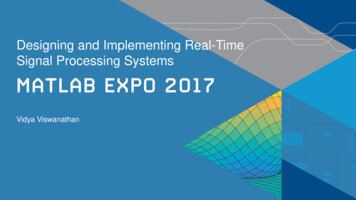
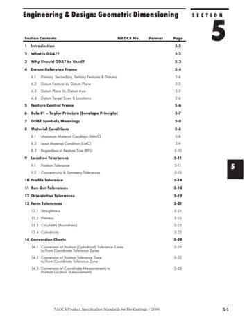
The TURTLE Method3The revisited TURTLE method introduces a "dimensioning step"between the requirements capture and analysis steps. A DimensioningDiagram (DD) is created to describe the network in terms of trafficand equipments behavior. A dimensioning oriented use-case diagram, orDUCD for short, is introduced to document the DD and categorizes theflows conveyed by the network. The information contained in the DDand the DUCS is provided as input to the Network Calculus Software(NCS) that has been interfaced with TTool. NCS analytically computesupper bounds for network parameters such as communication delaysand queues lengths (i.e. memory usage). The NCS output values areused at the design level to have an accurate model of the pre-existingservice.The paper is organized as follows. Section 2 surveys related work.Section 3 presents the TURTLE toolkit and the Network Calculus fundamentals. Section 4 revisits the TURTLE method and introduces DDsas well as DUCSs. In section 5, the proposed approach’s applicabilityis assessed on a video conference application. Section 6 concludes thepaper.2. Related WorkThe increasing complexity of distributed systems and the need forarchitecture validation have stimulated research work on protocol modeling using Petri nets [Dia89], formal description techniques (Estelle,SDL and LOTOS) and UML profiles (such as TURTLE) that bridge thegap between the UML and formal methods world. Much work done inthis area addresses language definitions, formal verification tools andcode generators. A survey of the literature indicates that too little attention has been paid on methodological issues with some exceptions, suchas [AdSSPA06].The methodologies that apply to distributed systems commonly identify communication architecture validation as a fundamental issue, andreuses the three-layer pattern described in figure 1. Two or several protocol entities rely on some pre-existing communication service to offerto their upper users a value-added service. The pattern has extensively
4Studia Informatica Universalis.been used since the mid-1980’s, including for protocol engineering based on UML [Pop06].Figure 1 – Three-layer architectural patternThe increasing use of the UML gives protocol engineers a notationto share. The acceptance of UML among practitioners also depends onthe capacity of UML tools to offer model analysis techniques. For instance, the proSPEX method [dWK05] implements performance evaluation into TAU G2, a tool which supports a UML/SDL profile. De Wetreand Kritzinger promote a non analytical technique based upon simulations and application of queuing theory. Consequently the networkparameters are approximated by lower bounds.Unlike this approach, the one suggested in this paper is based onthe use of analytical realistic upper bounds to characterize the communication service (e.g. transmission delays, throughput or memory)thanks to the Network Calculus formalism. This theory is well adaptedto controlled traffic sources and provides easily analytical upper boundsof the system’s features. Our work joins the use of UML profile andthe Network Calculus theory for dimensioning purposes. To our bestknowledge, this kind of approach has not been addressed yet for distributed systems. However, it is worth to note that in terms of joint use ofNetwork Calculus and a high-level modeling language, there are someexisting tools like CYNC [?] which associates the Network Calculuswith Matlab/Simulink. Moreover, the idea to compute bounds to comeup with worst-case scenarios is not exclusive to the Network Calculus.
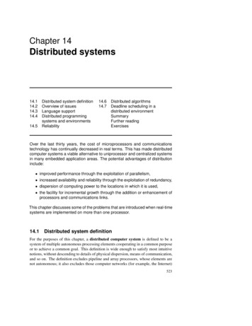
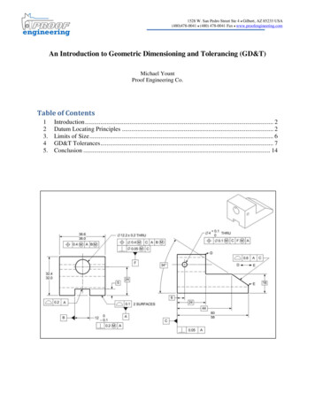
The TURTLE Method5For example, the synchronous language SCADE is proposed in [?], butit does not target distributed systems.3. Background3.1. Protocol engineering with TURTLETURTLE (Timed UML and RT-LOTOS Environment) is a graphiclanguage for requirement capture, use case driven and scenario-basedanalysis, architectural and behavioral design, and rapid prototyping ofreal-time and distributed systems. TURTLE customizes SysML andUML diagrams, and gives them a formal semantics (Note : requirementand use case diagrams remain informal). The TURTLE toolkit, or TTool[?] for short, offers real-time and distributed systems designers a set ofdiagram editors, code generators and user-friendly interfaces to formalverification tools. The UPPAAL and LOTOS/RT-LOTOS code generators enable application of model checking and labeled transition systems minimization techniques. The Java code generator enables rapidprototyping of distributed applications.The TURTLE method applicable to distributed systems is sketchedby Figure 2. A spirals denotes an incremental process where diagramsare gradually introduced and step by step formally verified.Figure 2 – TURTLE method for protocol engineering
6Studia Informatica Universalis.– Requirement capture : TURTLE reuses SysML RequirementDiagrams to create a tree-structure of requirements expressed in plaintext and associated with chronograms that pictorially and formallyexpress temporal requirements. Each formal requirement is unambiguously identified and traced through the life cycle using a traceabilitymatrix.– Analysis : A use case diagram sets the boundary of the distributedsystem and identifies actors, including the underlying service and theupper-layer users. A set of use-case identify the main functions to beimplemented by the system. For a connection-oriented protocol, a usecase may identify a protocol phase, such as the connection set up. Theuse cases are documented by Sequence Diagrams (SD) structured by anInteraction Overview Diagram (a UML2 activity diagram whose nodesare either IODs or SDs). A first group of sequence diagrams depictservice scenarios. A service scenario considers the system as a singleblack box that interacts with actors, namely the underlying serviceand the end-users. The service scenarios are split up into protocolscenarios that make the protocol entities, their upper layer users and theunderlying service explicitly appear. TTool does not restrict applicationof formal verification to design diagrams. It may generate (RT-)LOTOSor UPPAAL code from one IOD and the SDs associated with thatIOD. Though SDs are not intended to represent the entire system, it isnevertheless recommended to perform formal verification on analysisdiagram, as first error filter.– Design : TTool includes a design diagram synthesizer which takesas input analysis diagrams, i.e. the high-level IOD1 and the sub-IODSor SDs referred from IOD1. An object diagram is created. It reusesthe 3-layer pattern depicted by Figure 1. Activity diagrams are alsocreated. They describe the behaviors of the objects. The synthesisalgorithm applies to all analysis diagrams that are implementable[Loh03]. In brief, the implementability of analysis diagrams impliesthat one at least has the same set of traces the analysis diagrams have.The automatically synthesized diagrams may be extended manually inorder to make the design model closer to the real system. The level ofdetail should not hamper application of reachability techniques, and byextension of model-checking and graph minimization techniques that
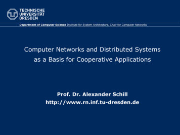
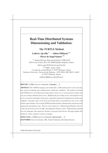
The TURTLE Method7permit to characterize the service rendered by a protocol layer.– Deployment : The model considered at the design step is averification-oriented model that surrounds the protocol machines withtheir upper and lower layers. The deployment step (not discussed in therest of the paper) isolates the protocol machines and enriches them withJava code, thus creating an implementation prototype. New objects maybe created at that occasion and gathered with the protocol machines tocreate software components that will eventually been deployed on thenodes identified by a deployment diagram.3.2. Network Calculus FundamentalsThe Network Calculus formalism [LT01] relies on min-plus algebrafor designing and analyzing deterministic queuing systems where thecompliance to some regularity constraints suffices to model the traffic.These constraints limit traffic burstiness in the network and are described by the so called arrival curve α(t), while the availability of thecrossed node is described by a service curve β(t). The knowledge of thearrival and service curves enables the computation of the delay boundthat represents the worst case response time of a message, and the backlog bound that is the maximum queue length of the flow. The backlogbound helps configuring the memory of the system.As shown in Figure 3, the delay bound D is the maximal horizontaldistance between α(t) and β(t). The backlog bound B is the maximalvertical distance between them. Two conditions make the bounds easierto calculate : (i) a linear arrival curve α(t) b rt with b the maximalburst and r the rate (we say that the flow is (b, r)-constrained) ; (ii) arate latency service curve β(t) max(0, R(t T )) with latency T andrate R. The obtained bounds are Rb T for the delay and b rT for thebacklog. The previous linear arrival curve and rate-latency service arewell adapted to the video-conference system which serves as case studyfor the paper.
8Studia Informatica Universalis.Dataβ(t)α(t)RrbDTTimeFigure 3 – How to compute the maximum bound on delays and queuesThis formalism gives an upper bound for the output flow α (t), initially constrained by α(t) and crossing a system with a service curveβ(t),using min plus deconvolution where :α (t) sups 0 (α(t s) β(s)) (α β)(t)The output arrival curve of the flow α(t) in the case of a linear input arrival curve α(t) and a rate-latency service curve β(t) is simplyα (t) b r(t T ).4. Revisiting the TURTLE methodThe expected benefits of improving the TURTLE method and toolkit with NC-based dimensioning is to integrate realistic analytical upperbounds on transmission delays and other parameters (throughput, memory usage) in order to enhance the model of the system and to obtaina more accurate design.4.1. Basic ConceptsThe revisited TURTLE method depicted by figure 4 integrates figurea dimensioning step, which uses a DD and a DUC. The DD characterizes the network by the following information :– The Equipments connected to the
col scenarios description, protocol machines elaboration as premises to communication architecture validation, and deployment of software components over nodes. The design step uses a three-layer architectural pattern where two or several protocol entities rely on a pre-existing communication service to provide their end user with a value-added .