Transcription
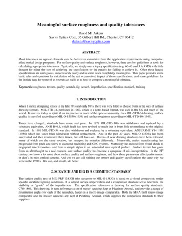
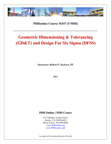
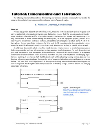
Tutorial: Dimensioning and TolerancesThe following material addresses those dimensioning and tolerance principles necessary for you to detail thedesign and manufacturing processes used to make your team's Pipsqueak engine.1. Accuracy, Clearness, CompletenessAccuracyProcess equipment depends on reference points, lines and surfaces (typically planes in space) thatcan be calibrated using equipment processes. Calibration means that the process equipment determine a reference location and/or orientation to make relative process moves, such as moving a cutting tool relative to metal. When making volumetric parts, as in the Pipsqueak project, process accuracy requires one or more calibrated surfaces. We call this reference plane a datum plane. A set of datum planes form a coordinate reference for the part. In 3D manufacturing the coordinate systemwould be an X-Y-Z reference frame (or coordinate set). A datum can be lines or specific points as well.A calibrated datum(s) is what a machine needs to make relative moves to create features such asholes, countersinks, and cuts. It is important to have a datum for all dimensions. For each dimension thatyou have you need to have a tolerance associated with it. Tolerances are measurements of acceptabledimensional error or variation. This is especially important for parts that may fit into another (e.g. a piston or a bushing). If you have a shaft that fits too loosely within a bushing bearing surface, because yourbushing tolerances were too large, there can be lots of unwanted vibrations, which will cause prematurefailure. Or if your shaft is too big and can’t fit through the bushing, an additional manufacturing processwill be required. What might it be? Many issues can be fixed by using a common datum and applyingacceptable tolerances.Figure 1.1 Courtesy ant-to-always-usetolerances/#Dimensioning and Tolerances Tutorial1 Page
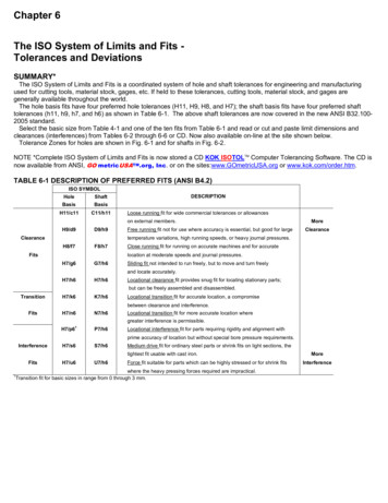
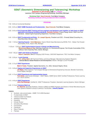
In Figure 1.1, how far away is datum B from datum D?For 1(b): distance (J 0.05) (K 0.05) (L 0.05) (dimensioned length) 0.15For 1(c): distance (dimensioned length) 0.051(b) could lead to tolerance variations of 0.15 while 1(c) leads to a smaller tolerance variation.0.15 variation is more than enough to bind up a pipsqueak engine. The accumulation of tolerancesshown in 1(b) can occur because of the production processes you use, or inconsistent datum(s). Your tolerances will be determined by the machining process that you use, by the requirements of the part, andby the cost associated with the part. Common machine tolerances can range from /-0.02” to /0.0005”. Also note that if you choose multiple datum's you will have to recalibrate your mill or lathe,which takes time.From the reference in Figure1.1: "This range of allowable dimensions is the tolerance band. Thelarger the difference between the upper and lower limits, the larger the tolerance band, also considered a “looser” tolerance. Conversely, the smaller the difference, the smaller the tolerance band, also considered a “tighter” tolerance. Tolerances should always be used. Always. Ambiguity is notyour friend. If you leave a dimension without a tolerance, no one else will know the importance, orthe unimportance, of that dimension."ClearnessAll drawings should be clear. If you are unsure about how to draw a dimension, as a rule of thumb gowith what is cleaner to the eye. For a FULL list of dimensioning and tolerance standards hDesignII/Catalogs/ASME Y14.5M1994 Dimensioning and Tolerancing.pdfCommon dimension symbols (like diameters, threading and countersinks) will be discussed in anothersection. Another way to make the drawings clearer is types of views, which will be discussed in greaterdetail in the readability section.CompletenessCompare the pictures below. Assuming these are flat disks, where would you make the holes (thesmall round circles)?GoodDimensioning and Tolerances TutorialBad2 Page
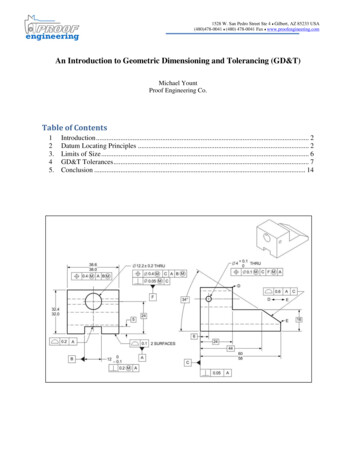
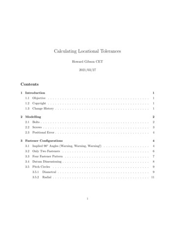
Figure 1.2 courtesy DesignII/Catalogs/ASME Y14.5M1994 Dimensioning and Tolerancing.pdfThe right drawing in Figure 1.2 is an example of an under-dimensioned drawing. This is confusing tomanufacturing personnel and the drawing will be sent back for editing.Another type of error corresponding to completeness is having a drawing that is over-dimensioned.An example of over-dimensioning is shown in Figure 1.3. Over-dimensioning a drawing is just as confusing as under- dimensioning.If you have dimensions that are not consistent you will create confusion and manufacturing personnel will have to pick a dimension or ask for clarification, which delays the production process and costs .Figure 1.3 Courtesy of: http://www.engineeringessentials.com/ege/tol/ex over dim.pngDimensioning and Tolerances Tutorial3 Page
2. Dimensions and CalloutsClarity and Efficiency in DrawingDimensioning should follow these guidelines: Accuracy: correct values must be given. Clearness: dimensions must be placed in appropriate positions. Completeness: nothing must be left out, and nothing duplicated. Readability: clutter, intersectinglines, and wordiness should be minimized.Dimensioning ConventionsDimensions should be placed on the face orview of the object that describes the featuremost clearly. Avoid dimensioning to hiddenlines and between dissimilar surfaces (i.e. flatto round).Holes, radii, and threads should be dimensioned on a view facing the observer. Otherwise this can lead to feature ambiguity. Centerlines and axes should be shown to clearlymark the center of a circular feature. Dimensioning to these lines is not only allowed, butencouraged.If possible, dimensions should be stackedusing one datum. Stacking dimensions allowsfor the use of one datum for multiple features.Repeatedly measuring from one point to another will lead to inaccuracies; see Accuracy,Clearness, and Completeness section. It is often better to measure from one end to various points. This gives the dimensions a reference standard.It is helpful to choose the placement of thedimension in the order in which a machinistwould create the part. This convention maytake some experience. This saves time for themachinist and also adds more clarity to thedrawing. Using the same datum for multipledimensions allows the machinist to edge findor “zero- out" the machine just once beforemaking several features. (For more info, visit:Figure 2.1 Courtesy of:Source: MIT ing-2009/relatedresources/drawing and b/library/enginfo/drawings/index.html)Figure 2.2It is not necessary to place a dimension onevery feature. If a feature, such as a hole or anotch, is repeated on a part, preferred procedure is to only dimension one of the features. This reducesDimensioning and Tolerances Tutorial4 Page
the number of dimensions on a drawing without reducing the amount of information, reducing clutterwhile preserving clarity.There are several different ways to indicate a repeating feature on a drawing. In Figure 2.2 a repeating dimension may be indicated by a number followed by an X, to denote “this dimension repeats fourtimes.” Another method includes putting TYP. or TYP. OF (for “typical of”) followed by a number, denoting the number of features that this dimension should be applied to.If there are several repeated features, make sure to help those that interpret the drawing clearlydistinguish which features correspond to which dimensions. Options for this include marking certain holesor features with matching letters, including a dashed or dotted pitch circle for holes in a circular pattern,or including dashed or dotted lines between duplicate features.Now examine Figure 2.3 and see if you can tell where each feature’s duplicates are located. Fromwhat you have learned so far, is this a good drawing? Why or why not?(For more info, visitFigure 2.3 Feature dimensioninghttp://www.maelabs.ucsd.edu/mae guides/cad/dimensioning/dimensioning fundementals.htm)Dimensioning and Tolerances Tutorial5 Page
CalloutsCallouts are brief, informative descriptions located on the drawing itself. Callouts provide neededadditional information without causing clutter, so symbols and abbreviations are used quite frequently.Typical symbols, abbreviations, and their definitions are found in Table 2.1:Table 2.1 Callout symbols(For more information, visit g2302-2/reading-list/threads)While most CAD programs will automatically create callout notes complete with these symbols, it isstill strongly encouraged that designers familiarizethemselves with these symbols, their definitions, anduses, especially when custom or non-standard features are being made.For threads and holes, thread dimensions shouldbe attached to the hidden line of the feature. (dashedcircle surrounding the circle indicating the hole diameter in Figure 2.4).Thread and hole notes should include the nominal diameter, thread specification, and depth. Blindhole depth can be defined with the DP (deep) symbol.If a through hole is desired, THRU can be included inthe callout. However, if no depth is defined in thenote, a through hole is assumed by convention.Figure 2.5 shows some examples of hole callouts.Dimensioning and Tolerances TutorialFigure 2.4 Callout for threaded hole6 Page
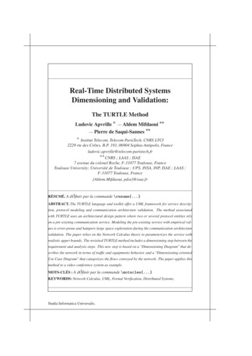
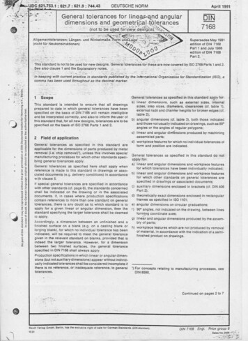
Figure 2.5 Callout examplesSee if you can read the all of the callouts in complete sentences. For example, the first (left) calloutsays, “Drill a 10 mm diameter hole through this location, then counterbore the hole at a 20 mm diameterdown 8 mm.” A cross-sectional view of how the features look is given as well.From these examples it is very easy to see the usefulness of callouts and dimensioning symbols. A lotof information is conveyed using only a few characters.Dimensioning and Tolerances Tutorial7 Page
3. Process SheetsWhy Process Sheets?As clear, concise, and informativeas drawings can be, process sheets arestill necessary to successfully make apart, as design drawings can be confusing; see Figure 3.1.Process sheets provide instructionsfor machinists to follow in order toquickly and correctly make each part,to avoid process problems; see Figure3.2.More Process SheetsProcess sheets come in all shapesand sizes; see Figure 3.3. We will beusing a specific template provided onLearning Suite.Process sheets should include: Clear sequence of processes Material specifications Process equipment to be used Short description of all operations, in proper order Equipment settings (such asfeeds & speeds) Tool types, names and numbersFigure 3.1 Drawing confusionFigure 3.2 Process gone wrong!Dimensioning and Tolerances Tutorial8 Page
Figure 3.3 Process sheet exampleHomework QuestionWrite out a process sheet (using the Template on Learning Suite) for changing a tire. Print out your process sheet and turn it in.Dimensioning and Tolerances Tutorial9 Page
4. ReadabilityWhen making engineering drawings, readability refers to using the correct views in a way that is botheasy to read and transmits all of the required information to build the part. In this section we will propose important principles that you need to apply when making your Pipsqueak engine drawings.Cross SectionFigure 4.1 shows a cross sectional view with an additional side view to visualize the inside of thepart. The correct formatting of this, as seen above, shows a dotted line along the cross sectional areawith two arrows perturbing from the end. These arrows point towards the cross section. The cross section is then labeled “Section A-A” corresponding to the letters on the drawing.Figure 4.1 Cross sectionIsometric ViewsIsometric views are also used on a drawing page and the exploded view to provide a 3-D model visualization. These are often located on the top right hand side of the page as shown in Figure 4.2.Dimensioning and Tolerances Tutorial10 P a g e
Figure 4.3 Isometric viewExploded View (Assembly Drawing)Another page that you will want to make is an exploded view, as shown in Figure 4.4.Figure 4.4 Exploded viewDimensioning and Tolerances Tutorial11 P a g e
This view will be a guide for you and the reader to make sure that you have all the parts that youneed. Also important in Figure 4.4 the list of parts with their quantity and a balloon showing where theyfit within the drawing assembly. This list does not replace the Bill of Materials that you need to makebecause a Bill of Materials talks about the stock parts from whence your parts are made. The explodedview shows the finished parts and how you will assemble them. Lastly for the exploded view don’t forget to show your isometric view of the assembled design.Bill of Materials (BOM)Another important part of readability is a Bill of Materials (BOM). A Bill of Materials is a tabulated listthat lets the machinist know what materials and components needed to make your part. These stockcomponents will then be used with your drawings and your process sheets (sheets that explain how tomake the part) to create the individual parts. The stock components for the Pipsqueak will be given toyour team so be sure you use those stock parts on your Bill of Materials.Table 4.1 Sample BOMReally good suggestion: Remember that cleanliness is next to Godliness. Keeping everything clean andorderly means that your part will be made correctly and ultimately your team will receive a good projects grade.D&C 88:119: "Organize yourselves; prepare every needful thing; and establish a house, even a house ofprayer, a house of fasting, a house of faith, a house of learning, a house of glory, a house of order, a houseof God;"Dimensioning and Tolerances Tutorial12 P a g e
When making engineering drawings, readability refers to using the correct views in a way that is both easy to read and transmits all of the required information to build the part. In this section we will pro-pose important principles that you