Transcription
PDHonline Course M347 (5 PDH)Geometric Dimensioning & Tolerancing(GD&T) and Design For Six Sigma (DFSS)Instructor: Robert P. Jackson, PE2012PDH Online PDH Center5272 Meadow Estates DriveFairfax, VA 22030-6658Phone & Fax: 703-988-0088www.PDHonline.orgwww.PDHcenter.comAn Approved Continuing Education Provider
www.PDHcenter.comPDH Course M247www.PDHonline.orgTABLE OF CONTENTSPART IINTRODUCTION5DESIGN FOR SIX SIGMA (DFSS)5DFSS TOOLS7IDENTIFY 0R DEFINE8IMPORTANCE OF SIX SIGMA GOALS9MEASURE AND ANALZSE11DESIGN12APPLICATION SOFTWARE12DESIGN TO OPTIMIZE13VALIDATE14PART IIGEOMETRIC DIMENSIONING AND TOLERANCING (GD&T)14GD&T STANDARDS15BENEFITS16RULES17SYMBOLS18MODIFYING TOLERANCES SYMBOLS19GD&T EXAMPLES19FEATURE CONTROL FRAME23READING BASIC SYMBOLS25PART IIIDFSS & GD&T28TOLERANCE ALLOCATION28STATISTICAL ALLOCATION30EXAMPLES32 Robert P. JacksonPage 2of 39
www.PDHcenter.comPDH Course M247www.PDHonline.orgLIST OF FIGURESFigure 1Focus for Six Sigma (DFSS)7Figure 2Reliability Goal Setting9Figure 3Process Capability Between 3 Sigma and 6 Sigma10Figure 4DFSS Process14Figure 5Tolerance Classes19Figure 6Spline Assembly20Figure 7Handle Using GD&T20Figure 8Linear Dimensioning21Figure 9Collar (GD&T)22Figure 10Collar in English Only23Figure 11Feature Control Frame23Figure 12Flatness, Runout, Perpendicularity26Figure 13MMC, LMC26Figure 14Basic Dimension27Figure 15Steps for Evaluating “Gap” Allocation31Figure 16GE Lower Drawer32Figure 17Loop Diagram33Figure 18Motor Assembly36Figure 19Refrigerator Door Trim36Figure 20Refrigerator Door Trim Enlargement37Table 1Differences Between Six Sigma and DFSS6Table 2Six Sigma vs DPMO & RTY7Table 3DFSS Tools8Table 4GD&T Characteristics24Table 5Modifying Tolerance Symbols25Table 6Standard Deviation vs Process29Table 7Standard Deviation vs Process29LIST OF TABLES Robert P. JacksonPage 3of 39
www.PDHcenter.comPDH Course M247www.PDHonline.orgTable 8Tolerance Allocation Spreadsheet30Table 9Dimensions and Mean Values32CONCLUSIONS:38REFERENCES:39 Robert P. JacksonPage 4of 39
www.PDHcenter.comPDH Course M247www.PDHonline.orgGeometric Dimensioning & Tolerancing (GD&T) and Design For Six Sigma (DFSS)Robert P. Jackson, P.E.INTRODUCTION:This course is basically intended to address two distinct, but related, areas of engineering design: 1.) DESIGN FORSIX SIGMA (DFSS) and 2.) GEOMETRIC DIMENSIONING AND TOLERANCING (GD&T). Both concepts have beenviable approaches to design and detailing for some years and both are extremely valuable and useful tools for thepracticing engineer. DFSS is a statistical method of design that can serve as a predictive tool to greatly improvequality control, if used properly and consistently. GD&T is a well accepted methodology of detailing thecharacteristics, dimensions and tolerances of a component or assembly of components. The GD&T methodology isprescribed by ASME / ANSI Standards Y 14.5M‐1994 and Y14.5‐2009. This course uses the tenants of DFSS ANDGD&T to fully define a mechanical component, or assembly of components, so that no more than 3.4 defects perone million parts will result when in use. DFSS and GD&T are usually taught as separate subjects but certainlycomplement each other as far as design tools. It is much more difficult to achieve six sigma (6σ) results withoutusing the GD&T approach. By using standard linear dimensioning instead of GD&T, huge errors can be made thatleave room for doubt when designing tools and dies for fabrication. This will become apparent as we addressGD&T. For this reason, I am structuring the course to include, and integrate, both methodologies. I would like tostate that the treatment of DFSS and GD&T will be somewhat general and not in depth as far as mathematicalmodeling, which sometimes accompanies courses of this nature. There are excellent texts available on bothsubjects but none that I have found integrating both disciplines. The combination of these two is definitely alogical presentation for “blue‐collar,” goal‐oriented, working engineers and engineering managers.The course is divided into four distinct divisions; i.e. 1.) DFSS Survey, 2.) GD&T Survey, 3.) Problem solving thatshows how DFSS and GD&T interact and compliment each other AND 4.) Teachable QUIZ. Please note that I havechosen to construct the Quiz at the end of the course to be a learning experience. Several of the questions havedescriptive information important to understanding the basic tenants of Six Sigma and GD&T. This descriptiveinformation may not be in the body of the text itself.I hope to achieve an interest that will provide impetus for engineers and engineering managers to adopt bothdisciplines for their companies. I would also state that by using DFSS, GD&T AND the tenants of ReliabilityEngineering and Reliability Testing, a product can be designed and manufactured to satisfy the most critical enduser, for either consumer or commercial products.PART IDESIGN FOR SIX SIGMA (DFSS):DFSS is the application of Six Sigma principles to the design of components, subassemblies, completed productsand their manufacturing and support processes. Six Sigma, by definition, focuses on the production phase of aproduct. DFSS focuses on the research, design and development phase of a project and is truly a design tool thatcan and should be used by the design engineer to meet consumer expectations and demands. The goal of DFSS isto implement the Six Sigma methodologies as early in the product or service life cycle as possible, therebyguaranteeing the maximum return‐on‐investment (ROI). The methods used to insure rigor in both processes aresomewhat different. Six Sigma uses the DMAIC approach (Define, Measure, Analyze, Improve, Control). DFSS usesDMADV (Define, Measure, Analyze, Design and Verify). Please note that DFSS strives to meet the same goals as SixSigma, that being no more than 3.4 defects per million. In this respect, the end results are the same. The tablebelow will give a very brief description of the differences between the two technologies. Robert P. JacksonPage 5of 39
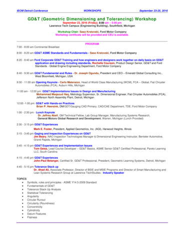
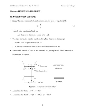
www.PDHcenter.comPDH Course M247www.PDHonline.orgDIFFERENCES BETWEEN SIX SIGMA AND DFSSSIX SIGMADFSSDMAIC: Define, Measure, Analyze, Improve, ControlDMADV: Define, Measure, Analyze, Design, ValidateDMADOV: Define, Measure, Analyze, Design,Optimize and ValidateLooks at existing processes and fixes problems.Focuses on the up‐front design of the product andprocesses.More ReactiveMore proactive.Dollar benefits obtained from 6σ can be quantified quickly.Benefits are more difficult to quantify and tend tobe more long‐term. It can take six to twelve monthsafter launch of the new product before you willobtain proper accounting on the impact.Product performance accomplished by “build and test.”Product performance modeled and simulated.Performance and producibility problems fixed afterDesigned for robust performance and producibility.Product in use.Quality testedQuality “designed into” the product.Table 1: Differences Between 6σ & DFSSWith DFSS you are designing quality into the component or product from the very start and hopefully eliminatingwaste by minimizing manufacturing variation before it happens. This approach allows for correcting problems up‐front and can significantly reduce the costs of redesign and testing. It is also a great way to meet customerdemands by establishing measurable goals. DFSS attempts to predict how the designs under consideration willbehave and how to correct for manufacturing variation prior to the first production run.A graphical representation of the difference between DFSS and Six Sigma may be seen as follows, relative toproduct costs. Robert P. JacksonPage 6of 39
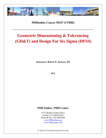
www.PDHcenter.comPDH Course M247www.PDHonline.orgFigure 1—Focus for DFSS vs Six Sigma [ 3 ]Again, you can see that we want to implement DFSS at the research, design and development stages and earlyenough in the project so that we may introduce the component or subassembly with minimal manufacturingvariation. This is the point where costs are at their lowest and changes are “doable” in considerably less time andwith considerably less expenditure of capital or human resources.DFSS TOOLS:In looking at the tools used with DFSS, the following, Table 3, represents the entire process, broken down by majoraction items. Please keep in mind that we “pick and choose” the best approach to Identify, Design, Optimize andValidate. All steps along the way may not be needed and would represent considerable duplication of effort. WEWISH TO PRODUCE A MAUNFACTURED PRODUCT THAT WILL EXHIBIT NO MORE THAN 3.4 DEFECTS PER MILLIONOPPORTUNITIES AND WITH THE MAXIMUM “ROLLED THORUGHPUT YIELD”. The table below will demonstrateour objectives.σ CAPABILITYDEFECTS PER MILLION OPPORTUNITIESROLLED THROUGHPUT YEILD2σ308,53769.1%3σ66,80793.3 %4σ6,21099.4 %5σ23399.97 %6σ3.499.99966%TABLE 2—SIX SIGMA VS DPMO AND RTY Robert P. JacksonPage 7of 39
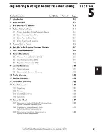
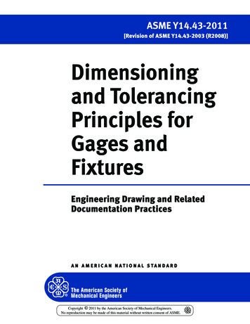
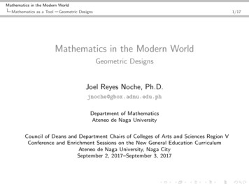
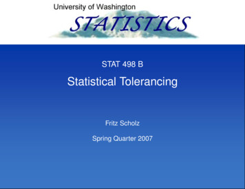
www.PDHcenter.comPDH Course M247www.PDHonline.orgTABLE 3—DFSS TOOLS [ 3 ]Let us quickly look at each action item and define the activity required before advancing on to the next phase ofthe DFSS process.IDENTIFY OR DEFINE:The most critical part of the process is the very first phase, IDENTIFY. This is the step that basically asks thecustomer, “what do you want” then that answer, usually given in generalities, is quantified into engineeringspecifications. I want it this big, this color, this weight, these features, etc becomes an engineering specificationAND engineering drawing that can be interpreted by a model shop, a tool and die maker and quality controlinspectors. The process for doing just this is called Quality Functional Deployment or QFD. QFD is a process thatdetails and ranks the most desirable features deemed important by the consumers. Well‐defined andunambiguous requirements are absolutely necessary and will lessen the probability of “false starts” and “detours”in the development process. We wish to minimize the inconsistencies between articulation of functionalrequirements and the definition of system requirements and parameter target values. A matrix of features isdeveloped and rated for desirability so engineering can translate those features into “hard” specifications. Thefollowing sketch will indicate one possible approach for doing just that. Robert P. JacksonPage 8of 39
www.PDHcenter.comPDH Course M247www.PDHonline.orgFigure 2 Reliability Goal Setting [20]This initial phase; i.e. QFD, allows for production of the Design Guidance model and ultimately lets us “kick thetires” of the very first prototype. We go back to marketing, show them the drawings and / or prototype for theirapproval. Revisions are made based upon their desires and needs. We may wish to reconvene the focus group ofpotential users to get their impressions and verify that their needs and demands will be ultimately met by partsfrom the first production run. Next in the process is 1.) Design Confirmation, 2.) Pre‐Pilot, 3.)Pilot and finally, 4.)The first production of the component or assembly. The Identify phase is also where the project team is selectedand charged with the responsibility for “engineering” the component. A team leader is chosen as well as all of theteam members, from CAD, model shop, evaluation testing, reliability testing, etc. It is recommended thatrepresentatives from quality and manufacturing be included so that all critical functions can have a voice in thedesign of what will become the final product. If the product is similar to an existing design, benchmarking willbecome necessary to evaluate current field failure rates, manufacturing difficulties, issues with tooling, problemswith packaging and shipping so that these mistakes will not occur in the new product. Benchmarking can identifyparts that do not survive stated reliability goals. This is a very critical part of IDENTIFY. One excellent tool for thisexercise is FAILURE MODE EFFECT ANALYSIS or FMEA. FMEA is a technique that allows for cataloging of eachpossible failure mode of a component or an assembly during normal use. I highlight the word normal here. TheIDENTIFY phase selects the initial CRITICAL TO QUALITY CHARACTERISTICS (CTQs) of the components orassemblies. These CTQs define the most critical dimensions, features and specifications of parts AND specifies thatthose items MUST be checked on first piece samples prior to any pilot or production run. Generally, a sample sizeof thirty parts or assemblies is required to gather enough CTQ statistically‐significant data. The CTQs areperiodically checked after production is initiated to make sure there is no depreciation of the manufacturingprocesses. Audits are definitely recommended to insure strict compliance with quality standards for these CTQs.IMPORTANCE OF SIX SIGMA:Before we leave IDENTIFY, I would like to restate the importance of meeting Six Sigma goals. Right now, mostmanufacturing companies are producing to a three‐Sigma standard. Three Sigma produces a 93.32 % long‐termyield. Reaching these goals gives us the following meaning of 3 Sigma‐‐‐“good”. 20,000 lost articles of mail per hour. Unsafe drinking water for approximately fifteen minutes per day. 5,000 incorrect surgical operations per week. Two short or long landings at most major airports each day. 200,000 wrong drug prescriptions each year. No electricity for almost seven hours each month. Robert P. JacksonPage 9of 39
www.PDHcenter.comPDH Course M247www.PDHonline.orgEven if we look at the profile of a 4 σ company we find the following characteristics1.) Profitable and growing but with a decreasing market share.2.) Market prices declining for certain products or product lines.3.) Competitors increasing4.) Has quality assurance program but deficiencies keep “slipping” through the Q.C. process.5.) Spending 10‐25% of sales dollars on repairing or reworking product before it ships. ( This is crucial and afact that will surface during benchmarking.)6.) Unaware that best in class companies have similar processes that ar
GD&T to fully define a mechanical component, or assembly of components, so that no more than 3.4 defects per one million parts will result when in use. DFSS and GD&T are usually taught as separate subjects but certainly complement each other as far as design tools. It is much more difficult to achieve six sigma (6σ) results without