Transcription
CHAPTER1Introduction toGeometric Dimensioningand TolerancingFor many in the manufacturing sector, geometric dimensioning and tolerancing (GD&T) is anew subject. During World War II, the United States manufactured and shipped spare partsoverseas for the war effort. Many of these parts, even though they were made to specifications, would not assemble. The military recognized that defective parts caused serious problemsfor military personnel. After the war, a committee representing government, industry, and education spent considerable time and effort investigating this defective parts problem; this groupneeded to find a way to ensure that parts would fit and function properly every time. The resultwas the development of GD&T.Ultimately, the USASI Y14.5–1966 (United States of America Standards Institute, predecessorto the American National Standards Institute) document was produced based on earlier standards and industry practices. The following are revisions to that standard: ANSI Y14.5–1973 (American National Standards Institute) ANSI Y14.5M–1982 ASME Y14.5M–1994 (American Society of Mechanical Engineers) ASME Y14.5–2009 ASME Y14.5–2018The 2018 revision is the current, authoritative reference document that specifies the proper application of GD&T.Most government contractors are now required to generate drawings that are tolerancedwith GD&T. Because of tighter tolerancing requirements, shorter time to production, and theneed to communicate design intent more accurately, many companies other than military suppliers are recognizing the importance of tolerancing their drawings with GD&T.Traditional tolerancing methods have been in use since the mid-1800s. These methods do agood job of dimensioning and tolerancing the size of features and are still used in that capacitytoday, but they do a poor job of locating and orienting features of size. GD&T is used extensively for tolerancing size, shape, form, orientation, and location of features. Tolerancing withGD&T has a number of advantages over conventional tolerancing methods; three dramaticadvantages are illustrated in this chapter.The purpose of this introductory chapter is to provide an understanding of what GD&Tis and why it was developed, when to use it, and what advantages it has over conventional tolerancing methods. With a knowledge of this subject, technical practitioners will be101 Cogorno CH01 p001-008.indd 125/09/19 3:42 PM
2Chapter Onemore likely to understand tolerancing in general. With this new skill, engineers will havea greater understanding of how parts assemble, do a better job of communicating designrequirements, and ultimately be able to make a greater contribution to their companies’bottom line.Chapter ObjectivesAfter completing this chapter, the learner will be able to: Define GD&T Explain when to use GD&T Identify three advantages of GD&T over coordinate tolerancingWhat Is GD&T?GD&T is a symbolic language. It is used to specify the size, shape, form, orientation, and locationof features on a part. Features toleranced with GD&T reflect the actual relationship between mating parts. Drawings with properly applied geometric tolerancing provide the best opportunityfor uniform interpretation and cost-effective assembly. GD&T was created to ensure the properassembly of mating parts, to improve quality, and to reduce cost.GD&T is a design tool. Before designers can apply geometric tolerancing properly, they mustcarefully consider the fit and function of each feature of every part. GD&T, in effect, serves as achecklist to remind the designer to consider all aspects of each feature. GD&T allows the designerto specify the maximum available tolerance and, consequently, design the most economical parts.Properly applied geometric dimensioning and tolerancing ensures that every part will assembleevery time.GD&T communicates design requirements. This tolerancing scheme identifies all applicable datum features, that is, reference surfaces, and the features being controlled to thesedatum features. A properly toleranced drawing not only is a picture that communicatesthe shape and size of the part but also tells a story that explains the tolerance relationshipsbetween features.When Should GD&T Be Used?Many designers ask, when should I use GD&T? Because GD&T was designed to position featuresof size, the simplest answer is to locate all features of size with GD&T controls. Designers shouldtolerance parts with GD&T when: Drawing delineation and interpretation need to be the same Features are critical to function or interchangeability It is important to stop scrapping perfectly good parts It is important to reduce drawing changes Automated equipment is used Functional gaging is required It is important to increase productivity Companies want across-the-board savings01 Cogorno CH01 p001-008.indd 225/09/19 3:42 PM
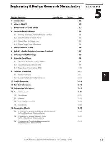
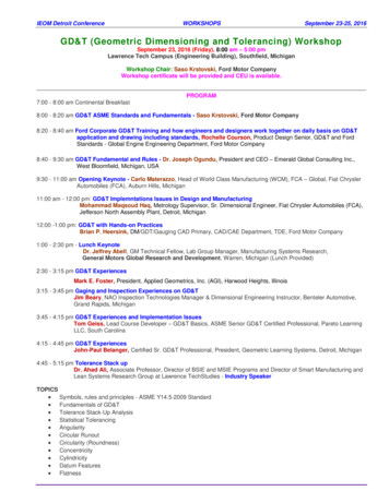
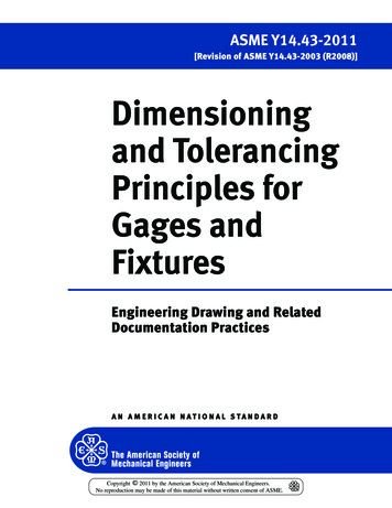
I n t ro d u c t i o n t o G e o m e t r i c D i m e n si o n i ng a n d To l e ra n c i ng3Advantages of GD&T over Coordinate Dimensioning and TolerancingSince the middle of the nineteenth century, industry has been using the plus or minus tolerancingsystem for tolerancing drawings. This system has several limitations. The plus or minus tolerancing system generates rectangular tolerance zones. A rectangular tolerance zone, such as theexample in Fig. 1-1, is a boundary within which the axis of a feature that is in tolerance must lie.Rectangular tolerance zones do not have a uniform distance from the center to the outer edges. InFig. 1-1, from left to right and top to bottom, the tolerance is .005; across the diagonals, the tolerance is .007. Therefore, when designers tolerance features with a plus or minus .005 tolerance,they must tolerance the mating parts to accept a plus or minus .007 tolerance, which exists acrossthe diagonals of the tolerance zones.With the plus or minus tolerancing system, features of size can be specified only at the regardless of feature size condition. Regardless of feature size means that the location tolerance remains thesame, .005, no matter what size the feature happens to be within its size tolerance. If a hole, likethe one in Fig. 1-1, increases in size, it actually has more location tolerance, but, with the plus orminus tolerancing system, there is no way to capture that additional tolerance.Datum features are usually not specified where the plus or minus tolerancing system isused. Consequently, machinists and inspectors don’t know which datum features apply or inwhat order they apply. In Fig. 1-1, measurements are taken from the lower and left sides ofthe part. The fact that measurements are taken from these sides indicates that they are datumfeatures. However, since these datum features are not specified, they are called implied datumfeatures. Where datum features are implied, the designer has not indicated which datum featureis more important and has not specified whether a third datum feature is included. It would beØ3.000-3.030 .0074.00.0102.000 .005.0102.000 .0052.50Unless Otherwise Specified:.XX .01ANGLES 1 Figure 1-1 The traditional plus or minus tolerancing system. The axis of the 3-inch-diameter hole, to be in tolerance,must fall inside of the .010 square tolerance zone.01 Cogorno CH01 p001-008.indd 325/09/19 3:42 PM
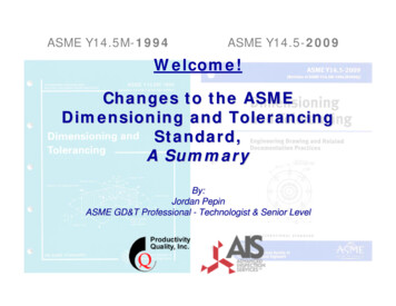
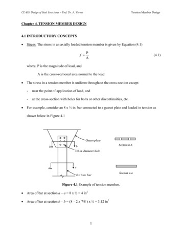
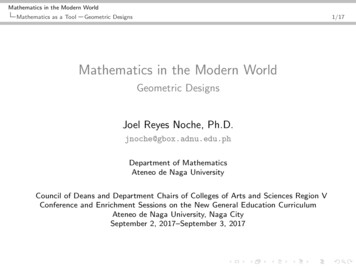
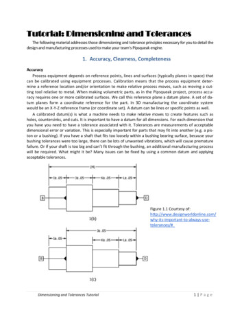
4Chapter Onelogical to assume that a third datum feature does exist because the datum reference frame consists of three mutually perpendicular planes, even though a third datum feature is not implied.When locating features with GD&T, there are three important advantages over the coordinatetolerancing system: The cylindrical tolerance zone The maximum material condition modifier Datum features specified in order of precedenceThe Cylindrical Tolerance ZoneThe cylindrical tolerance zone is located and oriented to a specified datum reference frame.In Fig. 1-2, the tolerance zone is oriented perpendicular to datum plane A and located withbasic dimensions to datum planes B and C. There are no tolerances directly associatedwith a basic dimension; consequently, basic dimensions eliminate undesirable tolerancestack-up. Because the cylindrical tolerance zone is established at a basic 90 angle to datumplane A and extends through the entire length of the feature, it easily controls the orientationof the axis.Ø3.000-3.030Size and Size ToleranceLocation ToleranceØ.014 @ MMCCylindrical Tolerance ZoneAC2.0002.000Location DimensionsFigure 1-2BUnless Otherwise Specified:.XX .01ANGLES 1 The rectangular tolerancezone is .005 in the horizontaland vertical directions.The cylindrical tolerance zone compared with the rectangular tolerance zone.Unlike the rectangular tolerance zone, the cylindrical tolerance zone defines a uniform distance from true position, the theoretically perfect center of the hole, to the tolerance zone boundary.When a .014-diameter cylindrical tolerance zone is specified about true position, there is a01 Cogorno CH01 p001-008.indd 425/09/19 3:42 PM
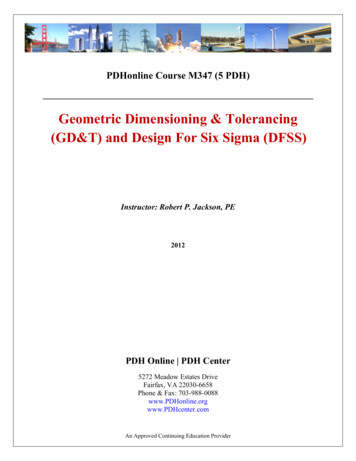
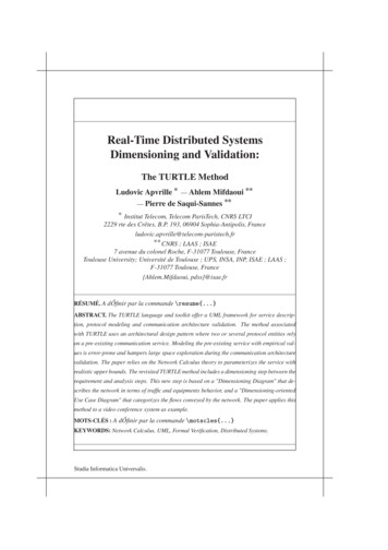
I n t ro d u c t i o n t o G e o m e t r i c D i m e n si o n i ng a n d To l e ra n c i ng51014 .014 Tolerance Zone .0102 .0102 Figure 1-3A cylindrical tolerance zone provides a uniform distance from the axis to the tolerance zone boundary.tolerance if .007 from true position in all directions. A cylindrical tolerance zone circumscribedabout a square tolerance zone, such as the one in Fig. 1-3, has 57% more area than the squaretolerance.The Maximum Material Condition ModifierThe maximum material condition symbol (circle M) in the feature control frame is a modifier. Itspecifies that as the hole in Fig. 1-2 increases in size, a bonus tolerance is added to the tolerancestated in the feature control frame.The limit tolerance in Fig. 1-4 indicates that the hole size can be as small as 3.000 (maximummaterial condition) and as large as 3.030 (least material condition) in diameter. The geometrictolerance specifies that the hole be positioned with a cylindrical tolerance zone of .014 in diameter when the hole is produced at its maximum material condition size. The tolerance zone isoriented perpendicular to datum plane A and located with basic dimensions to datum planes Band C. Since the .014-diameter tolerance is specified with a maximum material condition modifier, circle M, a bonus tolerance is available. As the hole size in Fig. 1-2 departs from maximumMaximum Material Condition (MMC)Least Material Condition (LMC)Ø3.000-3.030 (Hole)Size and Size ToleranceLocation ToleranceMaximum Material Condition SymbolFigure 1-4 The size, size tolerance, and feature control frame for the hole in Fig. 1-2.01 Cogorno CH01 p001-008.indd 525/09/19 3:42 PM
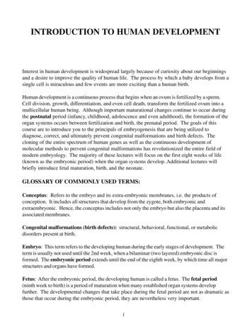
6Chapter Onematerial condition toward least material condition, additional location tolerance, called bonustolerance, is allowed in the exact amount of such departure. If the hole specified by the featurecontrol frame in Fig. 1-4 is actually produced at a diameter of 3.020, the total available toleranceis a diameter of .034.Actual Mating EnvelopeMinusMaximum Material ConditionBonus TolerancePlus3.020 3.000.020Geometric Tolerance .014Total Positional Tolerance.034The maximum material condition modifier allows the designer to capture all of the availabletolerance.Datum Features Specified in Order of PrecedenceDatum features are not usually specified on drawings toleranced with the coordinate dimensioning system. The lower and left edges on the drawing in Fig. 1-5 are implied datum featuresbecause the holes are dimensioned from these edges. But which datum feature is more important,and is a third datum plane included in the datum reference frame? A rectangular part such as thisis usually placed in a datum reference frame consisting of three mutually perpendicular intersecting planes. When datum features are not specified, machinists and inspectors are forced to makeassumptions that could be very costly.2.001.001.00Figure 1-55.00Unless Otherwise Specified:.XX .01ANGLES 1 A conventional drawing with no datum features specified.The parts placed in the datum reference frames in Fig. 1-6 shows two interpretations of thedrawing in Fig. 1-5. With the traditional method of tolerancing, it is not clear whether the loweredge of the part should be resting against the horizontal surface of the datum reference frame asin Fig. 1-6A or if the left edge of the part should be contacting the vertical surface of the datumreference frame as in Fig. 1-6B.Manufactured parts are not perfect. It is clear that, when drawings are dimensioned withtraditional tolerancing methods, a considerable amount of information is left to the machinists’01 Cogorno CH01 p001-008.indd 625/09/19 3:42 PM
I n t ro d u c t i o n t o G e o m e t r i c D i m e n si o n i ng a n d To l e ra n c i ngA7BFigure 1-6 Possible datum feature interpretations of the drawing in Fig. 1-5.and inspectors’ judgment. If a part is to be inspected the same way every time, the drawing mustspecify how the part is to fit in the datum reference frame. Each datum feature must be specifiedin the feature control frame in its proper order of precedence.Summary GD&T is a symbolic language used to specify the size, shape, form, orientation, and location of features on a part. GD&T was created to ensure the proper assembly of mating parts, to improve quality,and to reduce cost. GD&T is a design tool. GD&T communicates design requirements. This text is based on the standard Dimensioning and Tolerancing ASME Y14.5–2018. The cylindrical tolerance zone defines a uniform distance from true position to the tolerance zone boundary. The maximum material condition symbol in the feature control frame is a modifier thatallows a bonus tolerance. All of the datum features must be specified in order of precedence.Chapter Review1.is the current, authoritative reference documentthat specifies the proper application of GD&T.2. GD&T is a symbolic language used to specify the,, and,,of features on a part.3. Features toleranced with GD&T reflect thebetween mating parts.01 Cogorno CH01 p001-008.indd 725/09/19 3:42 PM
8Chapter One4. GD&T was created to ensure the proper assembly of, and to reduce, to improve.5. Geometric tolerancing allows the maximum availableconsequently, the mostparts.6. Plus and minus tolerancing generates a7.and,shaped tolerance zone.generates a cylindrical shaped tolerance zone tocontrol an axis.8. If the distance across a square tolerance zone is .005, or a total of .010, what is theapproximate distance across the diagonal?9. Theto the tolerance zone boundary.defines a uniform distance from true position10. Bonus tolerance equals the difference between the actual mating envelope size and the.11. While processing, a rectangular part usually rests against aconsisting of three mutually perpendicular intersecting planes.01 Cogorno CH01 p001-008.indd 825/09/19 3:42 PM
ANSI Y14.5–1973 (American National Standards Institute) ANSI Y14.5M–1982 ASME Y14.5M–1994 (American Society of Mechanical Engineers) ASME Y14.5–2009 ASME Y14.5–2018 The 2018 revision is the current, authoritative reference docum