Transcription
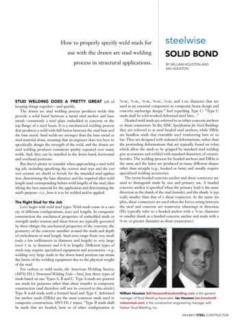
Vol-3 Issue-4 2017IJARIIE-ISSN (O)-2395-4396DESIGN & DEVLOPMENT OF WELDPARAMETER FOR PRESSURE VESSEL ofASTM SA 516 Gr 70P. R. Satpute.1, Prof. C.M.Gajare 212. PG Student, Department of Mech. Engg, SVCET, Rajuri, Pune, Maharashtra, IndiaAssociate Professor, Department of Mech. Engg, KJ College of Engineering and ManagementResearch, Pune,Maharashtra, IndiaABSTRACTThe main objective this technical paper presents is design & development of weld parameter for pressure vessel.Pressure vessel is subjected to many forces & stress due to high pressure rise is produced into the vessel. if thedesign is not proper it caused defects or failure into the fabrication of pressure vessel which deals with the largeaccidental incident in firms. So safety is taken as 1 stconcered about pressure vessel. Pressure vessel is designedaccordance with the principles of American Society of Mechanical Engineers (A.S.M.E.) SEC VIII. Pressure vesselis checked accordance with the principles of American Society of Mechanical Engineers (A.S.M.E.) SEC VIII.Efforts are made in this paper for correction in weld parameter of pressure vessel accordance to follow ASMEcodes & standards for safety operation of pressure vessel.Keywords: Design, Development, Pressure Vessel, Welding, ANSYS1. INTRODUCTIONPressure vessels are those who subjected to serval types of forces & stress acting on both sides of the vessel i.e.inside & outside which caused the pressure difference produced. At this case pressure inside the vessel is alwaysgreater than pressure present at outside. This vessels are container, petroleum tanks, gas carrying pipelines, nozzles,heat exchangers, chemical reactor etc. at all this kind of pressure vessel operating liquid has many property whichaffects on to the design & fabrication of pressure vessel. The properties of liquid are corrosiveness, flammable, highoperating temperature, nuclear material, the material whose phase change occurs into the vessel. Due to such criticaloperating condition design & fabrication of vessel is such that no defect into the joints of vessel & no leakages toavoid further accident due to the vessel.In such case welding this is to be used for joining the various parts of pressure vessel play an important role. Thevarious parameters of weld must be accordance with ASME codes & standards. The welding must be checkedaccordance with ASME codes & standards for safety & smooth operation of pressure vessel. Pressure vessel failureis a major issue for manufactures. This failure can be divided into various categories. The failure of the vesseldepends upon –material, design, fabrication. Above parameter is not properly used which caused failure into thevessel. It is necessary for the pressure vessel joints to be filled with proper welding process & proper material usedfor joining these joints. Also it is necessary the welding parameter which is to set by a design department forspecified pressure vessel. This parameter must be accordance with ASME codes & standards.2. LITERATURE REVIEWVarious researches have been discussed for design & the parameter for welding. They are below6112www.ijariie.com1507
Vol-3 Issue-4 2017IJARIIE-ISSN (O)-2395-4396R. W. Hinton et.al.Studied theWelding Preheat Requirements for Unknown Grades of Carbon and Low AlloySteels also provide the relation for calculating minimum preheat temperature.Zhang Zet.al.The effect of the PWHT studied by the Norton creep law model. Results of this researchshow that thecircumferential residual stress in blade was greater than the vertical residual stress. The residual stresses finally inthe impeller are highly decreased by the PWHT.Prof. Burkul R.Met.al.Studied effect of different welding speed on tensile strength, impact strength, distortions ofweld joint at diff. groove angles & bevel heights. Also suggest good welding speed for max. tensile, impactstrength& for mini. Hardness of heat affected zone.Siva Krishna Raparlaet.al.carried out the researched for design & analysis of multilayeredhigh pressure vessels.The Ansys are used for analyzed multilayeredhigh pressure vessels& calculate stresses developed into the vessels.Luis D. Cozzolino et.al. The mechanisms of post-weld rolling and how it reduces and eliminates residual stress anddistortion are poorly understood. Finite element analysis was applied to two different methods of rolling: rolling theweld bead directly with a single roller and rolling beside the weld bead with a dual flat roller. The models showedthat both rolling techniques were able to induce compressive stress into the weld region, which increased withrolling load. The distribution of stress was sensitive to the coefficients of friction between the workpiece and theroller and the backing bar. High friction coefficients concentrated the plastic deformation and compressive stresswithin the centre of the weld bead. Distortion can be eliminated by rolling; however, the experiments indicated thatthis was only achieved when applied to the weld bead directly.3. PROBLEM STATEMENTIn this project the pressure vessel which is under study made up of carbon steel material & it made to handle forspecial purpose liquid which is at 3100(max value) operating pressure. Here the parameter which set by designdepartment which caused various defects into the weld joints. this defect includes porosity, crack, lack of fusion,inclusion etc. this parameter is as follows:1. Weld preparation (weld angel)The bevel used for welding is single V. the angle is throughout is 37.5degree.2. Preheat temperatureThe preheat temperature is taken as 175-200 degree3.4.Heat treatment& post weld heating temperatureNo interclass heating arrangement to be set for vessel & PWHT is 300 degreesNDT testing stagesNDT testing is to taken after complete welding of 80 mm.4. CODE SELECTIONThe various codes &standards are to use in the project. Reason behind using it to give quality assurance,performance, safety. ASME &EN these two are the major codes &standards used universally for pressure vessel.According to manufacture & buyer point of view ASME standards are used here.ASME section VIII – Rules for construction of pressure vessels Div.1.ASME section IX – Welding QualificationASME section V –Nondestructive testing4.1 Design Considerations A pressure Vessel is designed to ASME Code Section VIII division I. A pressure Vessel welding is designed or done to ASME Code Section IX. A Safety Factor of “3”on Ultimate Tensile Strength is considered in the design of the shell only. For otherparts the Factor of Safety is taken as “4” at room temperature. 100%. Joint efficiency for longitudinal seam on liner shell is taken. For longitudinal seam of liner shell should be100% radiography. Fully ultrasonic test for dished end plates is considered. Dished ends to be stress relieved after attachment of boss, nozzle etc. The longitudinal welds in a multilayered shell were staggered.6112www.ijariie.com1508
Vol-3 Issue-4 2017 IJARIIE-ISSN (O)-2395-4396100% dye penetrate test for surface of weld is considered5. METHODOLOGYIn above pressure vessel due to identified defects there was a necessity to adjust or correct the parameter. So, bystudy & experts guide line the parameter tobe set as follows1.Weld preparation (weld angel)The bevel used for welding is doubled V. the angle is throughout is 30degree.2.Preheat temperatureThe preheat temperature is taken as 225-250 degree3. Post weld heating temperaturePWHT is 350-375 degree4. NDT testing stagesNDT testing is to taken into 3 intervals & according to inspection flow chart which is to designed.i. Material SelectionThere are many materials available for pressure vessels. The material used for this vessel as follows,Table -1 Material Used for P.V.HeadASTM 516/A516MShellASTM 516/A516MNozzle relieve ValveASTM 516/A516MPressure GaugeASTM 516/A516MDrainASTM 516/A516MOutletASTM 516/A516MInletASTM 516/A516Mii. Material CompositionThe composition for ASTM 516 Gr 70 material is as follows –Table -2 Material 509
Vol-3 Issue-4 2017IJARIIE-ISSN i. Shell DesignThe maximum allowable working pressure or the mini. Thickness of cylindrical shells shall be the greaterthickness or lesser pressure as given by eq. (a) or (b) as mention belowCircumferential stressLongitudinal Stressiv. Design condition for shellSIMKSP Internal Pressure3100psi21.37MpaD inside dia29.13inch740mmS-allowable stress16600psi114.45MpaE joint efficiency11FOS33Checking for 0.385SES 16600E 10.385SE 6391 3100v. Design for minimum Preheat Temp.Find carbon equivalent, CEIIWCEIIW C CEIIW 0.3856112www.ijariie.com1510
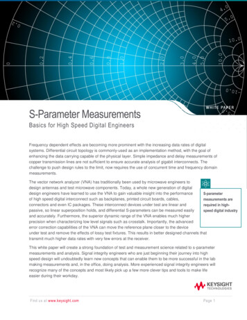
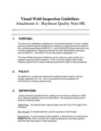
Vol-3 Issue-4 2017IJARIIE-ISSN (O)-2395-4396The Skoda MethodTPH 450 CEIIW – 0.42TPH 84.15 6. INSPECTION RESULTSNDT methods are used for inspection of pressure vessel. These methods are –DPT, MPT, UT RT. Inspection is doneby ASNT level II qualified person & according to procedure.Here the images for pressure vessels while inspecting vessel. Images includes before & after of weld parametersetting.i. Before weld parameter setting(A)( B)(C)(D)Fig.1.Inspection results of Ultrasonic Testing (A, B) & Liquid Penetrant Testing (C,D)ii. After weld parameter settingThe flow diagram for inspection of pressure vessel is as follows. According this inspection is carried out.6112www.ijariie.com1511
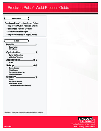
Vol-3 Issue-4 2017IJARIIE-ISSN (O)-2395-4396Fig.2. Inspection flow diagram for vessel(E)(F)Fig.3. Inspection results of UT (A) & MPI (B)7. ANALYSIS RESULTAnalysis of pressure vessel is divided into 3 analyses in which 1 stis related to overall pressure vessel & other 2 nd isfor weld zone. Above analysis includes 1) Temperature analysis 2) Structural analysis 3) Equilibrium or completeanalysisAmbient air temp.-22 CConvective heat transfer coeff. - 25 w/m2 CConductive heat transfer coeff. - 18 w/m Ci. Temperature analysis for welding1. At 190 AtFig.4. Temp.analysis at 190 61122.At250 Fig.5. Temp.analysis at 250 www.ijariie.com1512
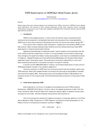
Vol-3 Issue-4 20173. at 300 IJARIIE-ISSN (O)-2395-43964. At 350 Fig.6.Temp.analysis at 300 Fig.7. Temp.analysis at 350 ii. Structural analysis for weldingThis analysis includesPressure tempSelf-weight of P.V.Calculating the value of Residual stress for preheats& post weld heating temp.At 190 At 250 Fig.8.Residual stressesat190 6112Fig.9.Residual stresses at 250 www.ijariie.com1513
Vol-3 Issue-4 20171. At 300 IJARIIE-ISSN (O)-2395-4396At 350 Fig.10.Residual stresses at 300 Fig.11.Residual stresses at 350 iii. Equilibrium or complete analysisFig.12.Total DeformationFig.13.Equivalent (Von-Mises)stress9. Result And DiscussionThe welding parameter of pressure vessel of ASTM 516 Gr 70 is to be changed due to invalid defects are observedduring inspection. For that we change that parameter by using analysis. When we reduced the bevel angle for 80 mmthick base metal the defects get reduced. The preheating & post weld heating shows that the value of residual stressare considerably get reduced .6112www.ijariie.com1514
Vol-3 Issue-4 2017IJARIIE-ISSN (O)-2395-4396Table -3 ResultNew P.V.ParameterOld P.V. DesignResultResultDesignBevel Preparation37.50Defect observedduring NDT testingSingle V300 CNo Defect observedduring NDT testingDouble VPreheat temp190 0 C366.6 MPa (max)250 0 C238.05 MPa (max)POWH temp250 0 C623.74 MPa (max)350 0 C498.7 MPa (max)9. CONCLUSIONIn above pressure vessels of ASTM A516 Gr 70 are to under study. The parameter of vessel i.e. bevel angle, preheat, post weld heat & NDT inspection stages are to set & checkedby using various inspection test.The defect are considerably get reduced or not goes to critical value after using that parameter.The analysis is to be done to vessel shows the temperature distribution over the vessel.The residual stress developed at preheat temp at 250 is less than residual stress developed at preheat temp190 . This caused reduction in defect formation.The residual stress developed at PWHT temp at 350 is less than residual stress developed at PWHT temp300 . This results stress relief into WZ, HAZ, BM.10.REFERENCES1) R. W. Hinton and R. K. Wiswesser, “Estimating Welding Preheat Requirements for Unknown Grades ofCarbon and Low Alloy Steels,” Welding Journal, vol. 87 (11), November 2008, pp. 273-278.2) Zhang Z, Ge P, Zhao GZ, Numerical studies of post weld heat treatment on residual stresses in welded impeller,International Journal of Pressure Vessels and Piping (2017), doi: 10.1016/j.ijpvp.2017.05.005.3) N. Yurioka, “Weldability of Modern High Strength Steels,” 1st U.S.-Japan Symposium. Advances in WeldingMetallurgy, 1190, pp. 79-100. Quoted as ref 8 in l-1.4) Siva Krishna Raparla, T.Seshaiah., Design And Analysis Of Multilayer HighPressure Vessels, IJERA, Vol. 2,Issue 1, Jan-Feb 2012, pp. 355-361.5) Luis D. Cozzolino et.al. “Investigation of post-weld rolling methods to reduce residual stress and distortion”Journal of Materials Processing Tech. 247 (2017) 243–2566) Mrs. SanapDeepali , Prof. Galhe D.S, Prof. Burkul R.M., A review paper on effect of welding speed and grooveangle on strength of butt weld joint using tig welding, IJESRT, may, 2015.7) Mohd Abdul Wahed, Mohammed Farhan., An Investigation of Non Destructive Testing Of Pressure Vessel,ISSN 2250-2459, Volume 3, Issue 1, January 2013.8) Oi Kenji , Murayama Masatoshi., Recent Trend of Welding Technology Development and Applications, JFETechnical Report NO.20 (Mar.2015).9) K. Satoh And M. Toyoda., Joint Strength Of Heavy Plates With Lower Strength Weld Metal, April 21-25, 1975.10) Apurva R. Pendbhaje et.al.Design And Analysis Of Pressure Vessel, ISSN:2321-1156 Volume 2, Number 3.11) Vijayesh Rathi, Hunny.,Analyzing the Effect of Parameters on SMAW Process, ISSN: 2278-9359 (Volume-4,Issue-6), June 2015.12) P. Kah and J. Martikainen., Current Trends In Welding Processes And Materials: Improve In Effectiveness,September 28, 2011.6
ASTM SA 516 Gr 70 P. R. Satpute.1, Prof. C.M.Gajare 2 1. PG Student , Department of Mech. Engg SVCET, Rajuri, Pune Maharashtra India 2 Associate Professor , Department of Mech. Engg KJ College of Engineering and Management Research, Pune,Maharashtra, India ABSTRACT The main objective this technical paper presents is design & development of weld parameter for pressure vessel. Pressure