Transcription
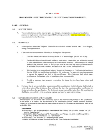
TOFD Examination of HDPE Butt Weld Fusion Joints.Carlos Correiacarloscorreya@gmail.com, Grupo Endalloy, www.endalloy.netAbstractPresent paper shows some relevant aspects to be considered when TOFD is required for HDPE Butt Fusion WeldedJoints examination. The influence of some relevant parameters as PCS, noise, frequency content, amplituderelationships of pulses and the use of water path wedges are addressed. Brief comparison between steel and HDPEapproaches are presented.1.IntroductionHDPE is a thermoplastic polymer, in other words, the material recover his properties aftercooling and can be subjected to considerable heating and cooling cycles without loose applicability.(1)HDPE is one of three major branches of Polyethylene (the other two are low and medium density PE) .Price, high corrosion resistance, easy manipulation, transportation and handling (HDPE is a verylight product), faster and easy welding process, flexibility and other characteristics have made HDPEpipes popular in industrial and domestic facilities.Applications like discharge of wastewater doesn’t require inspection even hydrostatic test. Butother industrial uses like transportation of water for mining processes, low and medium pressure gaslines, emergency fire systems and Class 3 nuclear piping systems, could require a considerable extensionof inspection. Classical Nondestructive Testing Methods as Radiography and Ultrasonic Shear Wavesangle beam doesn’t shows good results. The properties of this product makes difficult to work withshear waves since attenuation of this waves is an issue in this type of materials.In Article 4 of 2015 ASME BPVC Section V edition, the Ultrasonic Examination of fusion joints ofHDPE pipes has been included in the mandatory Appendix X.Volumetric evaluation of HDPE fusion butt joints can be performed with excellent results usingTOFD technique. Water path wedges has been introduced a few years ago by Olympus with markedlyimprovements increasing SNR, reducing attenuation and the dispersive effect of Rexolite over thefrequency content of the ultrasonic pulse. This combined effects allow production of high quality D-Scanimages.2.Probe Center Separation (PCS)Most codes ask for a minimum of variables to be considered during the TOFD proceduredevelopment. ASME BPVC 2015 Section V Article 4, ask for the classical parameters of table T-421 andothers showed at Table III-422 and Table X-421 related with specific aspect of inspection as instrumentmanufacturer and model, software employed, sizing method, scanning area, etc.One of the critical points related with inspection procedure, is the proper selection of the ProbeCenter Separation (PCS). The geometry of TOFD inspection, produces the following expression for thePCS as a function of refracted axis intersection (as shown in Figure 1): 2Where( )(Ec. 1)is the depth of the "intersection" point, and is the refracted angle.1
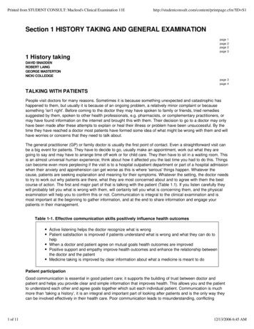
Figure 1. Classical TOFD arrangement.As the part thickness increases, additional setups must be included in order to properly isonify thematerial volume. ASME BPVC 2015 Section V Article 4 Appendix O, presents recommended number ofsetups as well as the " " values as a function of material thickness.It is important to consider that codes recommendation for volume coverage were developedusing steel as a material to be inspected. A classical approach for steel, for thickness ( ) less than 50mm, recommend , wherehave experimentally seen thatis the part thickness. For HDPE and thickness less than 50 mm, We as the intersection ultrasonic axis depth could result in betterimage definition, including discontinuities near the pipe surface. The situation is represented in Figure 2.During HDPE joint inspection, It seems a good recommendation to do some tests to best choice of toset the optimum PCS.Figure 2. TOFD PCS for3. (left) and Water Path WedgesWater path wedge is made as a conventional wedge but with a cylindrical hole water filled (orother fluid) trough convenient channels during scanning. Water wedges are an excellent choice since(2)attenuation of water is considerable inferior than attenuation in other conventional plastic materialsused for wedges (including Rexolite ). The use of water wedges increase the SNR, reducing attenuationand frequency dispersion associated with common wedge materials as can be seen in Table 1.Water path wedges with Teflon surface contact adaptor shows excellent performance overHDPE product surface. Figure 3 presents a water path wedge made by Olympus .Table 1. Attenuation in some related materials or mediums.Medium(3)WaterRexolite (7)(2)HDPEAttenuation [dB/mm]0.000870.320.3At a frequency2 MHz2.25 MHz2.25 MHz2
Figure 3. Water path wedges manufactured by Olympus (4)Water path wedges also reduce the problem of energy loss due to poor contact surfacematching area. The Teflon contact ring avoids fast water leak, reducing the quantity of water requiredduring the test. The water channel serves as a guide wave and assure that almost all UT beam makecontact with the pipe surface. Shear waves can t propagate in water medium reducing possible noisseand undesirable waves inside wedge material.The use of constant supplied water for inspection introduce positive effects related withmaterial temperature stabilization for inspection. Temperature changes produce velocity propagation(5)variations with associated sizing errors . Change of lateral wave position during one scan, due tovelocity changes, is common during field inspection of HDPE pipes when scanner crosses areas atdifferent temperatures induced by different Sun exposure.This type of wedges can have a drawback respect to high temperature applications or materialcorrosion related aspects not common found in HDPE pipes.4.Noise and Phase Observation.A typical HDPE TOFD A-Scan is presented in Figure 4, the A-Scan was acquired using a PCS 113mm, 6 mm diameter 2.25 MHz transducer and 60 degrees refracted longitudinal wave in 49 mmthickness HDPE with water path wedges. The Scan Plan can be seen in Figure 5. The equipment usedwas an Olympus OMNISCAN MX2 .One of the requirements of ASME BPVC Sec. V, Art. 4, App III (2015) is that the noise amplitudeshould not be superior to 10% FSH, an accepted noise range is 5-10 FSH. Figure 6 clear shows thatamplitude noise is below 8% FSH, in the worst case is SNR 9:1 (or 19 dB).The excellent SNR achieved produce a clear TOFD D-Scan image, as can be seen in Figure 7.Figure 4. A-Scan for TOFD configuration in 49 mm thick HDPE using a PCS 113 mm, 6 mm2.25 MHz diameter transducer.3
Figure 5. TOFD transducer position and beam intersection depth used for the A-Scan acquisition of Figure 4.Figure 6. Noise amplitude in the A-Scan. Lateral Wave followed by "noise" oscillations.Figure 7. TOFD image taken on HDPE 49 mm thickness sample including 5%, 75% and 50% depth and 25 mm lengthnotches and 75% thickness flat bottom hole (ordered from left to right).High SNR, help to analyze the phase relationships in the image signals which help todiscriminate the tips of the discontinuity (upper or lower tip) for sizing purposes.Figure 8 presents the B-Scan where a midwall notch is clear visible. The A-Scan including lateralwave and upper tip diffracted signal is presented. It is possible to observe that the approximated rule ofphase inversion relationship is satisfied by the two pulses. The lateral wave begins with “negative riseamplitude” while the indication pulse begins with a positive one. Backwall echo (strongly attenuated byID connected flaw) is in counter phase with lateral wave as predicted by theory.4
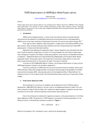
Figure 8. Phase relationships between lateral wave and the upper tip of an ID connected Notch.5.Frequency and Amplitude CharacteristicsThe dispersive nature of HDPE makes the peak frequency of the Lateral Wave considerableinferior to the peak frequency of the transducer but higher of the back wall echo peak frequency. Thisfact completely differs from steel inspection using Rexolite wedges. The lateral wave on steel usuallyhas markedly inferior frequency content compared to the back wall echo. The frequency content ofLateral and Back Wall Echo are presented in Figures 9 and Figure 10, respectively.Figure 9. Frequency content ofLateral Wave.Peak Frequency 0.98 MHzBandwidth 120%Pulse Width at -20dB 3.2 µsTransducer peak frequency 2.25MHz.5
Figure 10. Frequency content ofBack Wall Echo.Peak Frequency 0.59 MHzBandwidth 85.7%Pulse Width at -20dB could notbe well established since signal issaturated. Transducer peakfrequency 2.25 MHz.Mode converted echo in HDPE exhibit a very low amplitude, even less than lateral wave, whichis a relevant difference from steel situation. Shear wave is strongly attenuated in HDPE this produce alow amplitude mode converted echo in HDPE. In high thickness pipe, the mode converted echo couldpass unseen. Figure 11 shows the mode converted amplitude compared to Lateral Wave and Back WallEcho.Figure 11. Low amplitude mode converted echo could be seen at the end of the A-Scan.Since Mode Converted region could not be useful (a difference with steel case), the range couldbe selected just to include the lateral wave and Back Wall Echo, including 1 to 3 µs before the lateralwave and a the complete waveform of back wall echo. Most part of times weld discontinuities lies inthe vertical plane between two transducers and no defects are expected beyond the fusion zone, so inany case mode converted information is not as relevant as in steel.6.Dead ZonesAs in all TOFD conventional applications a considerable surface dead zone could be an issue.HDPE also presents the same drawback. A conservative approach to estimate the surface dead zone ((6)) could be calculated with the following equation :6
(Ec. 2)Where:: Longitudinal wave velocity: Lateral wave pulse length at -20 dB: Half the distance between the index point of two transducersUsing the values related with the acquisition of B-Scan of Figure 7, 2.4 1.7, 56.5,, the surface dead zone is: 15The back wall dead zone (.(6)) can be estimated using the equation :/ ( ) (Eq. 3)Where:: time of flight of back wall echo: Thickness of the pieceUsing the previous values andback wall dead zone is: 62, measured in the A-Scan (or by Pythagoras). The 2.5Figure 12, shows that upper tip of 75% notch height could be seen in close proximity with theactual upper dead zone (although the notch tip is 3 mm inside theoretical dead zone), diffraction arcscan assist the interpreter to confirm the detection.Figure 12. Upper tip of 37 mm height notch (75% of thickness). The upper tip could be detected despite is beyondthe theoretical upper “dead” zone.Figure 13 show the measurement cursor at 15 mm, the calculated theoretical depth of surfacedead zone and the tip of the notch which is close to 12 mm depth ( 3 mm inside this zone).Calculations using equations (2) and (3) seems some conservative. A better option could beexperimentally size this “dead” zones using notches in a reference block.7
The ESBEAMTOOL 5 shows different values from those calculated using the above expressions(2) and (3), as shown in Figure 5. The reason could be the theoreticalvalue software uses.Figure 13. Calculated Surface Dead Zone and a upper tip notch signal inside this zone.7.Image AnalysisTOFD images of HDPE Fusion Butt Welds with water wedges, usually are acceptable withreasonable low noise and seems doesn’t present many difficulties to be analyzed. Strategy for analysiscould be: Explore the lateral wave amplitude and frequency contentWhen a variation in coupling exists, the variation of the lateral wave amplitude shall becorrelated with variation in back wall echo and mode converted echo amplitude (if mode converted isobserved). Suddenly variations, most cases reduction or in apparent augmentation of lateral waveamplitude without variation of other pulses usually is an indication that there exist the possibility that adiscontinuity is present associated to the upper region. This situation is presented in Figure 14.Figure 14. Variation of the lateral wave amplitude, bandwidth and peak frequency. (left) unflawed zone, (right)flawed zone. Explore the back wall echo amplitude variationA reduction of the amplitude of the back wall echo usually means something happen at this region,small reduction even. A reduction of amplitude accompanied with a change of contour also means adiscontinuity is present. As can be seen Figure 15.8
Figure 15. Change in the amplitude and contour of back wall echo. Explore the coincidence of upper indications and back wall echo amplitude variationsIt is very important to see if changes in the back wall eco are synchronized with changes in theupper region of the image, this could be the upper tip of an ID connected discontinuity. If the image isnot carefully analyzed the tips of a high height discontinuity could be interpreted as isolated indications,as shows Figure 16, a supplementary UT technique as Phased Arrays could clarify the situation.(8)To increase the POD, Phased Array could be applied with water wedges and longitudinal waves .Figure 16. Superposition of notches over D-Scan image.8.Image processingImage processing is generally applied over TOFD images. Figure 17 shows the most common techniquesapplied to enhance the indication patterns.9
Original unprocessed image.Lateral wave synchronization. Make easier toidentify indications close to the upper deadzone.Lateral Wave Removal help to confirm thepresence of indications in close proximity withlateral wave.SAFT processing makes clear the presence ofID open flaws, vanishing the "hyperbolic" arcsat flaw extremities.Figure 17. Classical image processing applied over TOFD images.Image processing shall be carefully applied. It is possible to partially delete actual information comingfrom real flaws using some algorithms as Lateral Wave Removal. Indications in the upper zone could beaccidentally deleted or strongly attenuated in the process.10 page
ASME BPVC 2015 Section V Article 4, ask for the classical parameters of table T-421 and others showed at Table III-422 and Table X-421 related with specific aspect of inspection as instrument manufacturer and model, software employed, sizing method, scanning area, etc. One of the critical points related with inspection procedure, is the proper selection of the Probe Center Separation (PCS .