Transcription
Weld Design andSpecificationJim Glancey, PEDepts. of Bioresources Engineering& Mechanical EngineeringUniversity of Delawarejglancey@udel.eduhttp://udel.edu/ jglanceyI can’t explain everything . . .1000 ft4 in6 in1/4”Inside weld entire length1
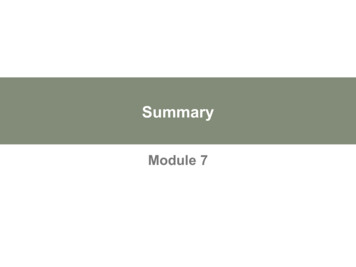
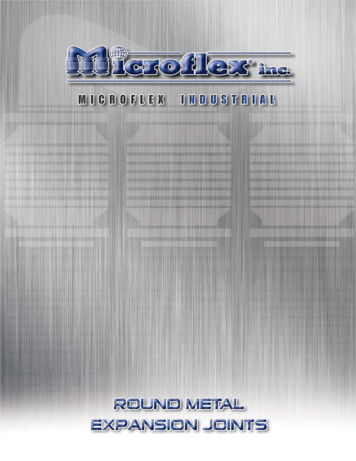
Factors in Weld DesignI Strength (static and/or fatigue)I Material and the effects of heatingI CostI DistortionI Residual StressesI Easy to WeldStatic StrengthI Stress- strain diagramFAStress (σ) FAStrain (ε) Lultimate(tensile)yield LLF2
Shear StrengthI Ingeneral, material fails in shear due todistortion (at a molecular level)I Criteria for failure: Ductile: Shear Strength 0.5 Tensile Strength Brittle: Shear Strength 0.75 Tensile StrengthI Weldstrength analysis is generally based onShear Strength3
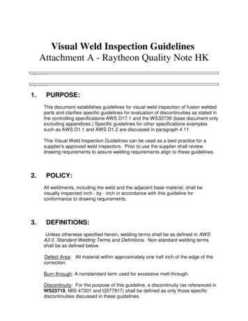
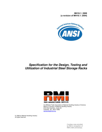
Static Strength of WeldsButtFNormal F1/875oFilletShear 3/81/42FFw*hFw*hFFMax Normal 0.618w * hFMax Shear F0.707w * hh throat size!Weld Size vs. Throat SizeButth plate thickness weld size1/875oFillet3/81/4h 0.707 * plate thickness0.707 * weld size4
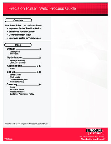
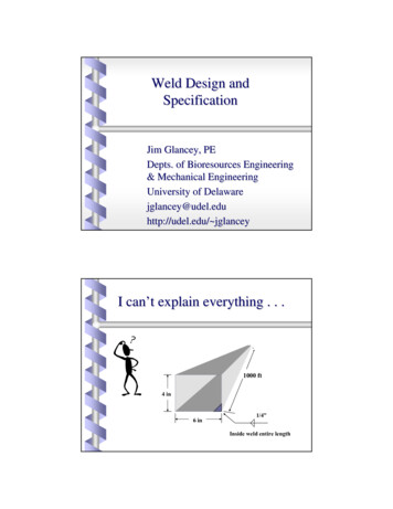
Fatigue StrengthStatic Tensile Cycle1000InfiniteLife1,000,000Cycles of Loading5
Endurance LimitI For Steel: Endurance Limit 0.5 * Tensile Strengthor 100 kpsi, which ever is lower.I For Aluminum: No endurance limit (cannot have an infinitelife)6
Factors for Fatigue Stress AnalysisType of WeldStress IncreaseButt Weld1.2Transverse Fillet1.5Parallel Fillet2.7T-butt with corners2.07
Strength ConsiderationsI Tryto minimize the stresses in welds; makethe parent materials carry highest stresses.I Butt welds are the most efficientI Avoid stress concentrationsI Intermittent weld length should be at least 4times the fillet sizeI Minimize weld size to reduce potential forfatigue failure8
Effects of Welding on MetallurgyI Depends on the alloy and welding processI In general, cracking is promoted by: stress concentrations brittle parent material after welding (lowcarbon steels) hydrogen in the weld metal impurities in the weld metal9
Reducing DistortionI PreventoverweldingI Intermittent weldingI Minimize number of passesI Place welds near the neutral axis of the partI Balance welds around the neutral axisI Anticipate shrinkage forcesI Residual stress relief10
Neutral AxisI The line (plane) where bending stresses arezero.11
12
13
Factors in Weld Design IStrength (static and/or fatigue) IMaterial and the effects of heating ICost IDistortion IResidual Stresses IEasy to Weld Static Strength IStress - strain diagram Strain (ε) Stress (σ) F A L L yield ultimate (tensile) F F A L. 3 Shear Strength IIn general, material fails in shear due to distortion (at a molecular level) ICriteria for failure: Ductile: Shear .