Transcription
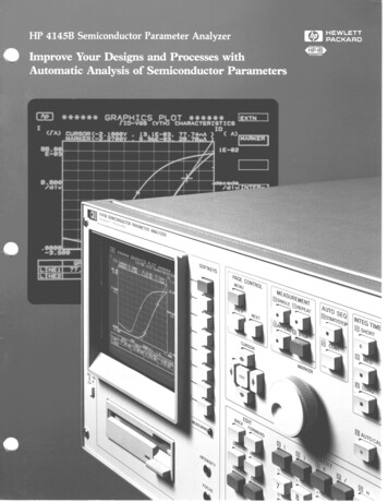
Improvi! Your Device QualityThe HP 4145B performs fast, accurate analysis ofsemiconductor devices to increase your productivityand improve your device quality. You can stimulateand measure voltage and current sensitive deviceseasily with the four Source Monitor Units (SMUs).And to help you analyze data, the HP 4145Bcomputes dc parameters like h,, and gm for you.The HP 4145B’s versatile SMU-based architecturesaves you valuable time and eliminates measurementinstabilities caused by changing DUT connnections.Each SMU can alternately act as a voltage source/current monitor or current source/voltage monitor.You can characterize a four-terminaldevice completely without changing device connections simply change the SMU’s current/voltageoperating mode.Shorten Your Design andAnalysis TimesThe HP 4145B automates tedious data gatheringduring device characterization. When designchanges are made, you can evaluate them quicklyand efficiently, minimizing project delays andcost overruns.At the touch of a button, the HP 4145B canposition cursors and lines on the display, giving youdirect readout of dc parameters like Early voltageand threshold voltage. You can position a markeranywhere on the curve and read out coordinatesdirectly. Or zero in fast with “auto scale”, “zoom”and “move window“ commands.Increase Productivity on the Benchor in a SystemYou can produce results from the start with theHP 4145B. Use the powerful front panel keys forcontrol and analysis in stand-alone bench-topapplications. Or use the HP 4145B’s AutoSequence Programming to control measurements,data storage, and plotting functions without usinga computer. And, since the HP 4145B is completelyprogrammable, you can easily incorporate it into anautomatic test system to increase your testthroughput.HP 4145B Key Performance FeaturesSource Monitor Unit (SMU)Voltage Monitor (VM)The HP 4145B provides you with four SMUs. EachSMU can be used as a voltage source/current monitor oras a current source/voltage monitor.Two voltage monitors are built into theHP 4145B in addition to the SMUs.Measuring Ranges: O.OOOVdc and 2.0000 VdcAccuracy: rtO.S% (2OV range) and20.2% (2V range)Resolution: 1 mV (2OV range) and lOO p V (2V range)SMU Range:V: 33 mVdc to 1!1100.00 VdcI: 1 pAdc to klOO.0 mAdc(3 50 fA resolution in current monitormode)Accuracy:V: 0.15% to -1-(0.15% 40 mV)I: 50.4% to 1.8%Voltage Source (VS)Measurement SpeedMake up to 150 measurementsper second.Two voltage sources are available in additionto the SMUs.Output Range: 2O.OOO VdcAccuracy: fOS%
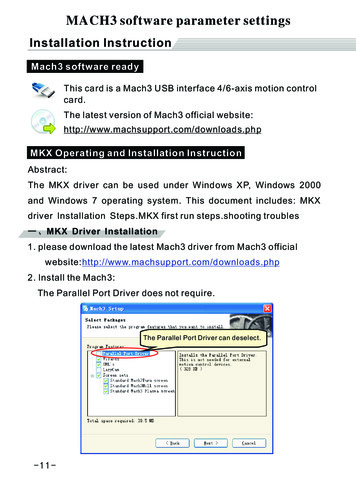
Completely Evaluate Your Semiconductor DevicesBipolar TransistorsMOS structures, Junction FETs, GaAs FETslSemiconductor DiodeslPhotoelectric conversion devices (Photodiodes,Phototransistors)lLight Emitting Devices (LEDs, GaAs InfraredEmitting Diodes)lOperational AmplifierslGated Diodes0 Static Electricity Induced Transistors (SITS)The HP 4145B excels in both TEG (Test ElementGroup) measurements performed on semiconductorwafers and in parameter extraction of simulationmodels in computer-aided design applications. Youcan also use the HP 4145B to characterize packageddevices with the supplied HP 16058A Test Fixture.Applications include dc characterization of thesesemiconductors:llEasily Characterize Both Wafers and Packaged DevicesMOS Structure Parameter AnalysisTheoretical threshold voltage is a dc parameterof great significance. The HP 4145B reduces thetime required to obtain this parameter. The example CRT display shows FET & - VGS andlog ID - VGSon a plot with double Y axes.Using the do - Vos plot and LINE function, you canread theoretical VGS(th) (X-intercept) as2.40 volts. ID&h)is also read directly (marker readout)as 6.243 PA. You can perform this completemeasurement and graphic analysis in less than twominutes.Use the log ID - Vos plot to obtain Vos values atspecific values of ID. You can read Vos valuesin numeric form with the HP 4145B’s marker andinterpolation functions.Parameters which can be analyzed include:lThreshold Voltage Bulk Potential Dependency0 Extrapolated Threshold VoltagelGain Factor (K) in Saturated/Non-SaturatedRegionslMutual Conductance Drain and Gate VoltageDependencyllllBody Factor Effect MultiplicationFactor (M)Punch-ThroughVoltagePN Junction Break-Down VoltageChannel Conductance-GateVoltageCharacteristicsDirect Readout of Threshold Voltage Speeds MOS Analysis
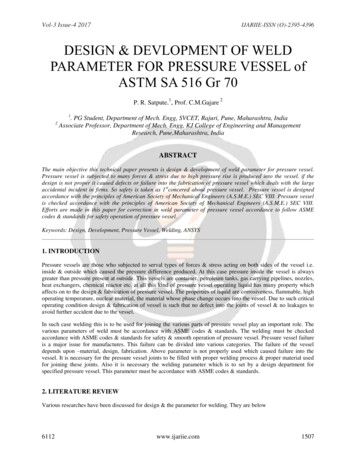
Increase Your Efficiency DuringResearch and Development of New MaterialsThe HP 41458 provides your research lab withcapabilities that will meet dc characterizationrequirements for present devices, and alsoprovides you with functions needed fordevelopment of new materials.The HP 4145B features eight different analysismethods. You can make readings using contactline,gradient, comparison, zoom and marker methods.The calculation function has 11 arithmeticfunctions including LOG, EXP and A (differentialcalculation). You can also use two user-definedfunctions.New materials which can be analyzed include:lGallium Arsenide DeviceslLiquid Crystal StructureslCeramic SemiconductorslAmorphous Silicon DeviceslSolar Cell ElementslSolar Cell ArraysBipolar Device Parameter AnalysisThe HP 4145B is a valuable tool in bipolarintegrated circuit design. You can simultaneouslymeasure Ic - VBE and Ie - VBE . After eachmeasurement, the HP 4145B automaticallyCOmpUteSand plots hfE vs. Ic on a log-log scale.Quickly Extract Parameters for the Gummel-Poon ModelTo analyze this data, you can position a straightline tangent to any point along the hFE - Ic curve.Once the line is positioned, you .can read slope andX intercept values directly on the CRT. Next, byperforming a parallel shift on the tangent line, youcan obtain numeric values of knee current (1 ) andmaximum value of hFe @FM) directly on the CRT.These are parameters of the Gummel-Poon Model.Parameters which can be analyzed include:lDC Current Gain (hfs, hfa) - COlleCtOrCUrrentCharacteristicslEvaluation of Surface Recombination Currentas Related to PN Junction Forward BiasCharacteristicslEvaluation of Current Generation as Related toPN Junction Reverse Bias Characteristics* Breakdown Voltage (BVEBO,BVCBO, BVCEO,BVcso )lSheet ResistancelResistivitylCollector-Emitterand Emitter-BaseSaturation VoltagelCollector Cut-Orf Current (1 0, 1 130)7
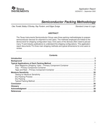
Automate Your Bench-Top Evaluation ProceduresYou can program the HP 4145B to performsequential measurements and output the results.The AUTO SEQUENCE SETUP (shown at the right)is an automated procedure for characterization ofIc, Is-VBE, hFe-Ic, COlleCtOrCUrriM-VOkageand VCE(SAT)of a bipolar transistor. [, ]** AUTO123The auto sequence program initiates a measurement sequence, activates the plotter/printerfor hardcopy results and then stores measurement data indisc memory. Hard copy output is shown below.GRAPHICSME-ItPLOTI*** *CHARACTERlST*CS ,‘fab’d.,I.,I) .-Upg:::7891011121314151617100, 100.3500.3500PLOTGET P NPNlSINGLEPAUSEPLOT 3600.3600.7000,7000GET P VCESATSINGLEPLOT 3600. 100,7000.3500PAGEWAIT 60PAINT**it.***ISET3UP ** Call up program from discSingle Sweep-Output CRT display contentsbEF\; “;; ;:,“I,,o” discAllowsbeforeviewing of resultsoutput to plotterAdvance plotter pageWait time before executionnext commandGRAPHICSPLOT******“CESAT-IC CHARACTERrSTtCS‘cy .t“,w”lDDY““YSEQUENCEGET P ICBVBESINGLEPLOT100.3600.3500.7000IIIII1Store Your Programs and Data on Flexible DiscsThe HP 4145B uses double-sided, double-densitymicrofloppy discs to store measurement data andprograms. The furnished system disc contains theHP 4145B’s operating system. Load the operatingsystem into memory at power-on, then use anyinitialized disc to store your data. You caninitialize discs and copy the operating systemwith the HP 4145B or an HP 9000 Series 200/300computer.Use any standard HP 3.5 inch disc such as theHP 9219214. Each disc stores up to 630 Kbytesof information. Store approximately 240 programsor 105 data files on a single disc.Analyze Your Data with an HP 9000Series 200/300Computerof
Select From Five Different Display Modes to Suit Your Evaluation PurposeYou can use the Schmoo Plot for map-type displayswhen analyzing characteristics affected by twoindependent variables. Each characteristic value isrepresented by one of five different symbols. Youcan highlight a single symbol and display itsnumeric value with the cursor.The Matrix Display is a numeric display of acharacteristic affected by two variable parameters.Rows are formed by up to 1024 VAR 1 values.Columns are formed by up to 6 VAR 2 values.Matrix elements can be measured values or functionsof VAR 1 and VAR 2.User Functions Can Calculate h,, fand 1 I, e hV/KT)BThe HP 4145B provides you with two UserFunctions in which II front-panel arithmetic operators may be used. Values of User Functions arecomputed simultaneous with each measurement anddisplayed in the same manner as a measurementvalue.The most common constants used in semiconductor analysis are also available on front-panel(K: Boltzmann constant; q: electron charge;e: dielectric constant of a vacuum).The List Display shows you all measurement conditions, values and calculations in a list format.You can analyze semiconductor parameters changingas a function of time in the Time Domain.Make measurements up to 85 minutes witha minimum interval of 10 ms. Use the graphic,matrix or list display modes.Use the Graphic Display for simultaneousdisplay of two characteristics using double-axisformat. The Graphic Display gives you a quickgrasp of overall device *I*CHARACTERISTICSy-, ,-lIC( A)CUR5Off(-.430RVt35.66nA,35.&d:"()1E 00A)lE 0/d.v( W
Easy-To-Use Menu and Page FormatFill-in-the-BlankThe PREV, NEXT and MENU keys make operationas simple as turning the pages of a book. Measurement setup can also be controlled by operating theSOFTKEYS.To program measurement setups simply keydata into the blanks indicated by the display pointer(b). After your program is completed, you can storeit on the disc.Eight Functions Give You CompleteAnalysis of Test ResultsMarker gives digital readout anywhere on curve.Cursor gives numeric readout anywhere on CRT.Line shows direct readout of slope (gradient)plus X and Y intercepts.Line Control changes line position.Auto Retrieve displays measurement data in adifferent format.STORE and RECALL provide comparisonfunctions using an Overlay Display or DoubleAxis format.Auto Scale optimizes graphic scaling.Zoom Function expands or contracts the graphicsplot.SMUs (Source MonitorProgramming******.-GRAPHICSPLOT *******XC-“CE CHARAtTERISTICSUnits) Provide Reliable MeasurementsWith the HP 4145B’s SMU architecture, you canmake a complete set of dc semiconductor wafermeasurements with one probing. This eliminatesinstabilities caused by changing connections at theDUT and adds up to highly reliable measurements.The accompanying diagram shows four SMUsconnected to a Field-Effect-Transistor(FET). In adrain current vs. drain voltage characteristicsmeasurement, you set all SMUs in the voltagesource/current monitor mode, SMUl and SMU2operate as swept voltage sources. SMU2 monitorsdrain current. After completing this test, you canmeasure breakdown voltage. Simply change SMU2to operate as a current source/voltage monitor andmeasure the breakdown voltage at the desired constant current.Selected area of“ZOOMED”toresolution.Alsofunction is useda curve isincreaseLINEfor analysis.
System Expansion is Easy with HP-IBresolution. And the HP 4140B pA Meter gives youcurrent resolution down to 1 fA.The HP 4145B easily interfaces with other instrumentationand controllers to construct a processevaluation system that best suits your needs. Theaccompanying diagram shows a complete semiconductor evaluation system.The powerful HP 9000 Series 300 TechnicalComputer controls the system. You can make highquality plots with the plotter including direct dumosIdf the HI’ 4145B’s display.You can combine the HP 4145B and HP 4085MSwitching Matrix to make 1 pA and 1 mV resolutionmeasurements at any of 48 DUT pins. Add theHP 4280A 1 MHz C Meter/C-V Plotter to makeC-V and C-t measurements with 1 fF capacitancePlotterHP-IB is an implementationANSI-MC 1.1 standards.of IEEE-488 andHP 41408 pA Meter/DC VoltageSourceHP 4280A1 MHz C Meter/C-V PlottercHP 9000 SeriesComputer300HPExpand erAnalyzerCapabilities with this bemiconductor parameter fvatuationMeasure Wafers and PackagedYou can connect the HP 4145B to a wafer proberand test devices in the wafer stage. After adevice is packaged, use the supplied HP 16058Atest fixture. The HP 16058A includes seven plugin test modules for testing many different packages.Shown here are the HP 16058A Test Fixture plusa supplied connector plate for adapting to probershield boxes.11system
SpecificationsMEASUREMENTSource MonitorEachmonitorvoltage.sourcingSMUVariable1: Variable1 can be swept linearlyor logarithmically.Linear sweepis a staircaseoutputof voltageor current.Sweep parametersincludeSTART,STOP and STEP levels.Theseparameterscan be variedby the user.Log sweepis also a staircase,but at 10, 25 or 50 points perdecade.The maximumnumberof data pointsis limitedto 1024 for a single VAR 1 sweepor 1140 for a multiplesweep.Time domainsweep is accessedwhen VAR 1 is not assigneda sourcefunction.An initial WAIT time and a time intervalare specified.Wait time is specifiedup to 100s with resolution of 10 ms. Measurementintervalis specifiedup to 10swith resolutionof 10 ms. Maximumnumberof data pointsis 1024.Variable2: Variable2 sweepis a staircasewith specifiednumberof steps. Variable2 is incrementedafter completionof eachVAR 1 sweep.SynchronouslyVariable(VAR 1’): VAR 1’ outputprovidesa sweep synchronouswith VAR 1 but at outputlevelsproportionalto a fixed ratio or offset relativeto VAR 1.The ratio is definedas VAR 1’ a x VAR 1, where ais a fixed ratio of kO.01 to *lo. An offset is definedasVAR 1’ b VAR 1, whereb is any value that will not causeVAR 1’ to exceedthe maximumallowablesourcecurrentor voltagecompliance.Hold Time:Hold time is definedas the delay from application of initial outputlevel to start of the first delay time.See Figure1. Hold time can be varied from 0 to 650sf (0.5% 9 ms) with 10 ms resolution.Delay Time:Delay time is definedas the delay time fromapplicationof step outputlevel to start of measurement.See Figure1. Delay time can be set from 0 to 6.5s k(0.1% 5 x N’ ms) with 1 ms maximumresolution.l N: numberof monitorchannels.Unit (SMU) CharacteristicsSMU can be programmedto sourcevoltageandcurrent,or converselyto sourcecurrentand monitorTables1 and 2 specifyboth the measuringandparameters.Each SMU canvoltageat 0 volts“ReferenceData”on SMUs.also be programmedto COM mode.This setsand currentcompliancelimit at 105 mA. Seesectionon page 13 for more informationoutput/measurementdc current 4 digits.resolution:SeeTablesdc volts 4-l/22 for details.1 andVoltagemeasurementinput resistance/currentresistance: 1012flVoltagesourceoutputresistance/currentinput resistance:0.4R.Maximumcapacitiveload: 1000 pFTableSMU tionand Accuracy 1*IoUt is SMUoutputcurrentSMU Currentin amps.Table 2Range, Resolution1and AccuracyFigure\DELAY Time’HOLD Tikoutput voltage in volts.fA resolutionin current monitor mode.1. Accuracyspecificationsare given es k % of reading whenmeasuringor i- % of setting when sourcing.2. Accuracytolerancesare specified at 23’C 5”C, after a 40minute warm-uptime. with AUTO CAL on, and specified at therear panel connectorterminalsreferencedto SMU common.Tolerancesare doubled for the extendedtemperaturerange of10 C to 4ooc.3 Maximumcurrent when SMUs are sourcingvoltage.4. Maximumvoltage compliancewhen SMUs are sourcingcurrent.1. SweepSequence\3JINTEG Tome‘Vout IS SMU“50No. of STEPS’tSweep StarttSweep EndNote: *Settmg ValueVoltage Sources (VS) MUVoltage/CurrentComplianceLimit:voltageand currentresolutionare the same aslisted in Table 1 and Table 2. An exceptionis that maximumcompliancecurrentresolutionis 50 pA.Compliancevoltageaccuracyis the same as listed in Table 1.Compliancecurrentaccuracyis i- (1% of range 10 pAI. 0.2nload:1000pFComplianceVoltage/CurrentSweep CharacteristicsEach SMU sourcecan be sweptVariable2 (VAR 2) or SynchronouslyTable3VS Voltage Output RangeAlso see “ReferenceData” sectionOutput VoltageRange- 2ovusing Variable1 (VAR 1).Variable(VAR 1’) mode.12Resolution1 mVAccuracy*(OS% of setting 10 mV)Max. OutputCurrent10 mAJ
Voltage MonitorsInputresistance:Cursor:In the GraphicsDisplayMode the coordinatesof theintersectionof moveableverticaland horizontallines isdisplayed.A cursoris availablefor both X-Y1 and X-Y2graphs.In the List and MatrixDisplays,a flashingarrowindicatesa selectedrow of data. In the SchmooDisplay,the Z-axisvalue of the intensifiedsymbolis displayed.Auto Scale:In the GraphicsDisplayMode, X and Y scalefactorsare automaticallyadjustedto yield optimumdisplayof measureddata.Zoom Function(- - - - I 1): In the GraphicsDisplayMode,the ZOOMfunctionexpandsby two or contractsto l/2 thearea surroundingthe cursor.Line: In the GraphicsDisplayMode, two variableslope linescan be displayed.Theselines can be used as tangentstodetermineslope and X and Y interceptsof dc characteristicscurves.Move Window:In the GraphicsDisplayMode, the MOVEWINDOWcentersthe displayaroundthe cursor.Characteristics(VM)1 MR i1% paralleledby 100 pF f 10%Table 4VM Voltage MeasurementRangeAlso see “ReferenceData” sectionMeasurementVoltage RangeResolution100 /Iv1 mV* 2vf20VAccuracyk (0.5% of readingk (0.2% of reading 10 mV) 10 mV)Shared Characteristicsof SMU, VS and VMMaximumallowableterminalvoltage:1OOV peak acrossSMUand VM input terminalsor SMU and Vs outputterminals,or betweenthose terminalsand guard: and 42V maximumfrom Commonto solution:mm(6 inch)116 mm2048diagonal(4.6 inches)x 2048General SpecificationsCRT.x 92 mmSelf-Test Function:(3.6 inches).points.ExternalCRT AnalogOutput:X, Y and Z outputsof 0 to1 Vdc into 3300 for X and Y, and 24Ofl for Z output,are availableat rear panel BNC connectors.OperatingTemperaturePower Requirements:Micro FlexibleDisc: 630k byte, doubleAvailableUser Records:2432File Sizes:MeasurementSetup:MeasurementData plus Setup:Auto SequenceProgram:OperatingSystem:sided,double612 mm(24.1426 mmin)DCalculationwith7 digitresolutioni 10s;240v- I 0% 5%;(16.75in)Wx 235 mm(9.06in)HxReference DataReferencecalculations20/22ov27 kg (59 Ibs) approximatelyfor HP 4145A mainframe.33 kg (73 Ibs) includesmainframeand furnishedaccessories.Source Monitordoes100/ito 40 c; 70% YSISThe HP 41458displays5 digits. IO”C48 to 66 Hz; 270 VA max.densityDimensions:5234254Range:RH at 4O”C, ture29 C.DATA STORAGELdWhen poweris turnedON, the HP 4145Esequencesthrougha self-testthat verifiesstatus of major functionalblocks.Self-testcanvia HP-IB or via keyboardoperation.automaticallyoperationalbe actuateddataare typicalvaluesgivenforinformationpurposes.Unit (SMU)MeasurementTime:Measurementtime responsetime rangin!time integrationtime.SMU responsetimeincludessetup and settlingtime plus waittime. Wait time is microprocessorcontrolledand dependenton currentrange, as shownin Table 5.Table 5SMU Response TimeandConstantsAvailableon the Keyboard:Keyboardconstantsare storedin memoryas follows:q: Electroncharge(1.602189x lo-19 Coulomb)k: Boltzmann’sConstant(1.380662x lo-23 J/OK)e: Dielectricconstantof a vacuum(8.854185x lo-12 F/m)The followingunit symbolsare alsoavailableonthe nge100 nA to 100 mA1 nA and 10 nAAnalysis Functions:Setup/Settling2.7 ms2.7 mstimeSMU Wait Time0.2 ms47.5 msRangingtime is dependenton numberof rangesrequiredduringmeasurement.Lower rangesrequiremore rangingtime than the higher ranges.R
HP 4145B. Use the powerful front panel keys for control and analysis in stand-alone bench-top applications. Or use the HP 4145B’s Auto Sequence Programming to control measurements, data storage, and plotting functions without using a compute