Transcription
Visual Weld Inspection GuidelinesAttachment A - Raytheon Quality Note HKhttp://sites1.it.ray .com/metalfab/images/Red line.GIFhttp://sites1.it.ray .com/metalfab/images/Red line.GIF1.PURPOSE:This document establishes guidelines for visual weld inspection of fusion weldedparts and clarifies specific guidelines for evaluation of discontinuities as stated inthe controlling specifications AWS D17.1 and the WS33739 (base document onlyexcluding appendices.) Specific guidelines for other specifications examplessuch as AWS D1.1 and AWS D1.2 are discussed in paragraph 4.11.This Visual Weld Inspection Guidelines can be used as a best practice for asupplier's approved weld inspectors. Prior to use the supplier shall reviewdrawing requirements to assure welding requirements align to these guidelines.2.POLICY:All weldments, including the weld and the adjacent base material, shall bevisually inspected inch - by - inch in accordance with this guideline forconformance to drawing requirements.3.DEFINITIONS:Unless otherwise specified herein, welding terms shall be as defined in AWSA3.0, Standard Welding Terms and Definitions. Non-standard welding termsshall be as defined below.Defect Area: All material within approximately one half inch of the edge of thecorrection.Burn through: A nonstandard term used for excessive melt-through.Discontinuity: For the purpose of this guideline, a discontinuity (as referenced inWS23719, MIS-47201 and G577917) shall be defined as only those specificdiscontinuities discussed in these guidelines.
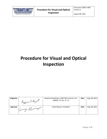
Double fillet weld: A fillet weld in a T joint configuration with weld on both sidesof the abutting member.Effective weld length: The effective weld length shall be only that portion of weldthat is full size and has proper fusion. (See paragraph 5.8)Inclusion: For clarification, an inclusion, as defined in AWS A3.0, is entrappedforeign solid material, such as slag, flux, tungsten, or oxide.Single fillet weld: A fillet weld in a T joint configuration with weld on one side ofthe abutting member only.Incipient Melting: A condition, in the base material heat affected zone which mayexist at or near the toe of the weld in which an inter-metallic phase of the basematerial is beginning to or is on the verge of melting; a textured or mottledsurface results.Arc Erosion: A nonstandard welding term that describes a condition caused byan arc impinging on the base material adjacent to be weld. The condition resultsin a surface roughening of the base material.Linear Discontinuities: A discontinuity with a length that is substantially greaterthan its width and includes cracks, incomplete fusion, overlap, and incompletepenetration.Design Configuration Verification: Verifying that the size, length andlocation of each weld on the part is as specified on the engineering drawing andthat no unspecified welds have been added.4. GENERAL REQUIREMENTS: Any units that fail to meet therequirements of this Guideline shall be rejected and documented.4.1 Raytheon Quality Note (RQN) HK contains welding requirements not listedon Raytheon's drawings. All suppliers and visual weld inspectors shall beapproved in accordance with RQN HK.4.2All weldments shall be inspected inch-by-inch to the print requirements.Specifically, the size, length and location of each weld required by the print shallbe verified on the part and no unspecified welds have been added.Uniform bead appearanceExcellent weld workmanship is easilyinspected and acceptedNon-uniform bead appearancePoor workmanship requires more inspectiontime and increased chance of rejection
4.3Engineering Hotline 978-470-6300 - Suppliers can utilize Raytheon'sEngineering Hotline as a central point of contact for all related welding issues,specifically questions related to the Technical Data Package (TDP) and visualweld inspection questions. A Raytheon Weld Subject Matter Expert (SME) willrespond to your questions in a timely manner and provide technical support asneeded. Raytheon Weld SME’s, Engineering, Supply Chain, and Quality staffuse the hotline database to coordinate on all supplier issues and improvesupplier performance.4.4Raytheon's approved weld inspector shall document weld inspectionresults using the Visual Weld Inspection Checklist, Figure 1. The Visual WeldInspection Checklist is recommended as a best practice for supplier's approvedweld inspectors.4.5The inspectors’ tool kit shall include, as a minimum, the following tools:VISUAL WELD INSPECTORS TOOL KITTOOLFlashlightFillet Weld GagesTOOL REQUIREMENTXenon or Krypton bulbStandard G.A.L. Fillet weld GagesUndercut GagesGo, No-Go burr type6” Scale12 Foot Tape Measure1/64 inch incrementsRECOMMENDED2AA or 2AAA size batteriesSizes -0.010”, 0.015”, 0.020”,0.025”, 0.035”, 0.050, 0.060 and0.0705x glass simple lensMagnifying Lens10x glass simple lensMetal ScribePin GagesDividers, Caliper,Micrometer1/64, 1/32, 3/64, 1/16, 3/32NOTE:For tool and gage selection, decimals and fractions can be interchangedfor example a fillet weld size of 0.12 can be inspected with a 1/8-fillet weld gage.4.6Visual weld inspections shall be conducted with the unaided eye. Oncethe initial assessment has been made with the unaided eye and a suspectarea is identified, magnification may be used to determine acceptability.
4.6.1 Magnification, when used, shall be done using only approvedlenses as included in the inspector’s tool kit.4.6.2 Initial use of magnification shall be with 5x.4.6.3 When acceptability or rejectability cannot be established with 5xmagnification, use 10x magnification and consult supervision ifrequired.4.7Visual weld inspections shall be conducted under proper lightingconditions.4.7.1 All weld areas shall be illuminated with an approved flashlight asincluded in the inspectors tool kit.4.7.2 Welds that will be covered or obstructed by subsequent operationsshall be inspected prior to the subsequent operations.4.8Visual weld inspections shall be completed after all operations areperformed on the weldment that may cause additional stress build-up inthe part and may cause cracking. This includes all straighteningoperations.4.9The initial angle of viewing for each weld shall be approximately 90 /45 to the weld face. Other viewing angles may be used to closelyscrutinize specific discontinuities.4.10For direct visual inspection, eye to work piece distance shall not exceed24 inches.4.10.1 When mirrors are used, the total distance of the eye to the mirrorplus the distance of the mirror to the work piece shall not exceed 24inches.4.11 The following are examples of specific guidelines for other specificationsexamples such as AWS D1.1 and AWS D1.2 are discussed4.11.1 Overlap: AWS D9.1 - No criteria for overlap required4.11.2 Craters: AWS D1.2 - Craters are not allowed for, Cyclically LoadedStructures. Unfilled craters allowed for fillets welds in staticallyloaded structures4.11.3 Spatter: AWS D1.1 - May remain in some cases tightly adhered4.11.4 Inclusions: Criteria vary per varies specifications.4.11.5 Porosity: Criteria vary per varies specifications.
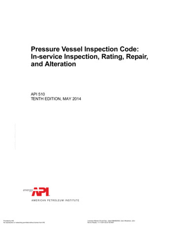
5.DETECTION & EVALUATION OF SPECIFIC DISCONTINUITIES:5.1CRACKS:None permitted.Crater cracks can propagate5.1.1 Heat Area Zone (HAZ) is defined as a surface condition on the basematerial adjacent to the toes of a weld that exhibits a mottled or texturedcondition with fine linear discontinuities.If shadows disappear under different lightingangles, the discontinuity is acceptableCrack in HeatAffected Zoneadjacent to weld toe5.2INCOMPLETE FUSION:Incompletefusion canbecomeexposed afterfinishing orgrindingoperationsNone permitted
5.3INCOMPLETE PENETRATION: When required by the welding symbol, fullpenetration groove welds welded from one side shall show complete joint penetration asevidenced by the absence of a joint line at the root of the weld. Full penetration groovewelds are required when the groove weld symbol appears by itself without additionalweld size or depth of bevel requirements or the depth of bevel equals material thicknessor if CJP appears in the tail of the welding symbol.
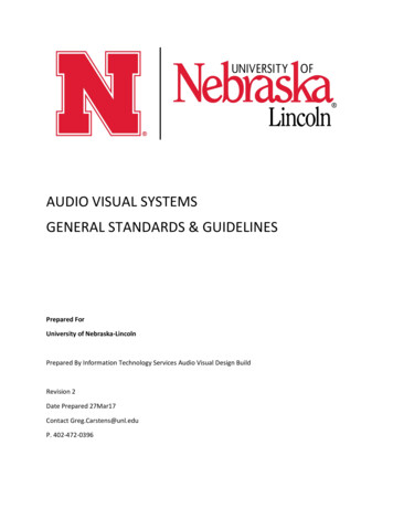
5.4MELT-THROUGH:5.4.1 For outside corner fillet welds without a melt-through symbol in thewelding symbol, complete joint penetration must be obtained as evidencedby any of the following; melting of the original edges, penetration of fillermetal into the root, a wavy uneven surface at the root, heat deformationwhen viewed from the back side of the weld.5.4.2 Where the welding symbol requires full penetration by evidence ofa melt-through symbol, complete joint must be obtained asevidenced by any of the following; melting of the original edges,penetration of filler metal into the root, a wavy uneven surface atthe root, heat deformation when viewed from the back side of theweld.Evidence of melt through mustbe seen in the jointNo evidence of melt through –original joint lines still visibleAcceptableRejectable5.5OVERLAP: Overlap shall be detected using the 90 oblique lighting technique.Hold the flashlight at approximately 90 to the toe of the weld being examined. Ifoverlap is present at the toe of the weld, a shadow will be cast under the overlap area.5.5.1All overlap shall be rejected.Use a strong light at 90 degrees atthe toe of the weld to detectoverlapShadows Reveal Overlap
5.5.2Convexity is acceptableLightingViewingConvexity is acceptable,overlap is not5.6ARC STRIKES: Arc strikes outside the area of deposited weld metal shall berejected. 5.7Can cause cracksNone permitted outside the weld zoneFILLET WELDS:5.7.1 When the size of the fillet weld is stated on the engineeringdrawing, the minimum fillet weld size shall be as shown in the weldingsymbol.5.7.2 When the fillet weld size is not stated on the print, the minimumfillet weld size shall be as stated below and shall be verified using theappropriate gage:
BASE MATERIALTHICKNESS (inches)0.010 to 0.0600.061 to 0.0900.091 to 0.01560.157 to 0.18750.188 to 0.2200.221 to 0.2500.251 to 0.31250.313 to 0.3750.376 to 0.43750.438 to 0.5000.501 to 0.6250.626 to 0.7500.752 to 0.8750.876 to 1.00MINIMUM FILLET WELD SIZE (1) WHEN NOT SPECIFIED ON THEDRAWING, IN INCHES (CUSTOM FILLET GAGE)SINGLE SIDE FILLET (2)DOUBLE SIDE FILLET 7500.5001.000.6251.2500.7501.310.8751.501.0(1) Weld size is determined by the thinner member.(2) Single side welds are welds made from only one side of the joint.(3) Double side welds are welds made on both sides of the joint.(4)Gages identified with fractional sizes may be used to inspect weldssized in decimal for instance; use a 1/8 fillet weld gage for a 0.12 weldcallout and use a 3/8 fillet weld gage for a 0.38 weld callout.5.7.3Fillet Weld Maximum Size - Where there is no print requirementfor maximum fillet weld size the following shall apply. Theminimum fillet weld size is established either by the print (takesprecedence) or from the table in para. 5.7.2, in either case theminimum fillet weld size shall be used to establish the maximumpermissible weld size from the table below and is applicable to allclasses.Fillet Weld Size – Maximum fillet weld size, based on minimum fillet weld sizefrom print or paragraph 5.7.2Fillet Weld Size (X)Fillet less than or equal to 0.063 in.greater than 0.063 but less than orequal to 0.157 in.greater than 0.157 but less than orequal to 0.250 in.Fillet greater than 0.250 in.Class AClass BClass C3X3X3X2½X2½X2½X2X2X2X1½X1½X1½X
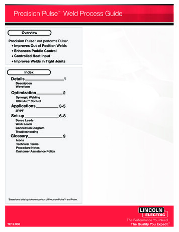
5.7.4Concave Fillet Weld5.7.5Convex Fillet Weld
5.8INTERMITTENT FILLET WELDS: When inspecting intermittent fillet welds, thefollowing sequence shall be used:Disregard weld start and stop areasthat are not full sized or completelyfused.5.8.1 Determine the effective length of each weld by discounting the portions of thestart and stop area at both ends of the weld that are not full size or that showevidence of roll over, a condition where the end of the weld is not tied into 1 orboth members.The welding symbol delineates the minimum effective weld lengthand the maximum pitch dimensionNOTE:The ends of intermittent fillet welds on aluminum may haveevidence of roll over. This is due to weld metal build-upresulting from a rosebud technique used to eliminate weldcraters. This portion of the weld will not be included in themeasurement to verify weld length and therefore is not arejectable indication.
5.95.8.2When roll over/incomplete fusion at the end of the fillets welds isobserved, the inspector shall use a 1/64” diameter pin gage tomeasure the length of roll over/incomplete fusion at the ends of theweld. This portion of the weld shall not be included whendetermining the effective length of the weld.5.8.2.1 The maximum length of incomplete fusion at the ends ofthe welds shall be .125”.5.8.3Set the dividers at the length dimension required for each weld.Verify that each of the individual welds have an effective length ofat least the dimension set on the dividers.5.8.4Mark the approximate center of each of the individual welds.5.8.5Set the dividers at the pitch dimension required by the weldingsymbol. Verify that the center-to-center distance between thecenter marks each of the intermittent welds does not exceed thedimension on the dividers.WELD BEAD WIDTH: The maximum weld bead width shall be as shown below:WELD PROCESSGMAW, GTAW, FCAW SAWSMAWMAXIMUM WIDTH.625” maximum2 ½ times the core diameter5.10 WELD REINFORCEMENT: (Excludes fillet welds) Weld reinforcement shallfair smoothly with itself and the base material. The maximum weld reinforcement shallbe as stated below for manual welds, machine welds refer to WS33739:MAXIMUM WELD REINFORCEMENTCLASSAB or CMATERIAL THICKNESS (T)MAXIMUM ALLOWABLEUp to .125" thick1TFor .126" to .510" thick1/3T or 0.100" whichever isgreater.510" and thicker0.170" maximumNo Stated RequirementNo Stated Requirement
5.11 DISCONTINUITIES: The discontinuities to be examined are only those listed inFigure 1. Two or more adjacent surface discontinuities shall be treated
This Visual Weld Inspection Guidelines can be used as a best practice for a supplier's approved weld inspectors. Prior to use the supplier shall review drawing requirements to assure welding requirements align to these guidelines. 2. POLICY: All weldments, including the weld and the adjacent base material, shall be visually inspected inch - by - inch in accordance with this guideline for .