Transcription
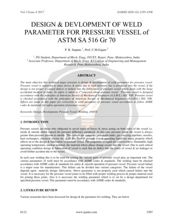
How to properly specify weld studs foruse with the drawn arc stud weldingprocess in structural applications.STUD WELDING DOES A PRETTY GREAT job ofkeeping things together—and quickly.The drawn arc stud welding process produces welds thatprovide a solid bond between a metal stud anchor and basemetal—commonly a steel plate embedded in concrete or thetop flange of a steel beam. It is a mechanized welding processthat produces a weld with full fusion between the stud base andthe base metal. Stud welds are stronger than the base metal orstud material alone, meaning that an engineer does not have tospecifically design the strength of the weld, and the drawn arcstud welding produces consistent quality repeated over manywelds. And, they can be installed in the down-hand, horizontaland overhead positions.But there’s plenty to consider when approaching a stud welding job, including specifying the correct stud type and the correct ceramic arc shield or ferrule for the intended stud application, determining the base diameter and the required after-weldlength (and corresponding before-weld length) of the stud, identifying the best material for the application and determining thestud’s purpose—i.e., how it is to be welded and/or applied.The Right Stud for the JobLet’s begin with weld stud types. Weld studs come in a variety of different configurations, sizes and lengths. In compositeconstruction the mechanical properties of embedded studs orstrength under tension and shear forces are typically governedby three things: the mechanical properties of the concrete, thegeometry of the concrete member around the studs and depthof embedment or stud length. Stud sizes range from very small(only a few millimeters in diameter and length) to very large(over 1 in. in diameter and 6 ft in length). Different types ofstuds may require specialized equipment and accessories—e.g.,welding very large studs in the down-hand position can strainthe limits of the welding equipment due to the physical weightof the stud.For carbon or mild steels, the American Welding Society(AWS) D1.1 Structural Welding Code—Steel, lists three types ofstuds based on use: Types A, B and C. Type A studs are generaluse studs for purposes other than shear transfer in compositeconstruction (and therefore will not be covered in this article).Type B weld studs with a formed head and Type C deformedbar anchor studs (DBAs) are the most common studs used incomposite construction. AWS D1.1 states: “Type B studs shallbe studs that are headed, bent or of other configuration in steelwiseSOLID BONDBY WILLIAM HOUSTON ANDIAN HOUSTON 8-in., ½-in., 5 8-in., ¾-in., 7 8-in. and 1-in. diameter that areused as an essential component in composite beam design andconcrete anchorage design.” And regarding Type C: “Type Cstuds shall be cold-worked deformed steel bars ”Headed weld studs are referred to as either concrete anchorsor shear connectors. In the AISC Specification for Steel Buildingsthey are referred to as steel headed stud anchors, while DBAsare headless studs that resemble steel reinforcing bars or rebar. They are designed with indented deformations, rather thanthe protruding deformations that are typically found on rebar,which allow the studs to be gripped by standard stud weldinggun accessories and welded with standard diameters of ceramicferrules. The welding process for headed anchors and DBAs isthe same and the latter are produced in many different shapesother than straight (e.g., hooked or bent) and usually requirespecialized welding accessories.The terms headed concrete anchor and shear connector areused to distinguish studs by size and primary use. A headedconcrete anchor is specified when the primary load is the samedirection as the shank of the stud (tensile), and the shank is typically smaller than that of a shear connector. As the name implies, shear connectors are used when the forces acting betweenthe steel and concrete are transverse (shearing) in direction.(We typically refer to a headed anchor with a 5 8-in.-diameteror smaller shank as a headed concrete anchor and studs with a¾-in. or greater diameter as shear connectors.)3William Houston (bill.houston@studwelding.com) is the generalmanager of Stud Welding Associates. Ian Houston (ian.houston@nelsonstud.com) is the construction engineering manager withNelson Stud Welding, Inc.Modern STEEL CONSTRUCTION
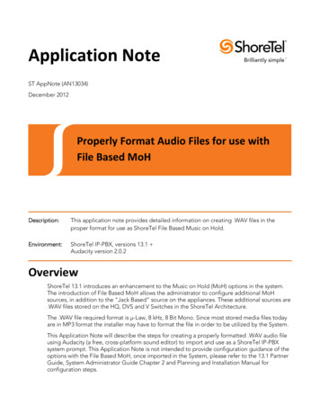
steelwise The drawn arc stud welding process produces welds that provide asolid bond between a metal stud anchor and base metal. Ceramic ferrules are needed to properly weld drawn arc weld studs. A sample weld stud. Weld studs can be installed in the down-hand, horizontal and overhead positions.JUNE 2015DiameterWhen choosing a stud diameter, prices increase alongwith diameters, though other factors should be consideredas well. First of all, the failure mechanics of a compositestructural assembly should be dictated by steel strength(ductile failure) rather than concrete strength (brittle failure). As stud diameter increases, the strength of the studalso increases. As the stud strength increases, the strengthof the concrete may also need to be increased to maintainthis ductile failure relationship of the composite structuralsystem. If a composite system is loaded beyond intendeddesign values, a large-diameter stud can be stronger thanthe surrounding concrete and the concrete can crusharound the stud, losing bond between the two materials.And as the studs lose bond, the composite system will losepart, if not all, of the combined steel and concrete strengththat the system relied on.A progressive failure like this can cause a brittle, potentially catastrophic failure of the entire structural system, such as a bridge collapse. Building codes that governcomposite construction and the transfer of forces between steel and concrete are written with the intent tomitigate these risks by guiding the design in such a waythat if a composite system does fail, it will be a ductilefailure and not a brittle failure. The ultimate failure of aductile connection, such as an embed plate with headedstuds, will be preceded by yielding of the stud materialrather than failure of the surrounding concrete by pullout, breakout or fracture.Defects are another factor to consider when choosingthe proper diameter. Welding defects, such as the phenomenon of arc blow, become greater and more frequentas stud diameter (increased weld times and current) increases. Stud diameter is also limited by the thickness ofthe plate or flange that the stud is being welded to. AISCSpecification I8.1 limits the stud diameter to 2.5 times thebase metal thickness while AWS D1.1 Clause limits studdiameters to 3 times the base metal thickness where thestud is welded directly to the base metal and 3 times thebase metal thickness where the stud is welded throughdeck; check the code governing your project. AWS D1.1considers the stud welding process to be prequalified,provided that the manufacturer has performed the properweld base qualification testing. AWS recognizes up to a1-in.-diameter stud. The largest diameter currently recognized by AISC for shear transfer of force from the concrete to a steel structure for welding through-deck applications, where the concrete is cast on steel form deckingsupported by a steel structure, is a ¾-in.-diameter stud;7 8-in.- and 1-in.-diameter studs are used in shear applications but are not commonly used in through-deck applications. We suggest consulting your stud manufacturerfor guidance in through-deck applications using diameters exceeding ¾ in.
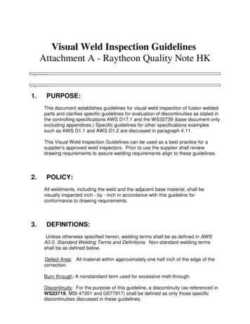
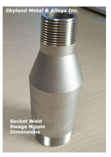
steelwise For carbon or mild steels, the American Welding Society(AWS) D1.1 Structural Welding Code—Steel, lists threetypes of studs based on use: Types A, B and C. Through-deck stud welding has specific stud size parameters.LengthDuring the stud welding process, a small amount of the studlength is melted, along with some of the base material, to create theweld pool. The amount of stud consumed is typically called burn-off,melt-off or burn-off/melt-off length. The melt-off length is proportional to the amount of arc current and total time of the weldingprocess. Since the values for current and time are proportional tothe stud diameter, it is simpler to relate melt-off length to diameter.When specifying studs, it is important to take into account thenominal melt-off length to determine the required stud length forthe application. Typically, studs are ordered by specifying the lengthbefore welding (the before-weld length). For example, if the specified stud length for the project is 6 in. and the stud diameter is ¾in., then the melt-off length is 3 16 in. The length specified on yourpurchase order should read: ¾ in. 63 16 in. headed shear connector(the 63 16-in. is the before-weld length).The following table lists the nominal melt-off lengths for a rangeof standard diameter studs when they are welded directly to steel intypical down-hand applications:Diameter Range (in.)Nominal Melt-Off Length (in.)3 8to ½1 85 8to 7 83 161 to 1¼¼AWS D1.1 allows studs to be fillet welded by traditional arcwelding techniques, such as SMAW, GMAW or TIG. If the stud iswelded by fillet welding, no melt-off will occur. If the studs are tobe welded through zinc-coated metal decking, melt-off lengths of 3 8inch and greater are possible. It is important to know how the studsare going to be welded and for what type of application. For thesereasons it is important to know how the studs are going to be weldedand the application involved (e.g., for a through-deck application, agood rule of thumb is a burn-off of ¼ in). JUNE 2015Various sizes of weld studs.Weld studs are produced in several materials, the mostcommon of which are carbon or mild steel, stainless steeland aluminum.MaterialWeld studs are produced in several materials, the most commonof which are carbon or mild steel, stainless steel and aluminum, andcertain applications, environments and loading conditions requirespecialized materials. For example, in a highly corrosive environment,such as steel embedded in concrete piers that are subjected to cyclesof wetting and drying from seawater, stainless steel studs should beused—and in cases where stainless studs are subjected to cyclic loading, annealing is required. It is also important to remember that mildsteel, stainless steel and aluminum studs are covered under differentAWS codes and therefore may have different requirements.Concerning the material properties of mild or carbon steel studs,AWS D1.1 states: “Studs shall be made from cold drawn bar conforming to the requirements of ASTM A29 Standard Specification forSteel Bars, Carbon and Alloy, Hot-Wrought, General Requirements forGrades 1010 through 1020.” AWS D1.1 Clause 7 Table 7.1 gives therequired mechanical properties for mild steel studs.Stainless steel studs are covered under the AWS D1.6 (StainlessSteel), which states: “Studs shall be made from cold drawn bar stock
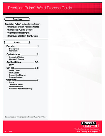
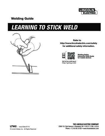
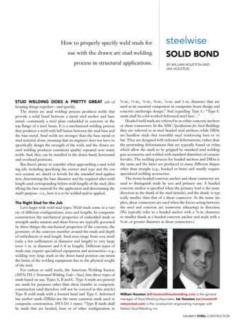
steelwiseAWS D1.1/2010 Structural Welding Code – Steel, Table 7.1Tensile StrengthYield Strength (0.2% Offset)Yield Strength (0.5% Offset)psi minMPa minpsi minMPa minReduction of AreaType B2Type –––70,000––48517%20%–min14%15%–³ Type C studs shall be cold-workeddeformed steel bar anchors.% min50%50%–MPa min% in 5x diameterconforming to ASTM A 493 Specification for Stainless Steel Wireand Wire Rods for Cold Heading and Cold Forging or ASTM A276Specification for Stainless Steel Bars and Shapes. The following300-series alloys may be used; XM-7, 304, 305, 309, 310 and316 or the low-carbon version thereof. Other Type 300 seriesmay be used with the approval of the engineer; however, Type303 shall not be used. Where studs are to be cyclically loaded,they shall be tested and furnished in the annealed condition.”Aluminum studs are covered under AWS D1.2 (Aluminum),but are not typically used in composite construction. And notethat properties for studs in the AWS D1.5 Bridge Welding Code varyfrom those in D1.1.Specifying the FerruleThe ceramic ferrule is needed to properly weld all drawn arcweld studs—the exception being very small-diameter studs andstuds with very fast weld times (referred to as short-cycle studs).The ferrule serves two purposes: It acts like a crucible to hold themolten metal around the base of the stud during the welding andcooling process, and it shields the molten metal from contamination by air, which can adversely affect the weld. Ferrules come inmany different shapes and sizes, each specifically designed for themany different stud welding applications possible.The most common ferrule, called a flat ferrule, is used whenthe stud is welded perpendicular to a flat horizontal surface belowthe stud (this is known as the down-hand position). Flat ferrulesare also used for overhead stud applications, such as hanger systems. For vertical applications (where welding studs are positionedhorizontally to a vertical surface) a special vertical ferrule withclosed vents along the bottom of the ferrule is used for studs thatare larger than ½ in. in diameter. Another common special ferruleapplication is for studs welded through metal decking materials toa supporting steel structure. This is called through-deck stud welding and requires a special “through-deck” ferrule; these ferruleshave larger vent openings to allow the zinc plating and other contaminates on the decking material to escape from the weld zone. IfMomenton headCrackingEnd ofbeam¹ Type A studs are for general purposeuse other than shear transfer in composite beam design and construction.² Type B studs are headed, bent, or ofother configurations used as an essentialcomponent in composite beamdesign and concrete anchorage design.psi min% in 2 in. minElongationType A1ForceCrushingForce distribution in concreteb) Shear connector fixed through profiled sheeting Modern STEEL CONSTRUCTION
steelwise It is important to take into account the nominal melt-off length todetermine the required stud le
AWS D1.1 Clause 7 Table 7.1 gives the required mechanical properties for mild steel studs. Stainless steel studs are covered under the AWS D1.6 (Stainless Steel), which states: “Studs shall be made from cold drawn bar stock steelwise Various sizes of weld studs. File Size: 225KBPage Count: 5