Transcription
Computers and Structures 72 (1999) 1 16Finite element analysis of uid ows fully coupled withstructural interactionsKlaus-JuÈrgen Bathe a,*, Hou Zhang b, Shanhong Ji baMassachusetts Institute of Technology, Mechanical Engineering Dept., Cambridge, MA 02139, USAbADINA R&D, Inc., 71 Elton Avenue, Watertown, MA 02472, USAAbstractSome advances in capabilities for analysis of uid ows fully coupled with structural interactions are presented.Incompressible Navier Stokes and compressible Navier Stokes or Euler uids and the full interaction withstructures undergoing large deformations, nonlinear material response and contact conditions can be considered.The analysis capabilities are available in the ADINA System, and are integrated within computer-aided design usingthe available ADINA modeler and CAD interfaces. Various analysis cases are presented to illustrate the solutioncapabilities. # 1999 Elsevier Science Ltd. All rights reserved.1. IntroductionThe solution of structural problems and uid owproblems is now well-established, although, of course,signi cant further advances in both elds are stillmuch needed. In structural analysis, advances for thesolution of highly nonlinear problems, such as encountered when considering mechanical coupling, are stillmuch desired, whereas in uid ow analysis signi cantimprovements in analysing high Reynolds and Pecletnumber ows are still sought. Of great importance inboth elds is also the establishment of precisely bounding and computable error measures for linear and nonlinear analysis [1].A relatively new eld of analysis is the solution offully coupled uid ows with structural interactions.Such analyses are the natural next step in modelingmany physical problems more accurately, for examplethose pertaining to motor car brake systems, disk* Corresponding author. Tel.: 1-617-253-6645; fax: 1617-253-2275.drives, compressors, the hydroplaning of tires, tallbuildings, bridges and airplanes in severe weather conditions, and biological systems such as arterial blood ows through stenoses.A simple but very restrictive approach to analysesuch systems is to perform the uid ow analysis rst,assuming the structure to be rigid, and then, given the uid forces acting onto the structure, perform thestructural analysis. If the structure does not deformsigni cantly and a steady-state analysis is su cient, thecomplete uid ow analysis is performed rst, andthen the structural analysis is carried out. In a transient analysis, the uid ow conditions usually changeduring the time integration (for example, when valvesopen or close) and such changes would need to be incorporated using frequent restarts in the analysis process. Of course, large deformations in the structurecannot be taken into account using this approach. Akey requirement is also that completely di erentmeshes (based on di erent elements) can be used forthe uid and the structure which renders the forcetransferÐas to be performed in this simpli ed analysis0045-7949/99/ - see front matter # 1999 Elsevier Science Ltd. All rights reserved.PII: S 0 0 4 5 - 7 9 4 9 ( 9 9 ) 0 0 0 4 2 - 5
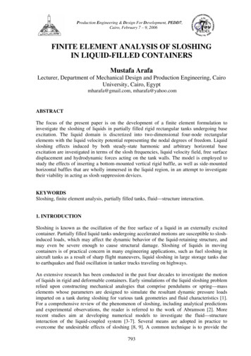
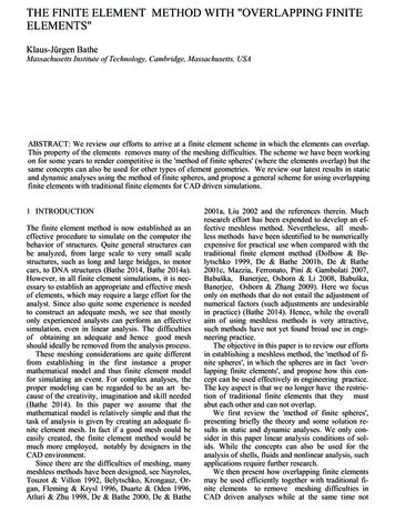
2K.J. Bathe et al. / Computers and Structures 72 (1999) 1 16approachÐfrom the uid domain to the structurecomplicated.The approach reported upon in this paper representsa very general procedure for the analysis of uid owswith structural interactions. The fully coupled steadystate or transient analysis is performed using theADINA program, for general linear or nonlinear structural conditions and incompressible or compressible uid ows. The structure can be subjected to nonlinearmaterial behavior and undergo very large displacements that have a drastic e ect on the uid ow andin turn on the structural conditions. The solution isobtained in a fully coupled manner at any timethroughout the complete time domain considered,using an arbitrary Lagrangian Eulerian formulationfor the uid and a Lagrangian formulation for thestructure.In the following sections of the paper, rst presentedare views of how, in practice, a fully coupled uid structure interaction (fsi) analysis might be performed.The paper then focuses on some capabilities availablein ADINA to model the structural and uid domains.This description includes a mentioning of some keyaspects of the nite element solution procedures,regarding the equations solved, the iterative solversand the mesh updating in the arbitrary Lagrangian Eulerian formulation. Then the results of some illustrative analyses that demonstrate the solution capabilitiesare presented, and nally in the last section of thepaper, conclusions are given regarding the currentstate of fsi analysis.requirement is that the geometry can be modi ed foranalysis purposes. The analysis requires in the rstinstance to construct an appropriate mathematicalmodel [1]. This model should contain all the importantingredients to answer the analysis questions with con dence, but should not involve undue complexity. Thepreparation of this model frequently involves changingthe given CAD geometry to remove details such asholes and chamfers that do not a ect the analysisanswers sought. Small geometric details require ne nite element meshes in these areas and if the detailsare not required, result in larger nite element systemsto be solved than is necessary.Considering ADINA, the CAD geometry would beread into ADINA-M (the ADINA System modeler) orbe constructed in this modeler. ADINA-M is using asits kernel Parasolid, and hence any geometry built in aParasolid-based CAD system can be directly loadedinto ADINA-M, see Fig. 1. The program also acceptsIGES les and Pro/E and AutoCAD geometry. Foranalysis purposes, the CAD geometry is then changed(that is, simpli ed) within ADINA-M. These changessurely depend on the complexity of the initial CAD2. fsi analysis in engineering practiceTo an increasing extent engineering analysis is beingperformed using computer-aided design tools todescribe the geometry. Typically, the geometry hasbeen generated using a CAD program such as Pro/E,SolidWorks, or I-DEAS, and the analysis is to be performed for the stresses, de ections, heat transfer, uid ow or pressure distributions in the envisaged design.The complete analysis may involve posing a number ofquestions in solid mechanics, uid mechanics and multiphysics. Traditionally, the solid and structural mechanics analyses are performed by a group of engineersusing certain analysis programs and the uid mechanics analyses are carried out by another group of analysts. Few analyses are conducted in which theinteractions between the structural components and uid ows are investigated, and then very simpli edmodels are used. However, the possibilities to performre ned structural, uid ow and interaction analyseshave dramatically increased in recent years.Assuming that the geometry of a design has beenconstructed with a CAD program, an importantFig. 1. Typical solution steps in an fsi problem.
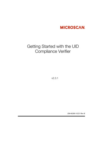
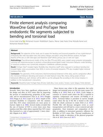
K.J. Bathe et al. / Computers and Structures 72 (1999) 1 16data, on whether a structural, uid ow or uid structure interaction analysis is to be conducted, and ofcourse on the actual mathematical model to be solved.In practice, the analyst best starts with the simplestpossible model and increases the complexity as needarises. ADINA can be used e ectively in this modelingprocess. For example, rst a simple to complex structural analysis may be conducted, then a uid owanalysis, a thermal analysis, and nally a uid owstructural interaction analysis corresponding to themultiphysics conditions may be pursued.To perform these analyses requires the constructionof the geometry, the generation of the nite elementmesh, the speci cation of the loading, boundary conditions and material data, the analysis solution usingthe solver program, and then the post-processing andvisualization of the analysis results, all performed inthe ADINA System.For the nite element meshing, the ADINA Systemo ers mapped and free-form meshing capabilities. Formapped meshing, all element types can be employed,but only simple geometries can be meshed. The free-3form meshing can be used for almost any geometry,but only triangular elements in two-dimensional andtetrahedral elements in three-dimensional conditionscan be employed. An important feature is that a complex geometry can be broken up into simpler geometricdomains and the di erent meshing tools can then beapplied to each of these domains. In this way, themapped meshing can be used in certain areas whilefree-form meshing is used in the rest of the geometry.The free-form meshing can be performed using anadvancing front procedure or a Delaunay scheme withsome control on minimizing sliver elements and formesh grading. For uid ow analysis, in particular,mesh grading in the boundary layers can be speci ed.An interface for the use of I-DEAS and Patran withthe ADINA System is also available. In this case, allgeometry construction, meshing and post-processing isperformed in I-DEAS or Patran, while the solution ofthe nite element model is carried out using ADINA.An example demonstrating the input preparation foran fsi analysis is shown in Fig. 2. In this case, theanalysis of a ow distributor is considered. The struc-Fig. 2. Analysis of ow distributor. (a) Geometry lines and surfaces. (b) Shaded image of geometry. (c) Shell nite element mesh.(d) Fluid nite element mesh.
4K.J. Bathe et al. / Computers and Structures 72 (1999) 1 16Fig. 2 (continued)ture is a exible thin shell and the device is used to distribute the ow of a quite viscous uid. The CAD program SolidWorks was used to construct the geometry,which was then loaded into ADINA-M. There was noneed to remove holes or other details. Using the freeform mesher for the complete system, the shell structure was meshed using the MITC 4-node shell element,and the uid domain was meshed using the tetrahedral3D uid ow element [1 3]. Fig. 2 shows these meshes,where it is seen that the structural mesh is considerablycoarser than the uid mesh; that is, a number of uidelements abut to a single shell element. This is, ofcourse, an important requirement for typical fsi analyses. The results of this analysis are given in Section4.1.3. ADINA capabilities for fsiConsider a generic domain partly uid and partlysolid, as schematically shown in Fig. 3. Note that thisdomain includes free surface(s) of the uid and ofcourse the uid structure interfaces. Our objective isto identify a mathematical model for the domain andsolve this model using nite element procedures.The solid is mathematically modeled using the classical Lagrangian formulations, whereas the uid is modeled using an arbitrary Lagrangian Eulerian (ALE)formulation of the Navier Stokes equations [1]. The uid can be a fully incompressible, a slightly compressible or a fully compressible medium. For the fullycompressible case, the Euler uid conditions (no vis-
K.J. Bathe et al. / Computers and Structures 72 (1999) 1 165Fig. 2 (continued)cous e ects) can also be assumed. The solid can be anactual two- or three-dimensional (2D or 3D) solid, ora beam, plate or shell structure.The equations governing the solid and uid responsehave been detailed in Refs. [1 3], where the mathematical model equations and the nite element discretizations used in ADINA have been summarized. Notethat the solid/structural domains can undergo verylarge motions with elastic or inelastic material conditions and can involve contact conditions [1,4]. The uid can contain free surfaces and is coupled to thestructure by satisfying the kinematic and equilibriumconditions between the uid and structural parts at the uid structure interfaces. The kinematic conditions arethe no-slip condition for the Navier Stokes uid andthe tangential slip condition when the special case ofan Euler uid is assumed.An important feature for the analysis of fsi problemsis the ALE formulation for the uid domain, in whichthe total time derivative for all the solution variables isgiven by [2,3],d d v ÿ vm r dtdt1 where d( )/dt is the transient term at the mesh positionconsidered. The mesh velocity at that position is givenby vm and the actual uid particle velocity is v. In thesolution vm is prescribed by the algorithm and must bechosen to achieve a stable and accurate solution. Theprimary purpose of using the ALE formulation is topreserve a good mesh quality when a change to the uid domain is imposed by a free surface or a uid structure interface. In ADINA, an algorithm can beemployed based on solving the Laplace equation fornodal positions in simple domains [2,3].Using ADINA, the solid/structure is meshed usingelement groups, and the uid is meshed independentlyin groups, but using of course the same pre-processor.
6K.J. Bathe et al. / Computers and Structures 72 (1999) 1 16Fig. 2 (continued)The uid structure interfaces are de ned on the geometry level by lines (in 2D analyses) and surfaces (in3D analyses).Assume that the nite element discretization hasbeen performed. The governing nite elementequations to be solved are then, for each discrete timet selected in the step-by-step solution,tF tR2 where2t3FFtF 4 t FI 5;t SF2t3RFtR 4 t RI 5t SR3 Here the vector tF lists the element nodal point forcescorresponding to the element internal stresses and theFig. 3. Schematic of fsi problem.
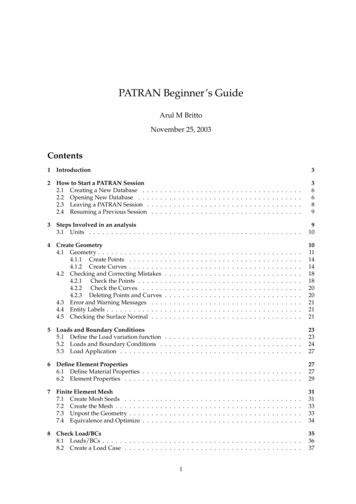
K.J. Bathe et al. / Computers and Structures 72 (1999) 1 167Fig. 4. Some solution results for analysis of ow distributor (for units see Table 1). (Top) E ective stress in shell. (Bottom)Velocity and pressure distributions at a section.vector tR lists the externally applied nodal point forcesincluding the inertia forces. In each vector, the forcescorresponding to the uid domains (superscript F), uid structure interfaces (superscript I) and solid/structural domains (superscript S) are listed. In Eq.(2), the interface equations involve the uid and solidelement meshes and describe the compatibility andforce transfer conditions along the interfaces for di er-ent element types and meshes in the solid and uiddomains.It should be noted that Eq.(2) contains all the ingredients and conditions for a fully coupled, steady-stateor transient analysis of the uid solid system. Thereare no additional conditions to be satis ed for a fullycoupled analysis of the system.In general, Eq. (2) is highly nonlinear in the uid
8K.J. Bathe et al. / Computers and Structures 72 (1999) 1 16Fig. 4 (continued)velocities and structural displacements. In addition, thenumber of equations can be very large. Of course, various solution strategies can be pursued. In structuralanalysis, Newton Raphson iteration is frequently moste ective, in which the resulting matrix equations aresolved using a sparse or an iterative solver [1]. In uid ow analysis, successive substitution and Gauss Seidel type iterative schemes are widely employed, butNewton Raphson iteration can also be e ective. Theconvergence in the iterations is frequently improved bynondimensionalizing the uid equations. An option isavailable in ADINA to have the program carry outthis nondimensionalization automatically based onuser-speci ed characteristic values of length, velocity,etc. Using the Newton Raphson method, the resultingmatrix equations are solved with an iterative schemesuch as the biconjugate gradient technique when thenumber of uid equations is very large. A sparse solveris, however, e ective if the number of equations con-sidered is not too large (say less than one-quartermillion equations).In ADINA, the user can select how to solve Eq. (2).For the nonlinearities, Newton Raphson iterations canbe used for the solid and the uid, and simple successive substitution can be employed for the uid. For theinterface conditions, successive substitution is usedwith an acceleration scheme. To solve the matrixequations of the uid and structural domains, sparsesolvers or iterative solvers with pre-conditioners (conjugate gradient and multigrid methods for the structure, and biconjugate gradient, GMRES and multigridmethods for the uid) can be used.4. ADINA sample solutionsThe objective in this section is to present some fsisolutions obtained with ADINA. These solutions illustrate the current capabilities available. Some additionalsolutions using ADINA have been given, for example,in Refs. [2,5 10].4.1. Analysis of ow distributorTable 1Material properties in ow distributor problemFluidStructurem 0.1413 lbm/ft sr 54.69 lbm/ft3E 2.0 106 lbf/ft2n 0.45The geometry and meshing of this ow device werealready presented in Section 2, see Fig. 2. Table 1 liststhe material properties used. In this analysis, the deformations of the structure are not very large, but the uid pressure exerts considerable forces on the structure. The coupled analysis gives the ow rates in the
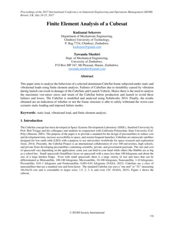
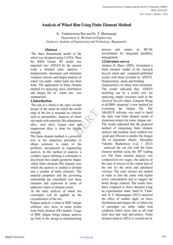
K.J. Bathe et al. / Computers and Structures 72 (1999) 1 169Fig. 5. Analysis of shock absorber. (a) Typical device. (b) Geometric entities. (c) Mesh of solid domain. (d) Mesh of uid domain.(e) Solution results, reaction force versus stroke.
Fig. 5 (continued)
K.J. Bathe et al. / Computers and Structures 72 (1999) 1 1611Fig. 5 (continued)various sections of the device, the pressure and viscousstresses in the uid and the stress distributions in thestructure, all in one analysis run.Some calculated quantities are shown in Fig. 4.4.2. Analysis of shock absorberA shock absorber, see Fig. 5, is subjected to aweight dropping on it. A laboratory experiment wasconducted to measure the reaction force as a functionof the stroke. ADINA was used to analyse the problem, with the aim to obtain detailed stress distributions in the structure. In the analysis, the uid wasassumed to be an almost incompressible Navier Stokes uid, and the structure was a solid with a part of itundergoing large displacements. Table 2 lists the material properties.For the analysis, ADINA-M was used to constructthe geometry, shown in Fig. 5(b). Note that the shockis absorbed by a piston pressing the uid out of theopening at the bottom of the structure. The nite el-ement meshes used are shown in Fig. 5(c) for the structure and Fig. 5(d) for the uid. These meshes are quitecoarse and yet, as seen in Fig. 5(e), the calculatedforce-stroke relationship is reasonably close to the experimental results. Only one single analysis of the problem was conducted without any tuning of the model.A key point is that the overall length of the shockabsorber is about 3.2 in, and the maximum stroke ofTable 2Material properties in shock absorber problemaFluidStructurem 0.8058 g/in sr 14.4008956 g/in3k 4 1010 g/in s2E 5.2578 1012 g/in s2n 0.3r 127.8186 g/in3aMass of the dropping weight 800 lb, initial velocity ofthe weight: 8 ft/s.
12K.J. Bathe et al. / Computers and Structures 72 (1999) 1 16Fig. 6. Analysis of air compressor (for units see Table 3). (a) Geometry of compressor and displacement of piston. (b) Mesh of uid. (c) Flow and pressure results at various times, t 1, 47, 65 and 99 (millisecs). (d) Valve opening as a function of time.the piston is about 2.5 in. Hence, the uid domain iscompressed by 2.5 in for an overall length of about 3.2in. This compression of the uid domain requires a mesh compression' of that magnitude, which is performed e ectively using the arbitrary Lagrangian Eulerian formulation used in ADINA.piston returns to its original position. The imposedmotion of the piston is given in Fig. 6(a).Fig. 6(b) shows the mesh used for the uid domainand Fig. 6(c) shows some calculated ow and pressureresults in the compressor. Fig. 6(d) shows the calculated opening of the valve. It is seen that the valve4.3. Analysis of air compressorThe air compressor shown in Fig. 6 was analysedfor the ow and structural response. In this analysis,the outer structure was assumed to be rigid, and onlythe valve was modeled as a exible structure. The uid(air) was assumed to be a fully compressible uid governed by the corresponding Navier Stokes equations.Table 3 lists the material properties used for the structure and the uid. The valve is initially closed, opensas the piston moves up, and then closes again as theTable 3Material properties in air compressor problemAirStructurecp 1004.5 m2/s2 Kcv 717.5 m2/s2 Km 1.5 10ÿ5 kg/m sr 1 kg/m3k 0.01 N/s KE 2 107 N/m2n 0.3r 3900 kg/m3
K.J. Bathe et al. / Computers and Structures 72 (1999) 1 1613Fig. 6 (continued)opening has some delay to reach the maximum opening, measured on the piston movement, and thatbecause of the time stepping used the valve closure isonly detected after, in fact, the valve has already overshot the closed-condition.5. Concluding remarksThe objective in this paper was to present someadvances in capabilities for the analysis of uid owswith structural interactions. The structural and uiddomains can be of a very general nature, that is, ofcomplex geometries, with the structure undergoinglarge deformations and the uid governed by theincompressibleorcompressibleNavier Stokesequations. An arbitrary Lagrangian Eulerian formulation is used to solve for the uid response with structural interface and free surface conditions.The key to successful solutions in engineering practice is that the capabilities can be employed in theCAD environment. This usage is achieved with someimportant solution ingredients: widely-employed CADpackages can be used to de ne the original geometry;the nite element system can be employed to modifythe geometry for analysis purposes and to de ne theanalysis parameters; the uid and structural domainscan be meshed automatically; and the arbitraryLagrangian Eulerian formulation is su ciently versatile to accommodate the possibly large motions of the uid boundaries.The ADINA System has been developed to o erthese capabilities, but of course further advances inthese areas will be pursued. The current state of theanalysis capabilities and the continuous furtheradvances should lead to many exciting applications inthe eld of uid ows with structural interactions.
K.J. Bathe et al. / Computers and Structures 72 (1999) 1 16Fig. 6 (continued)14
K.J. Bathe et al. / Computers and Structures 72 (1999) 1 16Fig. 6 (continued)15
16K.J. Bathe et al. / Computers and Structures 72 (1999) 1 16References[1] Bathe KJ. Finite element procedures. Prentice Hall, 1996.[2] Bathe KJ, Zhang H, Zhang X. Some advances in theanalysis of uid ows. Computers & Structures1997;64(5/6):909 30.[3] ADINA R&D Inc. ADINA Theory and ModelingGuides, Reports ARD 97-7 and 97-8.[4] Bathe KJ, Bouzinov PA. On the constraint functionmethod for contact problems. Computers & Structures1997;64(5/6):1069 85.[5] Bathe M, Kamm RD. A uid structure interaction niteelement analysis of pulsatile blood ow through a compliant stenotic artery, ASME, J Biomechanical Eng (inpress).[6] Wang X. Finite element analysis of air-sheet interactions[7][8][9][10]and utter suppression devices. Computers & Structures1997;64:983 94.Moore WI, Donovan ES, Powers CR. Thermal analysisof automotive lamps using the ADINA-F coupled specular radiation and natural convection model. Computers& Structures 1999;72(1 3):19 32.Wang X. Analytical and computational approaches forsome uid structure interaction analyses. Computers &Structures 1999;72(1 3):429 39.Tang D, Yang C, Huang Y. Wall stress and strain analysis using a 3-D thick-wall model with uid structure interactions for blood ow in carotid arteries withstenoses. Computers & Structures 1999;72(1 3):347 62.Tang D, Yang C. A 3-D thin-wall model with uid structure interactions for blood ow in carotid arterieswith symmetric and asymmetric stenoses. Computers &Structures 1999;72(1 3):363 83.
SolidWorks, or I-DEAS, and the analysis is to be per-formed for the stresses, deflections, heat transfer, fluid flow or pressure distributions in the envisaged design. The complete analysis may involve posing a number of questions in solid mechanics, fluid mechanics and mul-tiphysics. Traditionally, the solid and structural mech-