Transcription
International Journal of Engineering Research & Technology (IJERT)ISSN: 2278-0181Vol. 3 Issue 1, January - 2014Analysis of Wheel Rim Using Finite Element MethodK. Venkateswara Rao and Dr. T. DharmarajuDepartment of Mechanical EngineeringGodavari Institute of Engineering and Technology, RajamundryAbstractThe three dimensional model of thewheel was designed using CATIA. Thenthe IGES format 3D model wasimported into ANSYS. In the presentwork a detailed static analysis displacement, maximum and minimumvonmises stresses and fatigue analysis ofwheel rim under radial loads has beendone. The application of finite elementmethod for analyzing stress distributionand fatigue life of wheel rim wassummarized.1.Intorduction2.Literature surveyAndrew D. Hartz (2002) formulated afinite element model of the classicalbicycle wheel and compared publishedresults with those revealed by ANSYS.Displacement ,strain and bendingcharacteristics of wheel were etermined.The results indicated that ANSYSmodeling can be a useful tool foranalyzing simple structures such as theclassical bicycle wheel. Liangmo Wanget.al(2009) proposed a new method forevaluating the fatigue life, TheABAQUS software was used to buildthe static load finite element model ofaluminum wheels for rotary fatigue test.The results indicated that the proposedmethod of integrating finite elementanalysis and nominal stress method wasgood and efficient to predict the fatiguelife of aluminum wheels. AlexandruValentin Raduelescu et.al ( 2012)analyzed the car rim with the finiteelement method using the 40⁰ loadingtest The finite element analysis wasconducted in two stages- the analysis ofthe state of stresses in the central area ofthe rim for the intial and optimizedversions. The static stresses are studiedin order to find the zones with higherstress concentration and to suggest thebetter design solution. The results havebeen compared to those obtained usingan experimental stand. Sunil N. Yadavand N. S. Hanamapure (2013) analysedthe effect of camber angle on stressdistribution and fatigue life of wheel rimof passenger car under radial loadcondition which arises due to off roadfield area and road unevenness. Finiteelement analysis (FEA) is carried out byIJERTThe rim of a wheel is the outer circulardesign of the metal on which the insideedge of the tire is mounted on vehiclessuch as automobiles. Analysis of wheelrim made with materials like alluminiumalloy, steel alloy, forged steel andmagnesium alloy is done for fatiguestrength.The finite element method is a powerfultool or the numerical procedure toobtain solutions to many of theproblems encountered in engineeringanalysis. In this method of analysis, acomplex region defining a continuum isdiscretized into simple geometric shapescalled finite elements.The domain overwhich the analysis is studied is dividedinto a number of finite elements. Thematerial properties and the governingrelationship are considered over theseelements and expressed in terms ofunknown values at element corner.In the static analysis of wheel rimconstraints will be applied on thecircumference of the rim.Fatigue analysis is done in MSC fatiguesoftware, uses stress or strain resultsfrom finite element (FE) models. Usageof MSC fatigue brings fatigue analysisup front in the design-to-manufacturingprocess and creates an MCAEenvironment for integrated 59
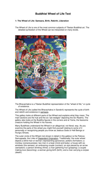
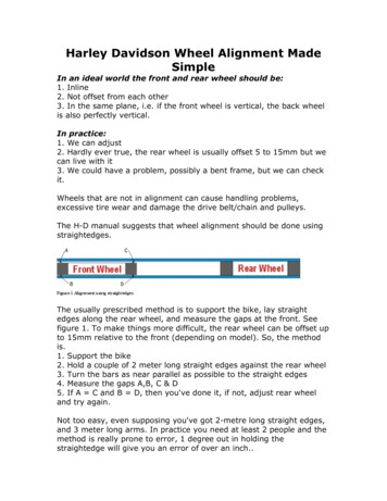
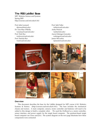
International Journal of Engineering Research & Technology (IJERT)ISSN: 2278-0181Vol. 3 Issue 1, January - 20143. Analysis of wheel rimAnalysis detailed static analysis -displacement,maximum and minimum vonmises stresses andfatigue analysis of wheel rim under radialloads,. We have consider the stell,aluminumalloy and magnesium,forged steel for analysisthe analysis following stepsMaterial propertiesModel of the whell rimImporting the modelBoundary conditions and LoadingApplication of load3.1 Material properties Forged steel:Young’s modulus (E) 210000N/mm2Yield stress 220 N/mm2Density 7600kg/m33.2 Model of wheel rimSOLID45 is used for the 3-D modeling of solidstructures. The element is defined by eight nodeshaving three degrees of freedom at each node:translations in the nodal x, y, and z directions.Table No.1 wheel rim dimensions450 mmHub hole diameter150 mmBolt hole diameter20 mmRim width254 mm3D Model of the wheel rimFig 1 Model of the wheel rim3.3 Importing the model The imported model is meshed by usingHyper mesh. the meshed model is asfollowsSteel alloy:Young’s modulus (E) 2.34*105 N/mm2Yield stress 240 N/mm2Density 7800kg/m3Aluminum alloy:Young’s modulus (E) 72000 N/mm2Yield stress 160 N/mm2Density 2800kg/m3Magnesium alloy:Young’s modulus (E) 45000N/mm2Yield stress 130 N/mm2Density 1800kg/m3IJERTV3IS10570Outer diameterIJERTsimulating the test conditions to analyzestress distribution and fatigue life of thesteel wheel rim of passenger carP.Meghashyam-et.al(2013) proposed thatthe modelling of the wheel rim is madebyusing CATIA. Later this CATIA model isimported to ANSYS for analysis work.ANSYS software is the latest used forsimulatingthe different forces, pressureacting on the component and also forcalculating and viewing the resultsANSYS static analysis work is carried outby considered two different materialsnamely aluminium and forged steel andtheir relative performances have beenobserved respectively. Inaddition to thisrim is subjected to vibration analysis(modal analysis), a part of dynamicanalysis is carried out its performanceisobserved. In this paper by observingthe results of both static and modalanalysis obtained forged steel issuggested as best materialFig 2: Meshing finished model The meshed model (.hm file format) ofwheel rim is imported from Hyper MeshSoftware to ANSYS Software.by(file Import IGES) Later this meshed model is defined withdifferent materials namely steel,Aluminum and Magnesium alloy andforged steel subjected to static analysiswww.ijert.org1260
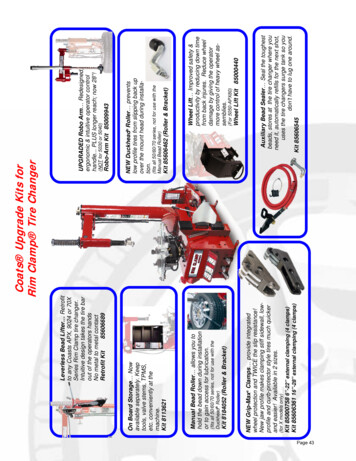
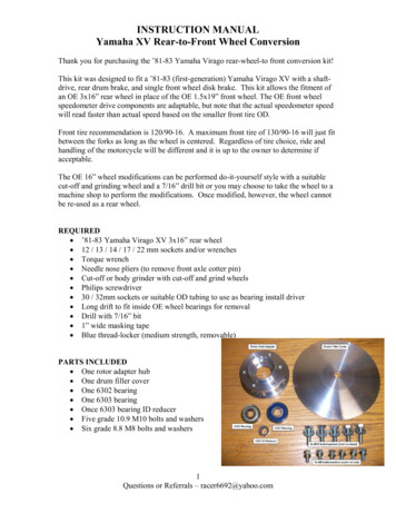
International Journal of Engineering Research & Technology (IJERT)ISSN: 2278-0181Vol. 3 Issue 1, January - 2014Aluminium alloyMagnesium alloyIJERTCentrifugal force, F mrω2 Nω 2*(22/7)*N/60 rad/sMass 24 kgSpeed 600 rpmω 62.8 rpsBy substituting, we get centrifugalforce 21.3kN which acts at each node of thecircumference of the rim.3.3 Boundary conditions and Loading:To get compressive and tensile stress, a load of21.3kN is applied on the bolt holes of the wheelrim. Displacementsa. Translation in x, y, z directions iszero.b. Rotation in x, y, z direction is zero. Angular velocity in x direction is zero,y direction is 62.8 rpsz direction is zero. These conditions are applied on the sixholes provided on the rim.In the same way, Centrifugal force is alsoapplied in the loading condition on the holes.3.4 Application of loadAfter this meshed model is constrained at holesby all DOF where the bolts has to be placed.After constraining the meshed model, the modelis subjected to a centrifugal force of 21.3kNLater the results were obtained in the SOLVERmodule.Then analysis type is changed fromstatic command to modal command and solutionis done. Next solution results such as stress,displacement, von mises, ultimate strength etc.were calucatedForged steel4.1.1 Displacement graph for alloy wheels4. RESULTS &DISCUSSION4.1 Displacement of Alloy wheelSteel alloyDisplacement graph for alloy wheelsIJERTV3IS10570www.ijert.org1261
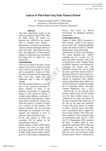
International Journal of Engineering Research & Technology (IJERT)ISSN: 2278-0181Vol. 3 Issue 1, January - 20144.2 Stress plots for alloy wheels4.3 Fatigue plots and S-N curvesSteel alloySteel alloyAluminium alloyIJERTAluminium alloyMagnesium alloyMagnesium alloyForged steelForged steel4.2.1 Stress Graph for Alloy wheelsSteel alloyIJERTV3IS10570www.ijert.org1262
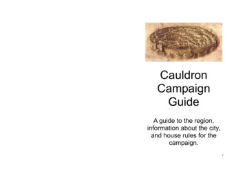
International Journal of Engineering Research & Technology (IJERT)ISSN: 2278-0181Vol. 3 Issue 1, January - 2014Fatigue graph for alloy wheelsMaterialAluminium alloyVonmisses stress(Mpa)Fatiguestrength(cycles)0.1663 140.0562.17*105Steelalloy48.3261.32*105Alumini 0.204um alloy1.2*105Magnesi 0.2136 32.29um alloy1.97*105Forged 0.1923 135.931steelOut of the different materials used steel alloywas found to have greater vonmisses stress of140.056Mpawhile magnesium alloy has the leastvonmisses stress of 32.29 Mpa. Steel alloy hasmaximum number of cycles tofailureNf) 2.17*105Cycle While magnesiumalloy has the least Number of cycles to failure(Nf) 1.2*105Cycles.IJERTMagnesium alloyDisplacement(mm)5.ConclusionForged Steel4.3.1 Fatigue graph for alloy wheelsIn steel alloy the number of cycles to failure isgreater than Aluminium alloy, Magnesium alloy andForged steel. Hence Steel alloy is more feasible to beused in wheel rim than other materials. Furtheroptimization of material thickness to reduce thematerial consumption can be done and we canimprove life of component by using advanced fatiguestrain life approach.6.References[ 1] Andrew D. Hartz “ Finite Element Analysis of theClassic Bicycle Wheel “ , Raytheon Engineering andProduction Support Indianapolis, Indiana ,July 18, 2002[2] Liangmo Wang* - Yufa Chen - Chenzhi Wang Qingzheng Wang et.al “ the fatigue analysis of aluminiumwheel rim” Strojniški vestnik - Journal of MechanicalEngineering 57(2011)1, 31-39-jme.2009.046[ 3] Alexandru Valentin Raduelescu –Sorin Cananau -IrinaRadulescu et.al “Mechanical testing methods concerningthe stress analysis for a vehicle wheel rim “olume2, 33-39[ 4] Sunil N. Yadav, et.al “Modeling and Analysis ofCamber Angle on Fatigue Life of Wheel Rim of PassengerCar by Using Radial Fatigue Testing “,InternationalJournal of Engineering Science and Innovative Technology(IJESIT) Volume 2, Issue 5, September 2013[ 5] P. Meghashyam- et.al “ Design andAnalysis ofWheel Rim using CATIA & ANSYS “ international journalof application or innovation in engineeringmanagement,Volume 2, Issue 8, August 2013IJERTV3IS10570www.ijert.org1263
life of aluminum wheels. Alexandru Valentin Raduelescu et.al ( 2012) analyzed the car rim with the finite ⁰loading test The finite element analysis was conducted in two stages- the analysis of the state of stresses in the